N8406-022A 1Gb Intelligent L2 Switch Application Guide Part number: 856-126757-106-00 First edition: July 2008
Legal notices © 2008 NEC Corporation. The information contained herein is subject to change without notice. The only warranties for NEC products and services are set forth in the express warranty statements accompanying such products and services. Nothing herein should be construed as constituting an additional warranty. NEC shall not be liable for technical or editorial errors or omissions contained herein. Microsoft®, Windows®, and Windows NT® are U.S. registered trademarks of Microsoft Corporation.
Contents Accessing the switch Introduction............................................................................................................................................................. 6 Additional references.............................................................................................................................................. 6 Typographical conventions.......................................................................................................................
Bridge Protocol Data Units ................................................................................................................................... 49 Determining the path for forwarding BPDUs ................................................................................................... 49 Spanning Tree Group configuration guidelines .................................................................................................... 50 Default Spanning Tree configuration.....................
Customer support tools ...................................................................................................................................
Accessing the switch Introduction This guide describes how to use and configure the switch on the Layer2 switch mode. For the information of how to use on the SmartPanel mode, see the SmartPanel Reference Guide. For the information of SSH, RADIUS, and TACACS+ on the SmartPanel mode, this guide will help you. This guide will help you plan, implement, and administer the switch software. Where possible, each section provides feature overviews, usage examples, and configuration instructions.
Management Network The 1Gb Intelligent L2 Switch is a Switch Module within the Blade Enclosure. The Blade Enclosure includes an Enclosure Manager Card which manages the modules and CPU Blades in the enclosure. The 1Gb Intelligent L2 Switch communicates with the Enclosure Manager Card through its internal management port (port 19). The factory default settings permit management and control access to the switch through the 10/100 Mbps Ethernet port on the Blade Enclosure, or the built-in console port.
Using the command line interfaces The command line interface (CLI) can be accessed via local terminal connection or a remote session using Telnet or SSH. The CLI is the most direct method for collecting switch information and performing switch configuration. The switch provides two CLI modes: The menu-based AOS CLI, and the tree-based ISCLI. You can set the switch to use either CLI mode.
4. 5. Configuring the default gateways allows the switch to send outbound traffic to the routers. >> IP Interface 256# ../gw 4 (Select default gateway 4) >> Default gateway 4# addr 205.21.17.1 (Assign IP address for a router) >> Default gateway 4# ena (Enable default gateway 4) Apply, verify, and save the configuration.
SNMP v3.0 SNMPv3 is an enhanced version of the Simple Network Management Protocol, approved by the Internet Engineering Steering Group in March, 2002. SNMP v3.0 contains additional security and authentication features that provide data origin authentication, data integrity checks, timeliness indicators, and encryption to protect against threats such as masquerade, modification of information, message stream modification, and disclosure.
View based configurations CLI user equivalent To configure an SNMP user equivalent to the CLI 'user,' use the following configuration: /c/sys/ssnmp/snmpv3/usm 4 name "usr" /c/sys/ssnmp/snmpv3/access 3 name "usrgrp" rview "usr" wview "usr" nview "usr" /c/sys/ssnmp/snmpv3/group 4 uname usr gname usrgrp /c/sys/ssnmp/snmpv3/view 6 name "usr" tree " 1.3.6.1.4.1.11.2.3.7.11.33.1.2.1.2" /c/sys/ssnmp/snmpv3/view 7 name "usr" tree " 1.3.6.1.4.1.11.2.3.7.11.33.1.2.1.3" /c/sys/ssnmp/snmpv3/view 8 name "usr" tree " 1.
Configuring SNMP trap hosts SNMPv1 trap host 1. Configure a user with no authentication and password. /c/sys/ssnmp/snmpv3/usm 10 name "v1trap" 2. Configure an access group and group table entries for the user. The command /c/sys/ssnmp/snmpv3/access /nview can be used to specify which traps can be received by the user. In the example below the user will receive the traps sent by the switch.
SNMPv2 trap host configuration The SNMPv2 trap host configuration is similar to the SNMPv1 trap host configuration. Wherever you specify the model you need to specify snmpv2 instead of snmpv1. c/sys/ssnmp/snmpv3/usm 10 name "v2trap" /c/sys/ssnmp/snmpv3/access 10 name "v2trap" model snmpv2 nview "iso" /c/sys/ssnmp/snmpv3/group 10 model snmpv2 uname v2trap gname v2trap /c/sys/ssnmp/snmpv3/taddr 10 name v2trap addr 47.81.25.
Secure access to the switch Secure switch management is needed for environments that perform significant management functions across the Internet. The following are some of the functions for secured management: • Limiting management users to a specific IP address range. See the “Setting allowable source IP address ranges” section in this chapter. • Authentication and authorization of remote administrators.
How RADIUS authentication works RADIUS authentication works as follows: 1. A remote administrator connects to the switch and provides the user name and password. 2. Using Authentication/Authorization protocol, the switch sends the request to the authentication server. 3. The authentication server checks the request against the user ID database. 4. Using RADIUS protocol, the authentication server instructs the switch to grant or deny administrative access.
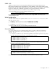
Configuring RADIUS on the switch (BBI example) 1. Configure RADIUS parameters. a. b. Click the Configure context button. Open the System folder, and select Radius. Open Select c. Enter the IP address of the primary and secondary RADIUS servers, and enter the RADIUS secret for each server. Enable the RADIUS server. CAUTION: If you configure the RADIUS secret using any method other than a direct console connection, the secret may be transmitted over the network as clear text. d. Click Submit.
2. Apply, verify, and save the configuration. 2. Verify 1. Apply 3. Save RADIUS authentication features The switch supports the following RADIUS authentication features: • Supports RADIUS client on the switch, based on the protocol definitions in RFC 2138 and RFC 2866. • Allows RADIUS secret password up to 32 bytes.
RADIUS attributes for user privileges When the user logs in, the switch authenticates the level of access by sending the RADIUS access request, that is, the client authentication request, to the RADIUS authentication server. If the authentication server successfully authenticates the remote user, the switch verifies the privileges of the remote user and authorizes the appropriate access.
Authorization Authorization is the action of determining a user’s privileges on the device, and usually takes place after authentication. The default mapping between TACACS+ authorization privilege levels and switch management access levels is shown in the table below. The privilege levels listed in the following table must be defined on the TACACS+ server.
Configuring TACACS+ authentication on the switch (AOS CLI example) 1. Turn TACACS+ authentication on, then configure the Primary and Secondary TACACS+ servers. >> Main# /cfg/sys/tacacs (Select the TACACS+ Server menu) >> TACACS+ Server# on (Turn TACACS+ on) Current status: OFF New status: ON >> TACACS+ Server# prisrv 10.10.1.1 (Enter primary server IP) Current primary TACACS+ server: 0.0.0.0 New pending primary TACACS+ server: 10.10.1.1 >> TACACS+ Server# secsrv 10.10.1.
Configuring TACACS+ authentication on the switch (BBI example) 1. Configure TACACS+ authentication for the switch. a. Click the Configure context button. b. Open the System folder, and select Tacacs+. Open Select c. Enter the IP address of the primary and secondary TACACS+ servers, and enter the TACACS+ secret. Enable TACACS+. d. Click Submit.
e. 2. Configure custom privilege-level mapping (optional). Click Submit to accept each mapping change. Apply, verify, and save the configuration. 2. Verify 1. Apply 3.
Secure Shell and Secure Copy Secure Shell (SSH) and Secure Copy (SCP) use secure tunnels to encrypt and secure messages between a remote administrator and the switch. Telnet does not provide this level of security. The Telnet method of managing a switch does not provide a secure connection. SSH is a protocol that enables remote administrators to log securely into the switch over a network to execute management commands. By default, SSH is disabled (off) on the switch.
Enabling or disabling SCP apply and save Enter the following commands from the switch CLI to enable the SCP putcfg_apply and putcfg_apply_save commands: >> # /cfg/sys/sshd/ena (Enable SCP apply and save) >> # /cfg/sys/sshd/dis (Disable SCP apply and save) SSHD# apply (Apply the changes) Configuring the SCP administrator password To configure the scpadmin (SCP administrator) password, first connect to the switch via the RS-232 management console.
For example: >> # scp ad4.cfg admin@205.178.15.157:putcfg Applying and saving configuration Enter the apply and save commands after the command above (scp ad4.cfg 205.178.15.157:putcfg), or use the following commands. You will be prompted for a password. >> # scp @:putcfg_apply >> # scp @:putcfg_apply_save For example: >> # scp ad4.cfg admin@205.178.15.157:putcfg_apply >> # scp ad4.cfg admin@205.178.15.
Generating RSA host and server keys for SSH access To support the SSH server feature, two sets of RSA keys (host and server keys) are required. The host key is 1024 bits and is used to identify the switch. The server key is 768 bits and is used to make it impossible to decipher a captured session by breaking into the switch at a later time. When the SSH server is first enabled and applied, the switch automatically generates the RSA host and server keys and is stored in the flash memory.
User access control The switch allows an administrator to define end user accounts that permit end users to perform limited actions on the switch. Once end user accounts are configured and enabled, the switch requires username/password authentication. For example, an administrator can assign a user who can log into the switch and perform operational commands (effective only until the next switch reboot). The administrator defines access levels for each switch user, as shown in the following table.
Ports and trunking Introduction The first part of this chapter describes the different types of ports used on the switch. This information is useful in understanding other applications described in this guide, from the context of the embedded switch/server environment. For specific information on how to configure ports for speed, auto-negotiation, and duplex modes, see the port commands in the Command Reference Guide.
Statistical load distribution In a configured trunk group containing more than one port, the load distribution is determined by information embedded within the data frame. For IP traffic, the switch will calculate the trunk port to use for forwarding traffic by implementing the load distribution algorithm on value equals to modulus of (XOR of last 3 bits of Source and last 3 bits of Destination IP address).
Port trunking example In this example, the Gigabit uplink ports on each switch, and the crosslink ports are configured into a total of five trunk groups: two on each switch, and one trunk group at the crosslink between the two switches. All ports operate at Gigabit Ethernet speed. NOTE: The actual mapping of switch ports to NIC interfaces is dependant on the operating system software, the type of server blade, and the enclosure type. For more information, see the User’s Guide.
Configuring trunk groups (AOS CLI example) 1. 2.
Configuring trunk groups (BBI example) 1. Configure trunk groups. a. Click the Configure context button on the Toolbar. b. Open the Layer 2 folder, and select Trunk Groups. Open Select c. Click a Trunk Group number to select it.
2. d. Enable the Trunk Group. To add ports, select each port in the Ports Available list, and click Add. e. Click Submit. Apply, verify, and save the configuration. 2. Verify 1. Apply 3. Save 3. Examine the trunking information on each switch. a. Click the Dashboard context button on the Toolbar.
b. Select Trunk Groups. Open Select c. Information about each configured trunk group is displayed. Make sure that trunk groups consist of the expected ports and that each port is in the expected state. Configurable Trunk Hash algorithm This feature allows you to configure the particular parameters for the switch Trunk Hash algorithm instead of having to utilize the defaults. You can configure new default behavior for Layer 2 traffic and Layer 3 traffic, using the CLI menu cfg/l2/thash.
Link Aggregation Control Protocol Link Aggregation Control Protocol (LACP) is an IEEE 802.3ad standard for grouping several physical ports into one logical port (known as a dynamic trunk group or Link Aggregation group) with any device that supports the standard. Refer to the IEEE 802.3ad-2002 for a full description of the standard. The 802.3ad standard allows standard Ethernet links to form a single Layer 2 link using the Link Aggregation Control Protocol (LACP).
Configuring LACP Use the following procedure to configure LACP for port 20 and port 21 to participate in link aggregation. 4. Set the LACP mode on port 20. >> # /cfg/l2/lacp/port 20 >> LACP port 20# mode active 5. Define the admin key on port 20. Only ports with the same admin key can form a LACP trunk group. >> LACP port 20# adminkey 100 Current LACP port adminkey: 20 New pending LACP port adminkey: 100 6. (Set port 21 adminkey to 100) Apply and verify the configuration.
VLANs Introduction This chapter describes network design and topology considerations for using Virtual Local Area Networks (VLANs). VLANs are commonly used to split up groups of network users into manageable broadcast domains, to create logical segmentation of workgroups, and to enforce security policies among logical segments.
Viewing and configuring PVIDs You can view PVIDs from the following AOS CLI commands: Port information >> /info/port Port Tag RMON PVID NAME VLAN(s) ---- --- ---- ---- -------------- ------------------------------1 n d 1 Downlink1 1 2 n e 1 Downlink2 1 3 n d 1 Downlink3 1 4 n d 1 Downlink4 1 5 n d 1 Downlink5 1 6 n d 1 Downlink6 1 7 n d 1 Downlink7 1 : : Port configuration >> /cfg/port 22/pvid 22 Current port VLAN ID: 1 New pending port VLAN ID: 22 >> Port 22# Each port on the switch can belong to one or
Figure 2 Default VLAN settings NOTE: The port numbers specified in these illustrations may not directly correspond to the physical port configuration of your switch model. When you configure VLANs, you configure the switch ports as tagged or untagged members of specific VLANs. See the following figures. In the following figure, the untagged incoming packet is assigned directly to VLAN 2 (PVID = 2). Port 5 is configured as a tagged member of VLAN 2, and port 7 is configured as an untagged member of VLAN 2.
Figure 4 802.1Q tagging (after port-based VLAN assignment) In the following figure, the tagged incoming packet is assigned directly to VLAN 2 because of the tag assignment in the packet. Port 5 is configured as a tagged member of VLAN 2, and port 7 is configured as an untagged member of VLAN 2. Figure 5 802.1Q tag assignment As shown in the following figure, the tagged packet remains unchanged as it leaves the switch through port 5, which is configured as a tagged member of VLAN 2.
VLANs and IP interfaces Carefully consider how you create VLANs within the switch, so that communication with the switch remains possible. In order to access the switch for remote configuration, trap messages, and other management functions, be sure that at least one IP interface on the switch has a VLAN defined. You can also inadvertently cut off access to management functions if you exclude the ports from the VLAN membership.
Multiple VLANS with tagging The following figure shows only those switch port to server links that must be configured for the example. While not shown, all other server links remain set at their default settings. Figure 7 Multiple VLANs with VLAN tagging The features of this VLAN are described in the following table: NOTE: The port numbers specified in these illustrations may not directly correspond to the physical port configuration of your switch model.
Table 9 Multiple VLANs with tagging Component Description CPU Blade Server #2 This blade server belongs to VLAN 3. The port that the VLAN is attached to is configured only for VLAN 3, so VLAN tagging is off. This PC is a member of VLAN 2 and 3. Via VLAN 2, it can communicate with Server 1, PC 3, and PC 5. Via VLAN 3, it can communicate with Server 1, Server 2, and PC 4. This PC is a member of VLAN 4, and can only communicate with Server 1. This PC is a member of VLAN 1 and VLAN 2.
2. Configure the VLANs and their member ports. Since all ports are by default configured for VLAN 1, configure only those ports that belong to VLAN 2. crosslink ports 17 and 18 must belong to VLANs 1 and 3.
2. Configure the VLANs and their member ports. Since all ports are by default configured for VLAN 1, configure only those ports that belong to other VLANs.
c. Click a port number to select it. d. Enable the port and enable VLAN tagging. e. Click Submit.
2. Configure the VLANs and their member ports. a. Open the Virtual LANs folder, and select Add VLAN. Open Select b. Enter the VLAN name, VLAN ID number, and enable the VLAN. To add ports, select each port in the Ports Available list and click Add. Since all ports are configured for VLAN 1 by default, configure only those ports that belong to VLAN 2. The crosslink ports 17 and 18 must belong to VLANs 1 and 2. c. Click Submit.
The external Layer 2 switches should also be configured for VLANs and tagging. 3. Apply, verify, and save the configuration. 2. Verify 1. Apply 3. Save FDB static entries Static entries in the Forwarding Database (FDB) allow the switch to forward packets without flooding ports to perform a lookup. A FDB static entry is a MAC address associated with a specific port and VLAN. The switch supports 128 static entries. Static entries are manually configured, using the /cfg/l2/fdb/static command.
Spanning Tree Protocol Introduction When multiple paths exist on a network, Spanning Tree Protocol (STP) configures the network so that a switch uses only the most efficient path. The following topics are discussed in this chapter: • Overview • Bridge Protocol Data Units (BPDUs) • Spanning Tree Group (STG) configuration guidelines • Multiple Spanning Trees Overview Spanning Tree Protocol (STP) detects and eliminates logical loops in a bridged or switched network.
Port path cost The port path cost assigns lower values to high-bandwidth ports, such as Gigabit Ethernet, to encourage their use. The objective is to use the fastest links so that the route with the lowest cost is chosen. A value of 0 indicates that port cost is computed dynamically based on link speed. This works when forcing link speed, so it does not just apply to “auto negotiated link speed”. By default, all switch ports have the path cost set to 4, independent of the link speed.
Adding and removing ports from STGs Information on adding and removing ports from STGs is as follows: • By default, all ports except Port 19 belong to VLAN 1 and STG 1. • Each port is always a member of at least one VLAN. Each VLAN is always a member of at least one STG. Port membership within VLANs can be changed, and VLAN membership within STGs can be changed. To move a port from one STG to another, move the VLAN to which the port belongs, or move the port to a VLAN that belongs to the STG.
Figure 8 Two VLANs on one instance of Spanning Tree Protocol In the following figure, VLAN 1 and VLAN 2 belong to different Spanning Tree Groups. The two instances of spanning tree separate the topology without forming a loop, so that both VLANs can forward packets between the switches without losing connectivity.
Configuring Switch 1 (AOS CLI example) 1. Configure port and VLAN membership on Switch 1 as described in the “Configuring ports and VLANs on Switch 1 (AOS CLI example)” section, in the “VLANs” chapter of this guide. 2. Add VLAN 2 to Spanning Tree Group 2. >> /cfg/l2/stp 2 >> Spanning Tree Group 2# add 2 (Select Spanning Tree Group 2) (Add VLAN 2) VLAN 2 is automatically removed from spanning tree group 1. 3. Apply and save.
3. c. Enter the Spanning Tree Group number and set the Switch Spanning Tree State to on. To add a VLAN to the Spanning Tree Group, select the VLAN in the VLANs Available list, and click Add. VLAN 2 is automatically removed from Spanning Tree Group 1. d. Scroll down, and click Submit. Apply, verify, and save the configuration. 2. Verify 1. Apply 3.
Configuring Port Fast Forwarding Use the following CLI commands to enable Port Fast Forwarding on an external port.
RSTP and MSTP Introduction Rapid Spanning Tree Protocol (IEEE 802.1w) enhances the Spanning Tree Protocol (IEEE 802.1D) to provide rapid convergence on Spanning Tree Group 1. Multiple Spanning Tree Protocol (IEEE 802.1s) extends the Rapid Spanning Tree Protocol to provide both rapid convergence and load balancing in a VLAN environment.
RSTP configuration guidelines This section provides important information about configuring Rapid Spanning Tree Groups: • When RSTP is turned on, STP parameters apply only to STP Group 1. • When RSTP is turned on, all VLANs from STP Groups other than STP Group 1 are moved to STP Group 1. The other STP Groups (2-32) are turned off.
b. Open the MSTP/RSTP folder, and select General. Open Select 3. c. Select RSTP mode, and set the MSTP/RSTP state to ON. d. Click Submit. Apply, verify, and save the configuration. 2. Verify 1. Apply 3.
Multiple Spanning Tree Protocol IEEE 802.1s Multiple Spanning Tree extends the IEEE 802.1w Rapid Spanning Tree Protocol through multiple Spanning Tree Groups. MSTP maintains up to 32 spanning-tree instances that correspond to STP Groups 1-32. In Multiple Spanning Tree Protocol (MSTP), several VLANs can be mapped to each Spanning-Tree instance. Each Spanning-Tree instance is independent of other instances.
3. Assign VLANs to Spanning Tree Groups. >> /cfg/l2/stp 2 (Select Spanning Tree Group 2) >> Spanning Tree Group 2# add 2 (Add VLAN 2) >> Spanning Tree Group 2# apply (Apply the configurations) Configuring Multiple Spanning Tree Protocol (BBI example) 1. Configure port and VLAN membership on the switch, as described in the “Configuring ports and VLANs (BBI example)” section in the “VLANs” chapter of this guide. 2. Configure MSTP general parameters. a.
3. Configure Common Internal Spanning Trees (CIST) bridge parameters. a. Open the MSTP/RSTP folder, and select CIST-Bridge. Open Select b. Enter the Bridge Priority, Maximum Age, and Forward Delay values. c. Click Submit.
4. Configure Common Internal Spanning Tree (CIST) port parameters. a. Open the MSTP/RSTP folder, and select CIST-Ports. Open Select b. Click a port number to select it.
5. c. Enter the Port Priority, Path Cost, and select the Link Type. Set the CIST Port State to ON. d. Click Submit. Apply, verify, and save the configuration. 2. Verify 1. Apply 3.
IGMP Snooping Introduction IGMP Snooping allows the switch to forward multicast traffic only to those ports that request it. IGMP Snooping prevents multicast traffic from being flooded to all data ports. The switch learns which server hosts are interested in receiving multicast traffic, and forwards it only to ports connected to those servers.
IGMP Filtering With IGMP Filtering, you can allow or deny a port to send and receive multicast traffic to certain multicast groups. Unauthorized users are restricted from streaming multicast traffic across the network. If access to a multicast group is denied, IGMP Membership Reports from the port for that group are dropped, and the port is not allowed to receive IP multicast traffic from that group.
3. View dynamic IGMP information. >> /info/l3/igmp (Select IGMP Information menu) >> IGMP Multicast# dump (Show IGMP Group information) >> Switch-A - IGMP Multicast# dump Group ----------238.1.0.0 238.1.0.
3. Assign the IGMP Filter to a port. >> //cfg/l3/igmp/igmpflt (Select IGMP Filtering menu) >>IGMP Filter# port 24 (Select port 24) >>IGMP Port 24# filt ena (Enable IGMP Filtering on the port) Current port 24 filtering: disabled New port 24 filtering: enabled >>IGMP Port 24# add 1 (Add IGMP Filter 1 to the port) >>IGMP Port 24# apply (Make your changes active Configuring a Static Mrouter (CLI example) 1. Configure a port to which the static Mrouter is connected, and enter the appropriate VLAN.
3. c. Enable IGMP Snooping. d. Click Submit. Apply, verify, and save the configuration. 2. Verify 1. Apply 3.
Configuring IGMP Filtering (BBI example) 1. Configure IGMP Snooping. 2. Enable IGMP Filtering. a. Click the Configure context button. b. Open the IGMP folder, and select IGMP Filters (click the underlined text, not the folder). Open Select c. Enable IGMP Filtering globally. d. Click Submit.
3. Define the IGMP Filter. a. Select Layer 3 > IGMP > IGMP Filters > Add Filter. Open Select b. Enable the IGMP Filter. Assign the range of IP multicast addresses and the filter action (allow or deny). c. Click Submit.
4. Assign the filter to a port and enable IGMP Filtering on the port. a. Select Layer 3 > IGMP > IGMP Filters > Switch Ports. Open Select b. Select a port from the list.
5. c. Enable IGMP Filtering on the port. Select a filter in the IGMP Filters Available list, and click Add. d. Click Submit. Apply, verify, and save the configuration. 2. Verify 1. Apply 3.
Configuring a Static Multicast Router (BBI example) 1. Configure Static Mrouter. a. 2. Click the Configure context button. b. Open the Switch folder and select IP Menu > IGMP > IGMP Static MRouter. c. Enter a port number, VLAN ID number, and IGMP version number. d. Click Submit. Apply, verify, and save the configuration. 2. Verify 1. Apply 3.
Remote monitoring Introduction Remote Monitoring (RMON) allows network devices to exchange network monitoring data. RMON performs the following major functions: • Gathers cumulative statistics for Ethernet interfaces • Tracks a history of statistics for Ethernet interfaces • Creates and triggers alarms for user-defined events Overview The RMON MIB provides an interface between the RMON agent on the switch and an RMON management application. The RMON MIB is described in RFC 1757.
2. View RMON statistics for the port.
2. Select a port. 3. Enable RMON on the port.
4. Click Submit. 5. Apply, verify, and save the configuration. 2. Verify 1. Apply 3. Save RMON group 2 — history The RMON History group allows you to sample and archive Ethernet statistics for a specific interface during a specific time interval. The switch supports up to five RMON History groups. NOTE: RMON port statistics must be enabled for the port before an RMON history group can monitor the port. Data is stored in buckets, which store data gathered during discreet sampling intervals.
Configure RMON History (BBI example) 1. Configure an RMON History group. a. Click the Configure context button. b. Open the Switch folder, and select RMON > History > Add History Group. Open Select 2. Configure RMON History Group parameters. 3. Click Submit. 4. Apply, verify, and save the configuration. 2. Verify 1. Apply 3.
RMON group 3 — alarms The RMON Alarm group allows you to define a set of thresholds used to determine network performance. When a configured threshold is crossed, an alarm is generated. For example, you can configure the switch to issue an alarm if more than 1,000 CRC errors occur during a 10-minute time interval. The switch supports up to 30 RMON Alarm groups. Each Alarm index consists of a variable to monitor, a sampling time interval, and parameters for rising and falling thresholds.
Configure RMON Alarms (AOS CLI example 2) 1. Configure the RMON Alarm parameters to track ICMP messages. >> /cfg/rmon/alarm 5 (Select RMON Alarm 5) >> RMON Alarm 5# oid 1.3.6.1.2.1.5.8.0 >> RMON Alarm 5# intrval 60 >> RMON Alarm 5# almtype rising >> RMON Alarm 5# rlimit 200 >> RMON Alarm 5# revtidx 5 >> RMON Alarm 5# sample delta >> RMON Alarm 5# owner “Alarm_for_icmpInEchos” 2. Apply and save the configuration.
Configure RMON Alarm Group parameters to check ifInOctets on port 19 once every hour. Enter a rising limit of two billion, and a rising event index of 6. This configuration creates an RMON alarm that checks ifInOctets on port 19 once every hour. If the statistic exceeds two billion, an alarm is generated that triggers event index 6. 2. Click Submit. 3. Apply, verify, and save the configuration. 2. Verify 1. Apply 3.
Configure RMON Alarms (BBI example 2) 1. Configure an RMON Alarm group. a. Click the Configure context button. b. Open the Switch folder, and select RMON > Alarm > Add Alarm Group. Open Select Configure RMON Alarm Group parameters to check icmpInEchos, with a polling interval of 60, a rising limit of 200, and a rising event index of 5. This configuration creates an RMON alarm that checks icmpInEchos on the switch once every minute.
3. Apply, verify, and save the configuration. 2. Verify 1. Apply 3. Save RMON group 9 — events The RMON Event group allows you to define events that are triggered by alarms. An event can be a log message, an SNMP trap message, or both. The switch supports up to 30 RMON Event groups. When an alarm is generated, it triggers a corresponding event notification. Use the /cfg/rmon/alarm x/revtidx and /fevtidx commands to correlate an event index to an alarm.
Configuring RMON Events (BBI example) 1. Configure an RMON Event group. a. b. Click the Configure context button. Open the Switch folder, and select RMON > Event > Add Event Group. Open Select Configure RMON Event Group parameters. This configuration creates an RMON event that sends a SYSLOG message each time it is triggered by an alarm. 2. Click Submit. 3. Apply, verify, and save the configuration. 2. Verify 1. Apply 3.
High availability Introduction Switches support high availability network topologies. This release provides information about Uplink Failure Detection. Uplink Failure Detection Uplink Failure Detection (UFD) is designed to support Network Adapter Teaming on the CPU Blades. UFD allows the switch to monitor specific uplink ports to detect link failures. When the switch detects a link failure, it automatically disables specific downlink ports.
Failure Detection Pair To use UFD, you must configure a Failure Detection Pair and then turn UFD on. A Failure Detection Pair consists of the following groups of ports: • Link to Monitor (LtM) The Link to Monitor group consists of one uplink port (20-24), one trunk group that contains only uplink ports, or one LACP trunk group that contains only uplink ports. The switch monitors the LtM for link failure.
Monitoring Uplink Failure Detection The UFD information menu displays the current status of the LtM and LtD, and their member ports or trunks. For example: >> Information# ufd Uplink Failure Detection 1: Enabled LtM status: Down Member STG STG State Link Status -------------------------------port 24 down 1 DISABLED 10 DISABLED * 15 DISABLED * * = STP turned off for this port.
Configuring UFD on Switch 2 (AOS CLI example) 1. 2. Create a trunk group of uplink ports (20-24) to monitor. First you must set each port to full duplex mode.
2. d. Enable the FDP. Select ports in the LtM Ports Available list, and click Add to place the ports into the Link to Monitor (LtM). Select ports in the LtD Ports Available list, and click Add to place the ports into the Link to Disable (LtD). e. Click Submit. Apply, verify, and save the configuration. 2. Verify 1. Apply 3.
Troubleshooting tools Introduction This appendix discusses some tools to help you use the Port Mirroring feature to troubleshoot common network problems on the switch. Port Mirroring The Port Mirroring feature on the switch is very useful for troubleshooting any connection-oriented problem. Any traffic in or out of one or more ports can be mirrored to a single monitoring port to which a network monitor can be attached.
Configuring Port Mirroring (AOS CLI example) To configure Port Mirroring for the example shown in the preceding figure: 1. Specify the monitoring port. >> # /cfg/pmirr/monport 20 2. (Select port 20 for monitoring) Select the ports that you want to mirror.
Configuring Port Mirroring (BBI example) 1. Configure Port Mirroring. a. Click the Configure context button. b. Open the Switch folder, and select Port-Based Port Mirroring (click the underlined text, not the folder). Open Select c. Click a port number to select a monitoring port. d. Click Add Mirrored Port.
2. e. Enter a port number for the mirrored port, and select the Port Mirror Direction. f. Click Submit. Apply, verify, and save the configuration. 2. Verify 1. Apply 3. Save 3. Verify the Port Mirroring information on the switch.
Other network troubleshooting techniques Other network troubleshooting techniques include the following. Console and Syslog messages When a switch experiences a problem, review the console and Syslog messages. The switch displays these informative messages when state changes and system problems occur. Syslog messages can be viewed by using the /info/sys/log command. For more information on interpreting syslog messages, see the Command Reference Guide.