TM LCD4000
Table of Contents Important Information .......................................................................................................................... 1 Safety Precautions, Maintenance, & Recommended Use ................................................................. 2 Contents .................................................................................................................................................... 3 Attaching LCD Options ..............................................
Important Information WARNING TO PREVENT FIRE OR SHOCK HAZARDS, DO NOT EXPOSE THIS UNIT TO RAIN OR MOISTURE. ALSO, DO NOT USE THIS UNIT'S POLARIZED PLUG WITH AN EXTENSION CORD RECEPTACLE OR OTHER OUTLETS UNLESS THE PRONGS CAN BE FULLY INSERTED. REFRAIN FROM OPENING THE CABINET AS THERE ARE HIGH VOLTAGE COMPONENTS INSIDE. REFER SERVICING TO QUALIFIED SERVICE PERSONNEL. CAUTION CAUTION:TO REDUCE THE RISK OF ELECTRIC SHOCK, MAKE SURE POWER CORD IS UNPLUGGED FROM WALL SOCKET.
Safety Precautions, Maintenance & Recommended Use Safety Precautions and Maintenance Recommended Use CAUTION FOR OPTIMUM PERFORMANCE, PLEASE NOTE THE FOLLOWING WHEN SETTING UP AND USING THE LCD4000 LCD COLOR MONITOR: • DO NOT OPEN THE MONITOR. There are no user serviceable parts inside and opening or removing covers may expose you to dangerous shock hazards or other risks. Refer all servicing to qualified service personnel. • Do not spill any liquids into the cabinet or use your monitor near water.
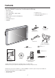
Contents Your new LCD4000™ monitor box* should contain the following: • • • • • • • • LCD monitor Power Cord (3m) Video Signal Cable – SC-B113 (4m) User’s Manual Wireless Remote Control and AA Batteries Clamper x 2 Screw (M4 x 10) x 2 CD-ROM • Ferrite Core x 2 • Stand for the Independence x 2 • Screw (M5 x 40) x 4 Stand for the Independence x 2 Screw (M5 x 40) for stand x 4 Power Cord Video Signal Cable (D-SUB to D-SUB Cable) Clamper x 2 Screw (M4 x 10 ) x 2 Ferrite Core x 2 TM LCD4000 User’s Manua
Attaching LCD Options Ventilation Requirements for enclosure mounting You can attach mounting accessories to the LCD monitor in one of the following two ways: To allow heat to disperse, leave space between surrounding 1. In the upright position objects as shown in the diagram to the right. * 2.
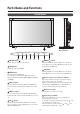
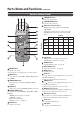
Parts Name and Functions Control Panel 9 10 Button Location EXIT 8 1 POWER button ( 7 6 5 INPUT MUTE 3 2 4 ) 1 7 DOWN ( Switches the power on/off. See also page 17. ) button Activates the OSM menu when the OSM menu is turned-off. Acts as button to move the highlighted area down to select the adjustment with OSM menu. 2 MUTE button Switches the audio mute ON/OFF. 8 EXIT button Activates the OSM menu when the OSM menu is turned-off.
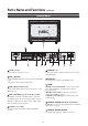
Parts Name and Functions –continued Terminal Panel 1 AC IN connector 6 AUDIO IN 1,2,3 Connects with the supplied power cord. To input audio signal from external equipment such as a computer, VCR or DVD player. 2 RGB 1 IN (DVI-D) To input digital RGB signals from a computer having a digital RGB 7 AUDIO OUT output. To output the audio signal from the AUDIO IN 3 jack. * This connector does not support analog input.
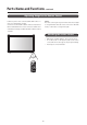
Parts Name and Functions –continued Wireless Remote Control 5 4 7 VOLUME UP button 3 Increase the audio output level. 8 VOLUME DOWN button Decrease the audio output level. 9 PIP (Picture In Picture) button 1 ON/OFF button: Toggle switches between PIP-ON/ POP-ON/OFF. INPUT button: Select the ‘picture in picture’ input signal. 2 CHANGE button: Replaces to the main picture and sub 6 9 picture.
Parts Name and Functions –continued Operating Range for the Remote Control mote sensor during button operation. Caution The remote control system may not function when direct sunlight Use the remote control within a distance of about 7 m/23 ft. from or strong illumination strikes the remote control sensor of the LCD the front of the LCD monitor's remote control sensor and at a hori- monitor, or when there is an object in the path.
Setup Procedure 1. Determine the installation location 6. Operate the attached external equipment CAUTION Display the signal on the external equipment you wish. Installing your LCD display must be done by a qualified techni- 7. Adjust the sound cian. Contact your dealer for more information. Make adjustments when adjustment of the volume is required. CAUTION 8.
Connections Before making connections: * First turn off the power of all the attached equipment and make connections. * Refer to the user manual included with each separate piece of equipment. Wiring Diagram Wiring Diagram LCD monitor Personal computer DVD player Personal computer HD or laser disc player VCR Equipment with digital interface LCD monitor (second monitor) Mounting Position of Ferrite Core Attaching the Ferrite Core Attach the Ferrite Core to PC Audio Cable and S-VIDEO Cable.
Connections –continued Connecting the LCD Monitor to a PC Connecting your computer to your LCD monitor will enable you to display your computer's screen image. Some video cards may not display an image correctly. • To connect the RGB 2 IN connector (mini D-sub 15 pin) on the LCD monitor, use the provided RGB signal cable (mini D-sub 15 pin to mini D-sub 15 pin). • To connect the RGB 3 DVD/HD IN connector (BNC) on the LCD monitor, use a signal cable (mini D-sub 15 pin to BNC x 5).
Connections –continued Connecting to a Macintosh® Computer Connecting your Macintosh® computer to your LCD monitor will enable you to display your computer's screen image. Some video cards or drivers may not display images correctly. • To connect the RGB 2 IN connector (mini D-sub 15 pin) on the LCD monitor, use the provided RGB signal cable (mini D-sub 15 pin to mini D-sub 15 pin). For older Macintosh® computers, use Macintosh cable adapter to connect to your Macintosh's video port.
Connections –continued Connecting to a Computer with a Digital Output Connections can be made with equipment that is equipped with a digital interface compliant with the DVI (Digital Visual Interface) standard. • The RGB 1 IN connector also accepts a DVI-D cable. • Input TMDS signals conforming to DVI standards. • To maintain display quality, use a cable recommended by DVI standards. • The AUDIO IN 1, 2 and 3 can be used for audio input.
Connections –continued Connecting to a VCR or Laser Disc Player Connecting your VCR or laser disc player to your LCD monitor will enable you to display your VCR or laser disc player video. Refer to your VCR or laser disc player owner's manual for more information. • Video signals can be connected to either the VIDEO IN [RCA or BNC] or the S-VIDEO IN connector. NOTE: If S-VIDEO and RCA are both connected, S-VIDEO will have priority. • Video output will be from the OUT connector that has been set here.
Connections –continued Connecting to a DVD Player Connecting your DVD player to your LCD monitor will enable you to display your DVD video. Refer to your DVD player owner’s manual for more information. To connect the RGB 3 DVD/HD In connector (BNC) on the LCD monitor, use a separately available BNC connector cable. You will need a BNC-to-RCA adapter to connect a DVD player with an RCA pin jack to the BNC connector cable (not provided).
Connections –continued Connecting to a Stereo Amplifier You can connect your stereo amplifier to your LCD monitor. Refer to your amplifier owner's manual for more information. • Turn on the LCD monitor and the amplifier only after all hookups have been made. • Use an RCA cable to connect the AUDIO OUT connector (RCA) on the LCD monitor and the audio input on the amplifier. • Do not reverse the audio left and right jacks. • The AUDIO IN 3 used for audio input.
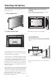
Basic Operation –Power ON and OFF Modes The LCD monitor power indicator will turn green while powered on or red in off mode. The monitor can be powered on or off using the following three options: 1. Pressing the power button. NOTE: Before operating the remote control, be sure to turn on the Main Power Switch on the LCD monitor. Power Button 2. Using the remote control NOTE: Before operating the remote control, be sure to turn on the Main Power Switch on the LCD monitor. REMOTE CONTROLLER RU-M104 3.
Basic Operation –continued Power Indicator OSM Information RGB1, 2, 3 Power Indicator Status Power ON RGB2 1024 x 768 ) 48kHz 60Hz AUDIO : 1 SCREEN SIZE : FULL Green Power OFF Red Power Standby Red and Green Video Input mode Input signal Information Audio input mode Picture Size mode DVD/HD When Using Power Management Function DVD/HD AUDIO : 3 SCREEN SIZE : WIDE The LCD monitor follows the VESA approved DPMS Power Management function.
OSM (On-Screen Manager) Controls –Computer Press UP or DOWN button to select sub-menu Press SET Press UP or DOWN, and PLUS or MINUS button to select function, or control which you like Press MENU or EXIT button to decide Remote Control SET Press UP or DOWN button to select SET SET SET Press INPUT button to decide Press UP or DOWN button to select Press INPUT button to decide Control Panel INPUT INPUT UP or DOWN button OSM screen INPUT button BRIGHTNESS BRIGHTNESS CONTRAST SHARPNESS BLACK L
OSM Controls –Computer continued BRIGHTNESS CONTRAST SHARPNESS BLACK LEVEL COLOR CONTROL COLOR TEMPERATURE PICTURE RESET COLOR TEMPERATURE COLOR TEMPERATURE L :SEL :SEL EXIT:PRE SET:NEXT MENU:END EXIT:PRE MENU:END Selecting Picture Reset allows you to reset all OSM setting about PICTURE setting.
OSM Controls –Computer continued Main-Menu PICTURE SCREEN AUDIO PICTURE IN PICTURE CONFIGURATION 1 CONFIGURATION 2 AUDIO :SEL EXIT:PRE SET:NEXT MENU:END Sub-Menu TREBLE TREBLE BASS AUDIO RESET - BASS :SEL EXIT:PRE SET:NEXT MENU:END AUDIO RESET TREBLE BASS AUDIO RESET :SEL EXIT:PRE SET:NEXT MENU:END + :SEL :SEL EXIT:PRE SET:NEXT MENU:END TREBLE BASS AUDIO RESET To accentuate or control the high frequency sound. TREBLE EXIT:PRE MENU:END Press + button to increase TREBLE sound.
OSM Controls –Computer continued AUTO BRIGHTNESS *:INPUT RGB2/3 only POWER SAVE AUTO SETUP AUTO ADJUST AUTO BRIGHTNESS POWER SAVE LANGUAGE OSM TIME OFF TIMER SCREEN SAVER FACTORY PRESET ON OFF :SEL :SEL EXIT:PRE SET:NEXT MENU:END AUTO SETUP AUTO ADJUST AUTO BRIGHTNESS POWER SAVE LANGUAGE OSM TIME OFF TIMER SCREEN SAVER FACTORY PRESET LANGUAGE OSM TIME :SEL EXIT:PRE SET:NEXT MENU:END OFF TIMER AUTO SETUP AUTO ADJUST AUTO BRIGHTNESS POWER SAVE LANGUAGE OSM TIME OFF TIMER SCREEN SAVER FACTORY PRESET
OSM Controls –DVD & HD Main-Menu PICTURE AUDIO PICTURE IN PICTURE CONFIGURATION PICTURE :SEL EXIT:PRE SET:NEXT MENU:END Sub-Menu BRIGHTNESS BRIGHTNESS CONTRAST SHARPNESS COLOR BLACK LEVEL PICTURE RESET 50 - :SEL EXIT:PRE SET:NEXT MENU:END BRIGHTNESS CONTRAST SHARPNESS COLOR BLACK LEVEL PICTURE RESET CONTRAST SHARPNESS COLOR BLACK LEVEL - Press + button to increase sharpness. Press - button to decrease sharpness.
OSM Controls –DVD & HD continued Main-Menu PICTURE IN PICTURE PICTURE AUDIO PICTURE IN PICTURE CONFIGURATION :SEL EXIT:PRE SET:NEXT MENU:END Sub-Menu Selecting the size of picture inserted at the 'Picture-in Picture' (PIP) mode. 'Large', 'Middle', and 'Small' are available.
OSM Controls –AV Input Main-Menu PICTURE AUDIO PICTURE IN PICTURE CONFIGURATION PICTURE :SEL EXIT:PRE SET:NEXT MENU:END Sub-Menu BRIGHTNESS BRIGHTNESS CONTRAST SHARPNESS TINT COLOR BLACK LEVEL NOISE REDUCTION PICTURE RESET 50 - + :SEL :SEL EXIT:PRE SET:NEXT MENU:END BRIGHTNESS CONTRAST SHARPNESS TINT COLOR BLACK LEVEL NOISE REDUCTION PICTURE RESET CONTRAST SHARPNESS - :SEL BLACK LEVEL NOISE REDUCTION 50 + :SEL PICTURE RESET EXIT:PRE MENU:END :SEL EXIT:PRE MENU:END + :SEL Press +
OSM Controls –AV Input continued TREBLE BASS AUDIO RESET BASS To accentuate or control the low frequency sound. BASS - :SEL EXIT:PRE SET:NEXT MENU:END + :SEL EXIT:PRE MENU:END Selecting Picture Reset allows you to reset all OSM settings from AUDIO setting. AUDIO RESET TREBLE BASS AUDIO RESET NO YES AUDIO RESET :SEL EXIT:PRE SET:NEXT MENU:END :SEL EXIT:PRE Press + button to increase BASS sound. Press - button to decrease BASS sound.
OSM Controls –AV Input continued COLOR SYSTEM LANGUAGE OSM TIME OFF TIMER SCREEN SAVER COLOR SYSTEM CONFIGURATION RESET Selecting the Color System depends on your input video format. COLOR SYSTEM PAL SECAM NTSC is automatic.
Using the LCD with a Personal Computer (PC) This LCD monitor can be controlled by connecting a personal computer with a RS-232C terminal. Functions that can be controlled by a personal computer are: • Power ON or OFF • Switching between input signals Connection LCD Monitor + PC PC to RS-232C terminal RS-232C Cable Note: If your PC (IBM or IBM compatible) is equipped only with a 25-pin serial port connector, a 25-pin serial port adapter is required. Contact your dealer for details.
Using the LCD with a Personal Computer –continued 3) Control sequence (1) The command from a personal computer to the LCD monitor will be sent in 400ms. (2) The LCD monitor will send a return command 400ms* after it has received an encode. If the command isn't received correctly, the LCD monitor will not send the return command. (3) The personal computer checks the command and confirms if the command which has been sent has been executed or not.
Features 40” diagonal screen size adds a new option to information display visual offerings. 1280 x 768 resolution allows for crisp text and precise images. No permanent phosphor image burn-in contributes to optimal screen performance and longer monitor life. XtraView® technology allows for wide-angle viewing. DDC/CI capabilities allow control commands to be sent directly to the monitor through a standard PC or over an existing network by a system administrator.
Troubleshooting No picture • The signal cable should be completely connected to the display card/computer. • The display card should be completely seated in its slot. • Front Power Switch and computer power switch should be in the ON position. • Check to make sure that a supported mode has been selected on the display card or system being used. (Please consult display card or system manual to change graphics mode.
References NEC-Mitsubishi Monitor Customer Service & Support Customer Service and Technical Support: Fax: Parts and Accessories/Macintosh Cable Adapter: Customer Service Policies & Processes: Online Technical Support Knowledge Base: Customer Service & Technical Support Email: (800) 632-4662 (800) 695-3044 (888) NEC-MITS [888-632-6487] http://www.necmitsubishi.com/ css/ ServicePolicies/ServicePolicies.htm http://www.necmitsubishi.com/css/ knowledgebase.cfm http://www.necmitsubishi.com/css/ techform.
Specifications Analog Input LCD Module Digital Input (40" / 101.6cm diagonal) Pixel Pitch 0.681mm Resolution 1280 x 768 dots (WXGA) Color Over 16 million colors Brightness 450cd/m2 (Typ.) Viewing Angle Up 85 / Down 85 / Left 85 / Right 85 (typ) @ CR >10 External speaker output inpedance Rating 7W x 7W (8 Ohm) Frequency Horizontal 31.5kHz - 75.0kHz (15.75kHz) 31.5kHz - 48.4kHz Vertical 58.0 - 62.0 Hz 58.0 - 62.0 Hz Pixel Clock 25.0MHz - 162.0MHz 25.0MHz - 65.0MHz Viewable Size 871.
Limited Warranty NEC-Mitsubishi Electronics Display of America, Inc. (hereinafter “NMD-A”) warrants this Product to be free from defects in material and workmanship and, subject to the conditions set forth below, agrees to repair or replace (at NMD-A’s sole option) any part of the enclosed unit which proves defective for a period of one (1) year from the date of first consumer purchase. Spare parts are warranted for ninety (90) days.
Declaration of the Manufacturer We hereby certify that the color monitors LCD4000 is in compliance with Council Directive 73/23/EEC: – EN 60950 Council Directive 89/336/EEC: — EN 55022 — EN 61000-3-2 — EN 61000-3-3 — EN 55024 and marked with NEC-Mitsubishi Electric Visual Systems Corporation 4-13-23, Shibaura, Minato-Ku Tokyo 108-0023, Japan
NEC LCD4000 PROPRIETARY NOTICE AND LIABILITY DISCLAIMER The information disclosed in this document, including all designs and related materials, is the valuable property of NEC-Mitsubishi Electronics Display of America and/or its licensors, as appropriate, reserve all patent, copyright and other proprietary rights to this document, including all design, manufacturing, reproduction, use and sales rights thereto, except to the extent said rights are expressly granted to others.