English Français
Important Information .......................................................................................................................... English-2 Safety Precautions, Maintenance, & Recommended Use ................................................................ English-3 Contents .................................................................................................................................................... English-4 Attaching LCD Options .........................................
Important Information WARNING TO PREVENT FIRE OR SHOCK HAZARDS, DO NOT EXPOSE THIS UNIT TO RAIN OR MOISTURE. ALSO, DO NOT USE THIS UNIT'S POLARIZED PLUG WITH AN EXTENSION CORD RECEPTACLE OR OTHER OUTLETS UNLESS THE PRONGS CAN BE FULLY INSERTED. REFRAIN FROM OPENING THE CABINET AS THERE ARE HIGH VOLTAGE COMPONENTS INSIDE. REFER SERVICING TO QUALIFIED SERVICE PERSONNEL. CAUTION CAUTION:TO REDUCE THE RISK OF ELECTRIC SHOCK, MAKE SURE POWER CORD IS UNPLUGGED FROM WALL SOCKET.
Safety Precautions, Maintenance & Recommended Use FOR OPTIMUM PERFORMANCE, PLEASE NOTE THE FOLLOWING WHEN SETTING UP AND USING THE LCD4000e LCD COLOR MONITOR: • DO NOT OPEN THE MONITOR. There are no user serviceable parts inside and opening or removing covers may expose you to dangerous shock hazards or other risks. Refer all servicing to qualified service personnel. • Do not spill any liquids into the cabinet or use your monitor near water.
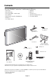
Contents Your new LCD4000e™ monitor box* should contain the following: • • • • • • • LCD monitor Power Cord (3m) Video Signal Cable – SC-B113 (4m) User’s Manual Wireless Remote Control and AA Batteries Clamper x 2 Screw (M4 x 10) x 2 • • • • • CD-ROM Band x 3 Ferrite Core x 4 Stand for the Independence x 2 Screw (M5 x 40) x 4 Stand for the Independence x 2 Screw (M5 x 40) for stand x 4 Power Cord Video Signal Cable (D-SUB to D-SUB Cable) Clamper x 2 Screw (M4 x 10 ) x 2 Ferrite Core x 4 CD-ROM User’
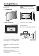
Ventilation Requirements for enclosure mounting You can attach mounting accessories to the LCD monitor in one of the following two ways: To allow heat to disperse, leave space between surrounding 1. In the upright position objects as shown in the diagram to the right. * 2.
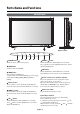
Parts Name and Functions Control Panel 9 10 Button Location EXIT INPUT 8 1 POWER button ( 7 6 5 4 3 ) 2 7 Switches the power on/off. See also page 18. 2 MUTE DOWN ( 1 ) button Activates the OSM menu when the OSM menu is turned-off. Acts as button to move the highlighted area down to select the adjustment with OSM menu. MUTE button Switches the audio mute ON/OFF. 8 3 EXIT button Activates the OSM menu when the OSM menu is turned-off. INPUT button Acts as SET button with OSM menu.
Parts Name and Functions –continued English Terminal Panel 1 AC IN connector 6 Connects with the supplied power cord. AUDIO IN 1,2,3 To input audio signal from external equipment such as a computer, VCR or DVD player. 2 RGB 1 IN (DVI-D) AUDIO OUT To input digital RGB signals from a computer having a digital RGB 7 output. To output the audio signal from the AUDIO IN 3 jack. * This connector does not support analog input.
Parts Name and Functions –continued Wireless Remote Control VOLUME UP button 7 Increase the audio output level. VOLUME DOWN button 8 Decrease the audio output level. PIP (Picture In Picture) button 9 ON/OFF button: Toggle switches between PIP-ON/ POP-ON/OFF. INPUT button: Select the ‘picture in picture’ input signal. CHANGE button: Replaces to the main picture and sub Main Picture picture.
Parts Name and Functions –continued Point the top of the remote control toward the LCD monitor's remote Caution sensor during button operation. Use the remote control within a distance of about 7 m/23 ft. from The remote control system may not function when direct sunlight or the front of the LCD monitor's remote control sensor and at a hori- tor, or when there is an object in the path.
Setup Procedure 1. Determine the installation location CAUTION 5. Switch on the power of all the attached external equipment Installing your LCD display must be done by a qualified technician. When connected with a computer, switch on the power of the com- Contact your dealer for more information. puter first. 6. Operate the attached external equipment CAUTION MOVING OR INSTALLING THE LCD MONITOR MUST BE DONE BY TWO OR MORE PEOPLE.
Connections * First turn off the power of all the attached equipment and make connections. * Refer to the user manual included with each separate piece of equipment. English Before making connections: Wiring Diagram Wiring Diagram Mounting Position of Ferrite Core Attaching the Ferrite Core Attach the Ferrite Core to PC Audio Cable and S-VIDEO Cable. Use of the cable without mounting the ferrite core will result in the occurrence of noise.
Connections –continued Connecting the LCD Monitor to a PC Connecting your computer to your LCD monitor will enable you to display your computer's screen image. Some video cards may not display an image correctly. • To connect the RGB 2 IN connector (mini D-sub 15 pin) on the LCD monitor, use the provided RGB signal cable (mini D-sub 15 pin to mini D-sub 15 pin). • To connect the RGB 3 DVD/HD IN connector (BNC) on the LCD monitor, use a signal cable (mini D-sub 15 pin to BNC x 5).
Connections –continued Connecting your Macintosh® computer to your LCD monitor will enable you to display your computer's screen image. Some video cards or drivers may not display images correctly. • To connect the RGB 2 IN connector (mini D-sub 15 pin) on the LCD monitor, use the provided RGB signal cable (mini D-sub 15 pin to mini D-sub 15 pin). For older Macintosh® computers, use Macintosh cable adapter to connect to your Macintosh's video port.
Connections –continued Connecting to a Computer with a Digital Output Connections can be made with equipment that is equipped with a digital interface compliant with the DVI (Digital Visual Interface) standard. • The RGB 1 IN connector also accepts a DVI-D cable. • Input TMDS signals conforming to DVI standards. • • To maintain display quality, use a cable recommended by DVI standards. The AUDIO IN 1, 2 and 3 can be used for audio input.
Connections –continued Connecting your VCR or laser disc player to your LCD monitor will enable you to display your VCR or laser disc player video. Refer to your VCR or laser disc player owner's manual for more information. • Video signals can be connected to either the VIDEO IN [RCA or BNC] or the S-VIDEO IN connector. NOTE: If S-VIDEO and RCA are both connected, S-VIDEO will have priority. • Video output will be from the OUT connector that has been set here.
Connections –continued Connecting to a DVD Player Connecting your DVD player to your LCD monitor will enable you to display your DVD video. Refer to your DVD player owner’s manual for more information. • To connect the RGB 3 DVD/HD In connector (BNC) on the LCD monitor, use a separately available BNC connector cable. You will need a BNC-to-RCA adapter to connect a DVD player with an RCA pin jack to the BNC connector cable (not provided).
Connections –continued You can connect your stereo amplifier to your LCD monitor. Refer to your amplifier owner's manual for more information. • • Turn on the LCD monitor and the amplifier only after all hookups have been made. Use an RCA cable to connect the AUDIO OUT connector (RCA) on the LCD monitor and the audio input on the amplifier. • Do not reverse the audio left and right jacks. • • The AUDIO IN 3 used for audio input. The AUDIO OUT jack outputs sound for the AUDIO IN 3 only.
Basic Operation –Power ON and OFF Modes The LCD monitor power indicator will turn green while powered on or red in off mode. The monitor can be powered on or off using the following three options: 1. Pressing the power button. NOTE: Before operating the remote control, be sure to turn on the Main Power Switch on the LCD monitor. Power Button 2. Using the remote control NOTE: Before operating the remote control, be sure to turn on the Main Power Switch on the LCD monitor. REMOTE CONTROLLER RU-M104 3.
–continued Power Indicator OSM Information Power Indicator RGB1, 2, 3 Status Power ON Power OFF Green Red Power Standby Red and Green RGB2 1024 x 768 ) 48kHz 60Hz AUDIO : 1 SCREEN SIZE : FULL Video Input mode Input signal Information Audio input mode Picture Size mode DVD/HD When Using Power Management Function DVD/HD AUDIO : 3 SCREEN SIZE : WIDE The LCD monitor follows the VESA approved DPMS Power Management function.
OSM® (On-Screen Manager) Controls –Computer Press UP or DOWN button to select sub-menu Press SET Press UP or DOWN, and PLUS or MINUS button to select function, or control which you like Press MENU or EXIT button to decide Remote Control SET Press UP or DOWN button to select SET SET SET Press INPUT button to decide Press UP or DOWN button to select Press INPUT button to decide Control Panel INPUT INPUT UP or DOWN button OSM screen INPUT button BRIGHTNESS BRIGHTNESS CONTRAST SHARPNESS BLACK
BRIGHTNESS CONTRAST SHARPNESS BLACK LEVEL COLOR CONTROL COLOR TEMPERATURE PICTURE RESET COLOR TEMPERATURE COLOR TEMPERATURE L :SEL :SEL EXIT:PRE SET:NEXT MENU:END EXIT:PRE MENU:END Selecting Picture Reset allows you to reset all OSM setting about PICTURE setting. PICTURE RESET BRIGHTNESS CONTRAST SHARPNESS BLACK LEVEL COLOR CONTROL COLOR TEMPERATURE PICTURE RESET PICTURE RESET H NO YES :SEL :SEL EXIT:PRE SET:NEXT MENU:END EXIT:PRE To adjust the color temperature of entire screen.
OSM Controls –Computer continued Main-Menu PICTURE SCREEN AUDIO PICTURE IN PICTURE CONFIGURATION 1 CONFIGURATION 2 AUDIO :SEL EXIT:PRE SET:NEXT MENU:END Sub-Menu TREBLE TREBLE BASS AUDIO RESET - BASS :SEL EXIT:PRE SET:NEXT MENU:END AUDIO RESET TREBLE BASS AUDIO RESET :SEL EXIT:PRE SET:NEXT MENU:END + :SEL :SEL EXIT:PRE SET:NEXT MENU:END TREBLE BASS AUDIO RESET To accentuate or control the high frequency sound. TREBLE EXIT:PRE MENU:END Press + button to increase TREBLE sound.
AUTO BRIGHTNESS *:INPUT RGB2/3 only POWER SAVE AUTO SETUP AUTO ADJUST AUTO BRIGHTNESS POWER SAVE LANGUAGE OSM TIME OFF TIMER SCREEN SAVER FACTORY PRESET ON OFF :SEL :SEL EXIT:PRE SET:NEXT MENU:END AUTO SETUP AUTO ADJUST AUTO BRIGHTNESS POWER SAVE LANGUAGE OSM TIME OFF TIMER SCREEN SAVER FACTORY PRESET LANGUAGE OSM TIME :SEL EXIT:PRE SET:NEXT MENU:END OFF TIMER AUTO SETUP AUTO ADJUST AUTO BRIGHTNESS POWER SAVE LANGUAGE OSM TIME OFF TIMER SCREEN SAVER FACTORY PRESET :SEL EXIT:PRE SET:NEXT MENU:END
OSM Controls –DVD & HD Main-Menu PICTURE AUDIO PICTURE IN PICTURE CONFIGURATION PICTURE :SEL EXIT:PRE SET:NEXT MENU:END Sub-Menu BRIGHTNESS BRIGHTNESS CONTRAST SHARPNESS COLOR BLACK LEVEL PICTURE RESET 50 - :SEL EXIT:PRE SET:NEXT MENU:END BRIGHTNESS CONTRAST SHARPNESS COLOR BLACK LEVEL PICTURE RESET CONTRAST SHARPNESS COLOR BLACK LEVEL Press + button to increase brightness. Press - button to decrease brightness.
OSM Controls –DVD & HD continued PICTURE IN PICTURE PICTURE AUDIO PICTURE IN PICTURE CONFIGURATION :SEL EXIT:PRE SET:NEXT MENU:END Sub-Menu Selecting the size of picture inserted at the 'Picture-in-Picture' (PIP) mode. 'Large', 'Middle', and 'Small' are available.
OSM Controls –AV Input Main-Menu PICTURE AUDIO PICTURE IN PICTURE CONFIGURATION PICTURE :SEL EXIT:PRE SET:NEXT MENU:END Sub-Menu BRIGHTNESS BRIGHTNESS CONTRAST SHARPNESS TINT COLOR BLACK LEVEL NOISE REDUCTION PICTURE RESET 50 - + :SEL :SEL EXIT:PRE SET:NEXT MENU:END BRIGHTNESS CONTRAST SHARPNESS TINT COLOR BLACK LEVEL NOISE REDUCTION PICTURE RESET CONTRAST SHARPNESS - :SEL BLACK LEVEL NOISE REDUCTION 50 + :SEL PICTURE RESET EXIT:PRE MENU:END :SEL EXIT:PRE MENU:END + :SEL Press +
TREBLE BASS AUDIO RESET BASS To accentuate or control the low frequency sound. BASS - :SEL EXIT:PRE SET:NEXT MENU:END + :SEL EXIT:PRE MENU:END Selecting Audio Reset allows you to reset all OSM settings from AUDIO setting. AUDIO RESET TREBLE BASS AUDIO RESET NO YES AUDIO RESET :SEL EXIT:PRE SET:NEXT MENU:END :SEL EXIT:PRE Press + button to increase BASS sound. Press - button to decrease BASS sound. MENU:END Select "Yes" and press "SET" button to decide to restore to factory preset.
OSM Controls –AV Input continued English-28
Using the LCD with a Personal Computer (PC) English This LCD monitor can be controlled by connecting a personal computer with a RS-232C terminal. Functions that can be controlled by a personal computer are: • Power ON or OFF • Switching between input signals Connection LCD Monitor + PC PC to RS-232C terminal RS-232C Cable Note: If your PC (IBM or IBM compatible) is equipped only with a 25-pin serial port connector, a 25-pin serial port adapter is required. Contact your dealer for details.
Using the LCD with a Personal Computer –continued 3) Control sequence (1) The command from a personal computer to the LCD monitor will be sent in 400ms. (2) The LCD monitor will send a return command 400ms* after it has received an encode. If the command isn't received correctly, the LCD monitor will not send the return command. (3) The personal computer checks the command and confirms if the command which has been sent has been executed or not.
Features 1280 x 768 resolution allows for crisp text and precise images. No permanent phosphor image burn-in contributes to optimal screen performance and longer monitor life. XtraView® technology allows for wide-angle viewing. DDC/CI capabilities allow control commands to be sent directly to the monitor through a standard PC or over an existing network by a system administrator. CableComp™ automatic long cable compensation prevents image quality degradation caused by long cable lengths.
Troubleshooting No picture • The signal cable should be completely connected to the display card/computer. • The display card should be completely seated in its slot. • • Front Power Switch and computer power switch should be in the ON position. Check to make sure that a supported mode has been selected on the display card or system being used. (Please consult display card or system manual to change graphics mode.
References Customer Service and Technical Support: Fax: Parts and Accessories/Macintosh Cable Adapter: Customer Service Policies & Processes: Online Technical Support Knowledge Base: Customer Service & Technical Support Email: (800) 632-4662 (800) 695-3044 (888) NEC-MITS [888-632-6487] http://www.necmitsubishi.com/css/ ServicePolicies/ServicePolicies.htm http://www.necmitsubishi.com/css/ knowledgebase.cfm http://www.necmitsubishi.com/css/ techform.
Specifications Analog Input LCD Module Digital Input 40" (39.6" active display area) / 100.5cm diagonal Pixel Pitch 0.673mm Resolution 1280 x 768 dots (WXGA) Color 16,777,216 colors (depending on video card used) Brightness 450cd/m2 (Typ.) Contrast ratio 600 : 1 Viewing Angle Up 85°/ Down 85°/ Left 85°/ Right 85° (typ) @ CR >10 External speaker output inpedance Rating 7W x 7W (8 Ohm) Frequency Horizontal 31.5kHz - 49.0kHz, 64.0kHz: SXGA, 75.0kHz: UXGA 31.5kHz - 48.
NEC-Mitsubishi Electronics Display of America, Inc. (hereinafter “NMD-A”) warrants this Product to be free from defects in material and workmanship and, subject to the conditions set forth below, agrees to repair or replace (at NMD-A’s sole option) any part of the enclosed unit which proves defective for a period of one (1) year from the date of first consumer purchase. Spare parts are warranted for ninety (90) days.
Declaration of the Manufacturer We hereby certify that the color monitor LCD4000e (L403FU) is in compliance with Council Directive 73/23/EEC: – EN 60950 Council Directive 89/336/EEC: — EN 55022 — EN 61000-3-2 — EN 61000-3-3 — EN 55024 and marked with NEC-Mitsubishi Electric Visual Systems Corporation 4-13-23, Shibaura, Minato-Ku Tokyo 108-0023, Japan
NEC LCD4000e PROPRIETARY NOTICE AND LIABILITY DISCLAIMER The information disclosed in this document, including all designs and related materials, is the valuable property of NEC-Mitsubishi Electronics Display of America and/or its licensors, as appropriate, reserve all patent, copyright and other proprietary rights to this document, including all design, manufacturing, reproduction, use and sales rights thereto, except to the extent said rights are expressly granted to others.
Informations importantes ..................................................................................................................... Franchçais-2 Consignes de sécurité, d’entretien, et conseils d’utilisation ........................................................ Franchçais-3 Sommaire .................................................................................................................................................. Franchçais-4 Comment moniter et branch des accessoires au moniteur .
Informations Importantes AVERTISSEMENT AFIN D’ÉVITER TOUT RISQUE D’INCENDIE OU D’ÉLECTROCUTION, NE PAS EXPOSER CET APPAEIL À LA PLUIE OU À L’ HUMIDITÉ. NE PAS UTILISER LA FICHE D’ ALIMENTATION POLARISÉE AVEC UNE PRISE DE CORDON DE RALLONGE OU AUTRE PRISE SAUF SI LES BROCHES PEUVENT ÊTRE ENTIÈREMENT INTRODUITES. NE PAS OUVRIR LE BOÎTIER, LEQUEL CONTIENT DES COMPOSANTS À HAUTE TENSION. CONFIER TOUS TRAVAUX À DU PERSONNEL TECHNQUE QUALIFIÉ.
Consignes de sécurité, d’entretion et conseils d’utilisation POUR UN FONCTIONNEMENT OPTIMAL, VEUILLEZ RESPECTER LES INDICATIONS SUIVANTES SUR LE RÉGLAGE ET L’UTILISATION DU MONITEUR LCD COULEUR LCD4000e : • N’OUVREZ JAMAIS LE BOÏTIER DU MONITUR. Aucune pièce interne ne peut être réparé et l’ouverture ou la dépose des capots peut vous exposer á des risques de décharges électriques ou autres. Confiez toutes les interventions de dépannage à un personnel technique qualifié.
Sommaire La boîte* de votre nouveau moniteur LCD LCD4000e doit contenir les éléments suivants : • Moniteur LCD4000e • Cordon d’alimentation (3 m) • • • • • Câble de signal • Manuel de l’utilisateur • Télécommande sans-fil et piles AA • Serre-fils x 2 Sangle x 3 Noyau de ferrite x 4 Support pour l’autonomie x 2 Vis (M5 x 40) pour support x 4 • Vis (M4 x 10) x 2 • CD-ROM Vis (M5 x 40) pour support x 4 Support pour l’autonomie x 2 Cordon d’alimentation Câble de signal Vis (M4 x 10 ) x 2 Serre-fils x
Comment monter et brancher des accessoires au moniteur Vous pouvez brancher des accessoires de montage sur le moniteur Ventilation en vous y prenant de l’une des maniéres suivantes: pour permettre à la chaleur de se disperser, laissez de l’espace entre les objets environnants comme dans la partie droite du 1. En posicion verticale schéma. Français * 2.
Noms et fonctions des piéces Panneau de commande Buttons 1 Bouton d’ alimentation ( ) 7 2 Bouton BAS ( ) Réactive le menu OSM lorsque celui-ci est désactivé. Joue dans le menu OSM le rôle de de bouton pour déplacer vers le bas la zone en surbrillance et sélectionner le réglage. Allume et éteint l’appareil. Voir également page 18. Bouton MUTE Coupe ou rétablit le son. 8 3 Bouton INPUT Joue dans le menu OSM le rôle de bouton SET. Sélctionne le signal connecté avec le connecteur d’entrée RVB.
Noms et fonctions des piéces Français Panneau des connexions 1 Prise CA IN 6 Se connecte au cordon d’alimentation fourni avec le moniteur. AUDIO IN 1,2,3 Pour recevoir le signal audio provenant d’un matériel externe, ordinateur, magnétoscope ou lecteur de DVD. 2 RVB 1 IN (DVI-D) Pour recevoir des signaux RVB numériques provenant d’un ordinateur disposant d’une sortie RVB numérique. 7 AUDIO OUT Pour émettre le signal audio provenant du jack AUDIO IN 3.
Noms et fonctions des piéces Télécommande sans-fil 6 Bouton MUTE Pour couper ou rétablir le son. 7 Bouton VOLUME UP Augmente le niveau de la sortie sonore. 8 Bouton VOLUME DOWN Diminue le niveau de la sortie sonore. 9 Bouton PIP (Picture In Picture) Bouton ON/OFF : Bascule entre PIP-ON/POP-ON/OFF. Bouton INPUT : Sélectionner le signal ”image dans l’image”. Bouton CHANGE : Remplace par l’image principale et la sous-image. 10 Bouton STILL Bouton ON/OFF : Pour activer ou désactiver le mode image.
Noms et fonctions des piéces Distance d’utilisation de la télécommande Manipulation de la télécommande Pointez pendant le réglage des boutons le haut de la télécommande en direction du capteur à distance du moniteur. Utilisez la télécommande à une distance d’environ 7 m de l’avant du capteur à distance et à un angle horizontal et vertical de 30° à * Evitez de soumettre la télécommande à des chocs violents. * Evitez d’asperger la télécommande avec de l’eau ou d’autres liquides.
Installation 1. Choix de l’emplacement du moniteur ATTENTION : L’installation de l’écran doit être effectuée par un technicien qualifié. Prenez contact avec votre revendeur. ATTENTION :IL FAUT AU MOINS DEUX PERSONNES POUR DEPLACER OU INSTALLER LE MONITEUR. REMARQUE : Si vous utilisez ce moniteur à AC220-240V, s’il vous plaît faites référence à section de l’Consignes de securite, d’entretien, et conseils d’utilisation de ce manuel pour sélection adéquate d’AC pouvoir cordon. 5.
Connexions Avant d’effectuer les branchments: * Commencez par mettre hors tension tous les matériels à brancher au moniteur. * Consultez la documentation fournie avec ces matériels. Wiring Diagram Français Schéma de câblage Position de montage du noyau de ferrite Fixation de la Noyau de ferrite Fixer le noyau de ferrite au câble audio du PC et au câble S-VIDEO. L'utilisation du Câble sans fixer le noyau de ferrite provoquera l'apparition de bruit.
Connexions à un PC Connexion du moniteur à un PC La connexion d’un PC à votre moniteur vous permettra d’afficher l’image présente sur l’écran de votre micro-ordinateur. Certaines cartes vidéo risquent de ne pas être capables de créer une résolution correcte. • Pour connecter la prise RVB 2 IN (mini D-sub 15 broches) du moniteur, utilisez le câble vidéo RVB qui est fourni avec le matériel (mini D-sub 15 broches vers mini d-sub 15 broches).
Connexions à un Macintosh® Connexion du moniteur au Macintosh ® La connexion d’un Macintosh® à votre moniteur vous permettra d’afficher l’image présente sur l’écran de votre ordinnateur. Certaines cartes ou certains pilotes vidéo risquent de ne pas afficher correctement les images. • Pour connecter la prise RVB 2 IN (mini D-sub 15 broches) du moniteur, utilisez le câble vidéo RVB qui est fourni avec le matériel (mini D-sub 15 broches vers mini D-sub 15 broches).
Connexions avec du matériel à interface numérique Connexion du moniteur à un ordinateur équipé d’une sortie numérique ll est possible d’établir des connexions avec du matériel équipé d’une interface numérique compatible DVI (Digital Visual Interface). • • La prise RVB 1 IN accepte également les câbles DVI-D. En entrée, des signaux TMDS conformes à la norme DVI. • Pour préserver la qualité de l’affichage, utilisez un câble conforme aux normes DVI de qualité.
Connexion d’un magnétoscope Connexion du moniteur à un magnétoscope ou à lecteur de disques laser La connexion au moniteur d’un magnétoscope ou d’un lecteur de disques laser vous permettra d’afficher la vidéo de vos cassettes ou de vos disques laser. Consultez la documentation fournie avec votre magnétoscope ou votre lecteur de disques laser. • Les signaux vidéo peuvent se connecter soit à la prise VIDEO IN [RCA ou BNC], soir à prise S-VIDEO IN. REMARQUE: S-VIDEO est l’entrée prioritaire.
Connexion d’un lecteur de DVD Connexion du moniteur à un lecteur de DVD La conexion au moniteur d’un lecteur de DVD vous permettra d’afficher la vidéo de vos DVD. Consultez la documentation de votre lecteur de DVD. • Pour connecter la prise RVB 3 DVD/HD ln (BNC) du moniteur, procurez-vous un câble de connexion BNC. Vous aurez besoin de vous procurer un adaptateur BNC-RCA pour connecter au câble BNC un lecteur de DVD doté d’un jack RCA à broches.
Connexion d’un amplificateur stéréo Connexion du moniteur à un amplificateur stéréo Vous pouvez connecter un amplificateur stéréo au moniteur. Consultez la documentation de votre ampli. Ne mettez le moniteur et l’amplificateur sous tension qu’aprés avoir effectué tous les branchements. Utilisez un câble RCA pour connecter la prise AUDIO OUT (RCA) du moniteur et l’entrée audio de l’amplificateur. • N’inversez pas les jacks audio gauche et droite. • • La prise AUDIO IN sert à l’entrée audio.
Opération de base L’indicateur d’alimentation du moniteur passe au vert lorsque ce dernier est sous tension, et au rouge lorsque le moniteur est en mode ARRÊT. ll existe trois maniéres d’allumer et d’éteindre le moniteur. 1. En appuyant sur le bouton d’alimentation. Remarque: Avant d’utiliser la télécommande, vérifiez que l’interrupteur principal d’alimentation du moniteur est bien en position MARCHE. Interrupteur d’ alimentation 2. A l’aide de la télécommande.
When Using Power Management Function Opération de base Indicateur d’alimentation Informations OSM RVB1, 2, 3 Position MARCHE Statut Vert Position ARRÊT Rouge Position VEILLE Rouge et vert RGB2 1024 x 768 ) 48kHz 60Hz AUDIO : 1 SCREEN SIZE : FULL Gestion de l’énergie Mode entrée vidéo Informations signal en entrée Mode entrée audio Mode Taille image DVD/HD de l’énergie approuvées par le VESA.
Commandes OSM (On-Screen-Manager)-Entrée ordinateur Appuyez sur les boutons HAUT ou BAS pour sélectionner un sous-menu. Télécommande SET Appuyez sur les boutons HAUT ou BAS pour sélectionner un sous-menu. Appuyez sur les boutons HAUT ou BAS, et PLUS ou MOINS pour sélectionner la fonction ou la commande qui vous intéressent. Appuyez sur le bouton SET(fixer) pour faire votre choix. Appuyez sur le bouton INPUT pour faire votre choix.
Commandes OSM (On-Screen-Manager)-Entrée ordinateur CONTRÔLE COULEURS R Y G C B M S 0 0 0 0 0 0 0 :SEL :SEL EXIT:PRE SET:NEXT MENU:END TEMPÉRATURE DES COULEURS LUMINOSITÉ CONTRASTE NETTETÉ NIVEAU DE NOIR CONTRÔLE COULEURS TEMPÉRATURE COULEURS RÉINITIAL. IMAGE MENU:END TEMPÉRATURE COULEURS L H :SEL :SEL EXIT:PRE SET:NEXT MENU:END RÉINITIALISATION IMAGE EXIT:PRE LUMINOSITÉ CONTRASTE NETTETÉ NIVEAU DE NOIR CONTRÔLE COULEURS TEMPÉRATURE COULEURS RÉINITIAL.
Commandes OSM (On-Screen-Manager)-Entrée ordinateur Menu principal IMAGE ÉCRAN AUDIO IMAGE DANS IMAGE CONFIGURATION 1 CONFIGURATION 2 AUDIO Sous-menu :SEL EXIT:PRE SET:NEXT MENU:END AIGUS GRAVES RÉINITIAL. AUDIO AIGUS - GRAVES :SEL EXIT:PRE SET:NEXT MENU:END RÉINITIAL. AUDIO AIGUS GRAVES RÉINITIAL. AUDIO :SEL EXIT:PRE SET:NEXT MENU:END + :SEL :SEL EXIT:PRE SET:NEXT MENU:END AIGUS GRAVES RÉINITIAL. AUDIO Pour accentuer ou réduire le son hautes fréquences.
Commandes OSM (On-Screen-Manager)-Entrée ordinateur Sélection de la marche/arrêt de l’économie d’énergie. INSTALLATION AUTO. RÉGLAGE AUTO. LUMINOSITÉ AUTO. ÉCONOMIE D’ÉNERGIE LANGUE DURÉE OSM PROGRAMMATEUR ARRÊT ÉCONOMISEUR ÉCRAN PRÉRÉGLAGE USINE ÉCONOMIE D’ÉNERGIE MARCHE ARRÊT :SEL :SEL EXIT:PRE SET:NEXT MENU:END INSTALLATION AUTO. RÉGLAGE AUTO. LUMINOSITÉ AUTO.
Commandes OSM (On-Screen-Manager)-Entrée DVD & HD Menu principal IMAGE AUDIO IMAGE DANS IMAGE CONFIGURATION IMAGE Sous-menu :SEL EXIT:PRE SET:NEXT MENU:END LUMINOSITÉ CONTRASTE NETTETÉ COULEUR NIVEAU DE NOIR RÉINITIAL. IMAGE LUMINOSITÉ 50 - + :SEL EXIT:PRE SET:NEXT MENU:END LUMINOSITÉ CONTRASTE NETTETÉ COULEUR NIVEAU DE NOIR RÉINITIAL.
Commandes OSM (On-Screen-Manager)-Entrée DVD & HD Menu principal IMAGE AUDIO IMAGE DANS IMAGE CONFIGURATION IMAGE DANS IMAGE Sous-menu :SEL EXIT:PRE SET:NEXT MENU:END Il est possible de choisir parmi les options suivantes la taille de l’image insérée en mode Image dans image (IDI) : « GRAND », « MOYEN » et « PETIT ». TAILLE IDI TAILLE IDI GRAND MOYEN PETIT :SEL EXIT:PRE SET:NEXT MENU:END :SEL EXIT:PRE MENU:END Sélection de la source sonore en mode IDI.
Commandes OSM (On-Screen-Manager)-Entrée AV Menu principal IMAGE AUDIO IMAGE DANS IMAGE CONFIGURATION IMAGE Sous-menu LUMINOSITÉ :SEL EXIT:PRE SET:NEXT MENU:END LUMINOSITÉ CONTRASTE NETTETÉ TEINTE COULEUR NIVEAU DE NOIR RÉDUCTION DU BRUIT RÉINITIAL. IMAGE 50 - + :SEL :SEL EXIT:PRE SET:NEXT MENU:END CONTRASTE LUMINOSITÉ CONTRASTE NETTETÉ TEINTE COULEUR NIVEAU DE NOIR RÉDUCTION DU BRUIT RÉINITIAL.
Commandes OSM (On-Screen-Manager)-Entrée AV Menu principal IMAGE AUDIO IMAGE DANS IMAGE CONFIGURATION AUDIO Sous-menu :SEL EXIT:PRE SET:NEXT MENU:END AIGUS GRAVES EXIT:PRE Pour accentuer ou réduire le son basses fréquences. - + :SEL EXIT:PRE Cette option permet de restaurer tous les réglages OSM relatifs au son. NON OUI :SEL :SEL EXIT:PRE SET:NEXT MENU:END EXIT:PRE Appuyez sur le bouton + pour augmenter les graves. Appuyez sur le bouton - pour diminuer les graves. MENU:END RÉINITIAL.
Commandes OSM (On-Screen-Manager)-Entrée AV PROGRAMMATEUR D’ARRET LANGUE DURÉE OSM PROGRAMMATEUR ARRÊT ÉCONOMISEUR ÉCRAN SYSTÈME DE COULEUR RÉINITIAL. CONFIG. :SEL EXIT:PRE SET:NEXT MENU:END ÉCONOMISEUR ÉCRAN LANGUE DURÉE OSM PROGRAMMATEUR ARRÊT ÉCONOMISEUR ÉCRAN SYSTÈME DE COULEUR RÉINITIAL. CONFIG. :SEL EXIT:PRE SET:NEXT MENU:END SYSTÈME DE COULEUR LANGUE DURÉE OSM PROGRAMMATEUR ARRÊT ÉCONOMISEUR ÉCRAN SYSTÈME DE COULEUR RÉINITIAL. CONFIG. :SEL EXIT:PRE SET:NEXT MENU:END RÉINITIAL. CONFIG.
Contrôle à distance du moniteur via une interface RS-232C Il est possible de contrôler ce moniteur LCD en lui connectant un ordinateur doté d’une interface RS-232C. Un ordinateur peut contrôler les fonctions suivantes : • La mise sous tension et hors tension du moniteur . • La modification des signaux d’entrée.
Contrôle à distance du moniteur via ine interface RS-232C 3) Séquence de contrôle (1) La commande sera envoyée d’un ordinateur au moniteur LCD dans les 400 ms. (2) Le moniteur LCD retournera une commande 400 ms* après avoir reçu et exécuté un code. En cas de mauvaise réception de la commande, le moniteur n’émettra pas de commande de retour. (3) L ’ordinateur vérifie la commande et confirme si la commande envoyée a bien été exécutée. (4) Le moniteur envoie d’autres codes que le code de retour.
Fonctionnalités La taille d’écran de 40” en diagonale ajoute une nouvelle possibilité d’afficher des informations visuelles. La résolution 1280 x 768 permetun texte net et des images précises. La non persistance luminophore d’image contribue à une perfomance optimale de d’écran et durée de vie accrue du moniteur. La technologie XtraView® permet un texte net et des images précises.
Résolution des problémes Pas d’image • Le câble vidéo doit être correctement connecté à la carte graphique et à l’ordinateur. • • La carte graphique doit être insérée à fond dans san logement. Les interrupteurs d’alimentation situés à l’avant du moniteur et sur l’ordinateur doivent être en position MARCHE. • Vérifiez qu’un mode d’afichage autorisé a été sélectionné pour la carte graphique ou le systéme utilisé.
Références Moniteur NEC-Mitsubishi Monitor - Service Client & Support (800) 632-4662 (800) 695-3044 Politique et procédures du service Client : Base de connaissances en ligne du support technique : (888) NEC-MITS [888-632-6487] http://www.necmitsubishi.com/css/ ServicePolicies/ServicePolicies.htm http://www.necmitsubishi.com/css/ knowledgebase.cfm Courrier électronique du service Client & du support technique: http://www.necmitsubishi.com/css/ techform.
Spécifications du LCD4000e Spécifications du produit Entrée analogique Module LCD Entrée numérique 40" (39.6" Zone d'affichage active) / diagonale de 100.5 cm Pas 0.673mm Résolution 1280 x 768 points (WXGA) Couleur 16,777,216 colours (dépend de la carte vidéo utilisée) Luminosité 450cd/m2 (Typ.) Rapport de contraste 600 : 1 Viewing Angle Haut 85°/ Bas 85°/ Gauche 85°/ Droit 85° (typ) @ CR>10 Impédance de sortie du haut-parleur externe 7W x 7W (8 Ohm) Fréquence Horizontale 31.5kHz - 49.
NEC-Mitsubishi Electronics Display of America, Inc. (ci-dessous dénommé « NMD-A ») garantit ce produit exempt de tout défaut de matériel et de fabrication et, conformément aux conditions exposées ci-dessous, accepte de réparer ou remplacer (à la seule discrétion de NMD-A) toute pièce de l’appareil ci-joint prouvée comme étant défectueuse, et ce pendant une période d’un (1) an à partir de la date du premier achat de consommation. Les pièces de rechange sont garanties pendant quatre-vingt dix (90) jours.
Déclation du fabricant Nous certifions par pr sente que les moniteur LCD4000e (L403FU) sont confarmes la directive 73/23/EEC du Counseil: – EN 60950 La directive 89/336/EEC du Counseil: — EN 55022 — EN 61000-3-2 — EN 61000-3-3 — EN 55024 et porte le sigle NEC-Mitsubishi Electric Visual Systems Corporation 4-13-23, Shibaura, Minato-ku Tokyo 108-0023, Japan
NEC LCD4000e AVIS DE PROPRIÉTÉ EXCLUSIVE ET DE DÉGAGEMENT DE RESPONSABILITE Les informations contenues dans ce document, y compris tous les designs et mtériel s’y rapportant, sont la propriété de NEC-Mitsubishi Electronics Display of America et/ou ses concédants. NEC-Mitsubishi Electronics Display of America se réserve les droits de fabrication, de reproduction, d’utilisation de vente y afférent, à condition que ces droits n’ont pas été directement délivrés à autres.