AccuSync LCD51V/LCD71V TM
Index Warning .................................................................................................................... 1 Contents ................................................................................................................. 2 Quick Start ............................................................................................................. 3 Controls ...................................................................................................................
WARNING TO PREVENT FIRE OR SHOCK HAZARDS, DO NOT EXPOSE THIS UNIT TO RAIN OR MOISTURE. ALSO, DO NOT USE THIS UNIT'S POLARIZED PLUG WITH AN EXTENSION CORD RECEPTACLE OR OTHER OUTLETS UNLESS THE PRONGS CAN BE FULLY INSERTED. REFRAIN FROM OPENING THE CABINET AS THERE ARE HIGH VOLTAGE COMPONENTS INSIDE. REFER SERVICING TO QUALIFIED SERVICE PERSONNEL. CAUTION CAUTION: TO REDUCE THE RISK OF ELECTRIC SHOCK, MAKE SURE POWER CORD IS UNPLUGGED FROM WALL SOCKET.
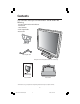
Contents Your new NEC AccuSync LCD monitor box* should contain the following: • AccuSync LCD monitor with tilt base • Power Cord • User’s Manual • Video Signal Cable • Base stand Power Cord Video Signal Cable AccuSync LCD monitor (base stand not connected) AccuSync LCD51V/LCD71V Base Stand User’s Manual * Remember to save your original box and packing material to transport or ship the monitor. 2 AS5171Vmanual073003.
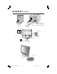
Quick Start To attach the Base to the LCD Stand: 1. Insert the front of the LCD Stand into the holes in the front of the Base. 2. Next, position the locking tabs on the back side of the LCD Stand with the holes on the Base. Lower the Stand until locking tabs are secure. Stand 1 Locking Tabs 2 Front Base Base To attach the AccuSync LCD monitor to your system, follow these instructions: 1. Turn off the power to your computer. 2.
Quick Start –continued Macintosh Cable Adapter (not included) Figure A.1 Figure A.2 Note: Some Macintosh systems do not require a Macintosh Cable Adapter Input (D-Sub) Figure B.1 Cable holder Power button Figure C.1 4 AS5171Vmanual073003.
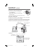
Quick Start –continued Tilt Grasp both sides of the monitor screen with your hands and adjust the tilt as desired (Figure TS.1). Figure TS.1 Remove Monitor Stand for Mounting To prepare the monitor for alternate mounting purposes: 1. Disconnect all cables. 2. Place monitor face down on a nonabrasive surface (Figure R.1). 3. Remove the 2 screws on the stand and lift off the stand (Figure R.1). 4. Remove the 4 screws connecting the monitor to the stand and remove the metal plate (Figure R.2).
Quick Start –continued Removing the Base Note: Always remove the Base when shipping the LCD. 1. Place monitor face down on a non-abrasive surface (Figure R.1). 2. While using your thumbs, press the bottom tabs upward to unlock. 3. Press the top tabs down to unlock and pull off the stand. Connecting a Flexible Arm This LCD monitor is designed for use with a flexible arm. Please use the attached screws (4pcs) as shown in the picture when installing.
Controls OSM® (On-Screen Manager) control buttons on the front of the monitor function as follows: 1.
Controls –continued BRIGHTNESS Adjusts the overall image and background screen brightness. CONTRAST Adjusts the image brightness in relation to the background. AUTO CONTRAST Adjusts the image displayed for non-standard video inputs. AUTO ADJUST Automatically adjusts the Image Position, the H. Size and Fine setting. LEFT/RIGHT Controls Horizontal Image Position within the display area of the LCD. DOWN/UP Controls Vertical Image Position within the display area of the LCD. H.
Controls –continued EXIT Selecting EXIT allows you exit OSM menu/sub menu. LANGUAGE OSM control menus are available in seven languages. OSM TURN OFF The OSM control menu will stay on as long as it is in use. In the OSM Turn OFF submenu, you can select how long the monitor waits after the last touch of a button to shut off the OSM control menu. The preset choices are 10 - 120 seconds in 5 second intervals.
Recommended Use Safety Precautions and Maintenance FOR OPTIMUM PERFORMANCE, PLEASE NOTE THE FOLLOWING WHEN SETTING UP AND USING THE ACCUSYNC LCD COLOR MONITOR: • DO NOT OPEN THE MONITOR. There are no user serviceable parts inside and opening or removing covers may expose you to dangerous shock hazards or other risks. Refer all servicing to qualified service personnel. • Do not spill any liquids into the cabinet or use your monitor near water.
Recommended Use –continued CORRECT PLACEMENT AND ADJUSTMENT OF THE MONITOR CAN REDUCE EYE, SHOULDER AND NECK FATIGUE. CHECK THE FOLLOWING WHEN YOU POSITION THE MONITOR: • For optimum performance, allow 20 minutes for warm-up. • Adjust the monitor height so that the top of the screen is at or slightly below eye level. Your eyes should look slightly downward when viewing the middle of the screen. • Position your monitor no closer than 16 inches and no further away than 28 inches from your eyes.
Specifications Monitor Specifications AccuSync LCD51V Monitor LCD Module Diagonal: Viewable Image Size: Native Resolution (Pixel Count): Input Signal Video: Sync: 15.0 inch 15.0 inch 1024 x 768 Active matrix; thin film transistor (TFT) liquid crystal display (LCD); 0.297 mm dot pitch; 250cd/m2 white luminence; 450:1 contrast ratio, typical ANALOG 0.
Specifications –continued Monitor Specifications AccuSync LCD71V Monitor LCD Module Diagonal: Viewable Image Size: Native Resolution (Pixel Count): Input Signal Video: Sync: 17.0 inch 17.0 inch 1280 x 1024 Active matrix; thin film transistor (TFT) liquid crystal display (LCD); 0.264 mm dot pitch; 250cd/m2 white luminence; 450:1 contrast ratio, typical ANALOG 0.
Features Reduced Footprint: Provides the ideal solution for environments requiring superior image quality but with size and weight limitations. The monitor’s small footprint and low weight allow it to be moved or transported easily from one location to another. AccuColor® Control Systems: Allows you to adjust the colors on your screen and customize the color accuracy of your monitor to a variety of standards.
Troubleshooting No • • • • picture The signal cable should be completely connected to the display card/computer. The display card should be completely seated in its slot. Front Power Switch and computer power switch should be in the ON position. Check to make sure that a supported mode has been selected on the display card or system being used. (Please consult display card or system manual to change graphics mode.
References NEC-Mitsubishi Monitor Customer Service & Support Customer Service and Technical Support: (800) 632-4662 Fax: (800) 695-3044 Parts and Accessories/Macintosh Cable Adapter: (888) NEC-MITS [888-632-6487] Customer Service Policies & Processes: http://www.necmitsubishi.com/ css/ServicePolicies/ServicePolicies.htm Online Technical Support Knowledge Base: http://www.necmitsubishi.com/ css/knowledgebase.cfm Customer Service & Technical Support Email: http://www.necmitsubishi.com/ css/techform.
Limited Warranty NEC-Mitsubishi Electronics Display of America, Inc. (hereinafter “NMD-A”) warrants this Product to be free from defects in material and workmanship and, subject to the conditions set forth below, agrees to repair or replace (at NMD-A’s sole option) any part of the enclosed unit which proves defective for a period of three (3) years from the date of first consumer purchase. Spare parts are warranted for ninety (90) days.
TCO’99 Congratulations! You have just purchased a TCO’99 approved and labelled product! Your choice has provided you with a product developed for professional use. Your purchase has also contributed to reducing the burden on the environment and also to the further development of environmentally adapted electronics products.
TCO’99 –continued accumulative* processes. Flame retardants have been found in human blood and researchers fear that disturbances in foetus development may occur. TCO’99 demand requires that plastic components weighing more than 25 grams must not contain flame retardants with organically bound chlorine and bromine. Flame retardants are allowed in the printed circuit boards since no substitutes are available. Lead** Lead can be found in picture tubes, display screens, solders and capacitors.
Declaration of the Manufacturer We hereby certify that the color monitor AccuSync™ LCD51V (L152R5) and AccuSync LCD71V (L172R6) are in compliance with Council Directive 73/23/EEC: – EN 60950 Council Directive 89/336/EEC: – EN 55022 – EN 61000-3-2 – EN 61000-3-3 – EN 55024 and marked with NEC-Mitsubishi Electric Visual Systems Corporation 4-13-23, Shibaura, Minato-Ku Tokyo 108-0023, Japan 20 AS5171Vmanual073003.
AVERTISSEMENT AFIN D’ÉVITER TOUT RISQUE D’INCENDIE OU D’ÉLECTROCUTION, NE PAS EXPOSER CET APPAREIL À LA PLUIE OU À L’HUMIDITÉ. NE PAS UTILISER LA FICHE D’ALIMENTATION POLARISÉE AVEC UNE PRISE DE CORDON DE RALLONGE OU AUTRE PRISE SAUF SI LES BROCHES PEUVENT ÊTRE ENTIÈREMENT INTRODUITES. NE PAS OUVRIR LE BOÎTIER, LEQUEL CONTIENT DES COMPOSANTS À HAUTE TENSION. CONFIER TOUS TRAVAUX À DU PERSONNEL TECHNIQUE QUALIFIÉ.
Contenu La boîte* de votre nouveau moniteur NEC AccuSync LCD contient : • • • • • Moniteur AccuSync LCD avec socle inclinable Cordon d'alimentation Manuel de l’utilisateur Support de base Câble pour le signal vidéo Cordon d'alimentation Câble pour le signal vidéo Moniteur AccuSync LCD (support et base non connectés) AccuSync LCD51V/LCD71V Support de base Manuel de l’utilisateur * Ne pas oublier de conserver la boîte et le matériel d'emballage d'origine pour transporter ou expédier le moniteur.
Mise en marche rapide Pour attacher la base au support LCD : 1. Insérez la partie avant du support LCD dans les trous à l’avant de la base. 2. Ensuite, alignez les languettes de verrouillage à l’arrière du stand LCD avec les trous de la base. Abaissez le support en place jusqu’à ce que les languettes de verrouillage soient maintenues en place. Support 1 Languettes de verrouillage 2 Trous à l’avant de la base Base Pour raccorder le moniteur AccuSync LCD au système,suivez les directives ciaprès: 1.
Mise en marche rapide (suite) Adaptateur Macintosh (non fourni) Figure A.1 Remarque: Certains systémes Macintosh ne nécessitent pas un adaptateur de câble Macintosh. Figure A.2 Input (D-Sub) Figure B.1 Étrier de câble Bouton d’alimentaion Figure C.1 24 AS5171Vmanual073003.
Mise en marche rapide (suite) Incliner Attrapez des deux mains l’écran du moniteur par les deux côtés et réglez l’inclinaison et l’orientation selon votre goût. (Figure TS.1) Figure TS.1 Enlever le support du moniteur pour le montage Pour préparer le moniteur à différents types de montage : 1. Déconnectez tous les câbles. 2. Placez le moniteur avec l’écran vers le bas sur une surface non abrasive (Figure R.1). 3. Enlever les 2 vis sur le support puis soulever ce dernier (Figure R.1). 4.
Mise en marche rapide (suite) Enlever la Base NOTA : Toujours enlever la base avant d’expédier le LCD. 1. Placer le moniteur partie avant en contact avec une surface non abrasive (Figure R.1). 2. À l’aide des pouces, appuyer sur les languettes inférieures en les poussant vers le bas pour déverrouiller. 3. Appuyer sur les languettes supérieures en les poussant vers le haut pour déverrouiller et tirer le support. Connexion d’un bras souple Ce moniteur LCD a été conçu pour être utilisé avec un bras flexible.
Commandes Les boutons de réglage OSM situés sur l’avant du moniteur fournissent les fonctions suivantes : 1.
Commandes (suite) LUMINOSITÉ Règle la luminosité de l'image générale et de l'écran d'arrière-plan. CONTRASTE Règle la luminosité de l'image par rapport à l'arrière-plan. RÉGLAGE AUTO Règle l’image affichée pour les modes vidéo non standard. RÉGLAGE AUTOMATIQUE Règle automatiquement la position, le format horizontal ou la résolution fine. GAUCHE/DROITET Contrôle la position horizontale de l’image dans la zone d’affichage du LCD.
Commandes (suite) EXTINCTION DE L’OSM Le menu de l’OSM restera actif aussi longtemps que vous l’utiliserez. Dans le menu d’extinction de l’OSM, vous pouvez choisir le temps que mettra l’affichage pour s’effacer après la dernière pression sur une touche. Les temps préréglés sont de 10-120 secondes. VERROUILLAGE OSM Cette commande permet de verrouiller l’accès à toutes les fonctions de contrôle OSM à l’exception des fonctions Sourdine, Son, Volume, Luminosité et Contraste.
Usage recommandé Consignes de sécurité et d’entretien POUR UN FONCTIONNEMENT OPTIMAL, PRIÈRE DE NOTER CE QUI SUIT POUR LE RÉGLAGE ET L'UTILISATION DU MONITEUR COULEUR MULTISYNC® LCD : • NE PAS OUVRIR LE MONITEUR. Aucune pièce intérieure ne nécessite l'intervention de l'utilisateur, et l'ouverture ou la dépose des couvercles peut entraîner des risques de décharges électriques dangereuses ou d'autres risques. Confier tous travaux à du personnel technique qualifié.
Usage recommandé (suite) LA MODIFICATION DE LA POSITION ET DU RÉGLAGE DU MONITEUR PEUT RÉDUIRE LA FATIGUE DES YEUX, DES ÉPAULES ET DE LA NUQUE. OBSERVER LES DIRECTIVES CI-APRÈS LORS DU POSITIONNEMENT DU MONITEUR : • Pour une performance optimale, laissez le moniteur se réchauffer pendant 20 minutes. • Régler la hauteur du moniteur de sorte que le dessus de l'écran soit au niveau ou légèrement en-dessous du niveau des yeux.
Fiche technique Caractér. techn. du moniteur Module LCD Moniteur AccuSync LCD51V Diagonale : Surface utile : Résolution (nombre de pixels) : Signal d'entrée Couleurs d'affichage Angles de visionnement maximal Gamme de synchronisation 15,0 po 15,0 po 1024 x 768 Vidéo : Sync : Matrice active; transistor à film fin (TFT); affichage à cristaux liquides (LCD); pas 0,297 mm; luminance blanche 250cd/m 2; taux de contraste caractéristique 450:1. ANALOGIQUE 0,7 Vp-p/75 Ohms Synchro séparée niveau TTL.
Fiche technique Caractér. techn. du moniteur Module LCD Moniteur AccuSync LCD71V Diagonale : Surface utile : Résolution (nombre de pixels) : Signal d'entrée Couleurs d'affichage Angles de visionnement maximal Gamme de synchronisation 17,0 po 17,0 po 1280 x 1024 Vidéo : Sync : Matrice active; transistor à film fin (TFT); affichage à cristaux liquides (LCD); pas 0,264 mm; luminance blanche 250cd/m 2; taux de contraste caractéristique 450:1. ANALOGIQUE 0,7 Vp-p/75 Ohms Synchro séparée niveau TTL.
Fonctions Encombrement réduit : Constitue la solution idéale pour les environnements qui nécessitent une image de haute qualité et un encombrement et un poids limités. L’encombrement réduit et le faible poids du moniteur permettent de le déplacer ou de le transporter rapidement d’un point à un autre. Système de commande AccuColor® : Permet de régler les couleurs à l’écran et de personnaliser la précision des couleurs selon diverses normes.
Dépannage Pas • • • d'image Le câble vidéo doit être bien connecté à la carte d'affichage et à l’ordinateur. La carte d'affichage doit être insérée à fond dans son logement. Les interrupteurs d’alimentation du moniteur à l’avantet de l’ordinateur doivent être sur la position MARCHE. • Vérifiez qu’un mode d’affichage autorisé a été sélectionné pour la carte d’affichage ou le système utilisé (veuillez consulter le manuel de votre carte d'affichage ou de votre système pour modifier le mode graphique).
Références Service à la clientèle et assistance technique du moniteur NEC-Mitsubishi Service à la clientèle et assistance technique: (800) 632-4662 Télécopieur: (800) 695-3044 Pièces et accessoires/adaptateur de câble Macintosh: Politiques et processus du service à la clientèle: Base de connaissance de l’assistance technique en lign: Adresse électronique du service à la clientèle et de l’assistance technique: (888) NEC-MITS [888-632-6487] http://www.necmitsubishi.com/ css/ServicePolicies/ServicePolicies.
Garantie limitée NEC-Mitsubishi Electronics Display of America, Inc. (ci-après «NMD-A») garantit que ce produit est exempt de vice de fabrication et de main-d’oeuvre et, selon les conditions énoncées ci-dessous, accepte de réparer ou remplacer, à sa discrétion, toute pièce de l’appareil concerné qui s’avérerait défectueuse et ce, pendant une période de trois (3) ans à partir de la date d’achat initial. Les pièces de rechange sont garanties pendant quatre-vingt dix (90) jours.
TCO’99 (C’est une traduction de portion Anglaise de TCO’99.) Félicitations! Vous avez acheté un produit qui répond à la directive TCO’99. En choisissant ce produit conçu pour une utilisation professionnelle, vous contribuez aussi à la réduction des effets nuisibles sur l’environnement et aussi au développement continu de produits électroniques respectueux de l’environnement.
TCO’99 (suite) organiquement liés. Les retardateurs de flame sont autorisés dans les cartes à circuits imprimés étant donné qu’aucun substitut n’est encore disponible. Plomb** Le plomb peut être présent dans les tubes cathodiques, les écrans, les soudures et les condensateurs. Le plomb s’attaque au système nerveux et, à doses élevées, entraîne l’intoxication par le plomb. La directive TCO’99 permet l’inclusion du plomb était donné qu’aucun remplacement n’ait encore été mis au point.
Déclaration du fabricant Nous certifions par la présente que les moniteurs AccuSync™ LCD51V (L152R5) au AccuSync LCD71V (L172R6) sont conformes à la directive 73/23/EEC du Counseil: – EN 60950 la directive 89/336/EEC du Counseil: – EN 55022 – EN 61000-3-2 – EN 61000-3-3 – EN 55024 et porte le sigle NEC-Mitsubishi Electric Visual Systems Corporation 4-13-23, Shibaura, Minato-Ku Tokyo 108-0023, Japan 40 AS5171Vmanual073003.
Série LCD NEC AVIS DE PROPRIÉTÉ EXCLUSIVE ET DE DÉGAGEMENT DE RESPONSABILITÉ Les informations contenues dans ce document, y compris tous les designs et matériel s'y rapportant, sont la propriété de NEC-Mitsubishi Electronics Display of America et/ou ses concédants.
NEC LCD Series PROPRIETARY NOTICE AND LIABILITY DISCLAIMER The information disclosed in this document, including all designs and related materials, is the valuable property of NECMitsubishi Electronics Display of America and/or its licensors, as appropriate, reserve all patent, copyright and other proprietary rights to this document, including all design, manufacturing, reproduction, use and sales rights thereto, except to the extent said rights are expressly granted to others.