
Electronics America Camera Lens User Manual


NEC Solutions (America), Inc.
Visual Systems
MT1055/1056 Installation Data
with Optional MT13ZL Short Focus Zoom Lens v 3.0
Page 2
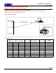
Projection Distance and Screen Size for Ceiling Mount
The following shows the proper relative position of the projector and screen. Refer to the table for installation data.
Distances are in inches. For millimeters multiply by 25.4.
Ceiling Mount Installation
C
α
Screen Ctr
Scrn Bottom
Screen Top
Lens Ctr
Throw Distance
A
C
I
N
@
`
1.7"
Lens Offset from
Mounting Pipe
D
B
9.3"
5.8"
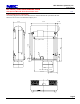
Distance Chart
BCD
α
Diagonal Width Height wide - tele wide - tele
40" 32" 24" 10.2" 39.3" - 48.8" 1.8" 14.6° - 11.8°
60" 48" 36" 15.3" 60.1" - 74.4" 2.7" 14.3° - 11.6°
67" 53.6" 40.2" 17.1" 67.3" - 83.4" 3.0" 14.3° - 11.6°
72" 57.6" 43.2" 18.4" 72.5" - 89.8" 3.2" 14.2° - 11.6°
84" 67.2" 50.4" 21.5" 85.0" - 105.1" 3.7" 14.2° - 11.5°
90" 72" 54" 23.0" 91.2" - 112.8" 4.0" 14.1° - 11.5°
100" 80" 60" 25.5" 101.6" - 125.6" 4.5" 14.1° - 11.5°
120" 96" 72" 30.6" 122.4" - 151.1" 5.4" 14.1° - 11.5°
150" 120" 90" 38.3" 153.6" - 189.5" 6.7" 14.0° - 11.4°
180" 144" 108" 46.0" 184.8" - 227.9" 8.0" 14.0° - 11.4°
Screen Size
Note: For screen sizes not indicated on the projection tables, use the formulas on page 1.