User’s Manual E705 E805 E905
Index Declaration of conformity............................................................................................................................... English-1 Important Information.................................................................................................................................... English-2 WARNING........................................................................................................................................ English-2 CAUTION..................
FCC Information 1. Use the attached specified cables with this display so as not to interfere with radio and television reception. (1) Please use the supplied power cord or equivalent to ensure FCC compliance. (2) Please use a good quality shielded video signal cable. Use of other cables and adapters may cause interference with radio and television reception. 2. This equipment has been tested and found to comply with the limits for a class A digital device, pursuant to Part 15 of the FCC Rules.
Important Information WARNING TO PREVENT FIRE OR SHOCK HAZARDS, DO NOT EXPOSE THIS UNIT TO RAIN OR MOISTURE. ALSO, DO NOT USE THIS UNIT’S POLARIZED PLUG WITH AN EXTENSION CORD RECEPTACLE OR OTHER OUTLETS UNLESS THE PRONGS CAN BE FULLY INSERTED. REFRAIN FROM OPENING THE CABINET AS THERE ARE HIGH VOLTAGE COMPONENTS INSIDE. REFER SERVICING TO QUALIFIED SERVICE PERSONNEL. CAUTION CAUTION: TO REDUCE THE RISK OF ELECTRIC SHOCK, MAKE SURE POWER CORD IS UNPLUGGED FROM WALL SOCKET.
• • • • • • • • FOR OPTIMUM PERFORMANCE, PLEASE NOTE THE FOLLOWING WHEN SETTING UP AND USING THE MULTI-FUNCTION MONITOR: DO NOT OPEN THE MONITOR. There are no user serviceable parts inside and opening or removing covers may expose you to dangerous shock hazards or other risks. Refer all servicing to qualified service personnel. Do not spill any liquids into the cabinet or use your monitor near water.
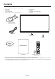
Contents Your new monitor box* should contain the following: • LCD monitor • Setup Manual • Power cord*1 • Clamp x 1 • Video Signal Cable • Screw with washer (M4 x 10) x 1 • Wireless Remote Control and AAA Batteries • CD-ROM Video Signal Cable (DVI-D to DVI-D cable) Power Cord*1 Screw with washer (M4 x 10) x 1 Clamp x 1 CD-ROM Setup Manual Setup Manual * Wireless Remote Control and AAA Batteries Remember to save your original box and packing material to transport or ship the monitor.
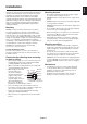
This device cannot be used or installed without the Tabletop Stand or other mounting accessory for support. For proper installation it is strongly recommended to use a trained, NEC authorized service person. Failure to follow NEC standard mounting procedures could result in damage to the equipment or injury to the user or installer. Product warranty does not cover damage caused by improper installation. Failure to follow these recommendations could result in voiding the warranty.
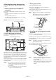
Attaching Mounting Accessories 3. Using Option Board The monitor is designed for use with the VESA mounting system. 1. Turn off the main power switch. 2. Remove the attached slot cover by unscrewing the installed screws (Figure 1). 1. Attach eyebolts (not included) for mounting 3. Insert option board in to the monitor. Attach the slot cover by using the removed screws. This model is equipped with attachable eyebolts to aid in mounting.
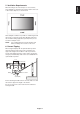
When mounting in an enclosed space or recessed area, leave adequate room between the monitor and the enclosure to allow heat to disperse, as shown below. Allow adequate ventilation or provide air conditioning around the monitor, so that heat can properly dissipate away from the unit and mounting apparatus; especially when you use monitors in multiple screen. NOTE: The sound quality of the internal speakers will differ according to the acoustics of the room. 6.
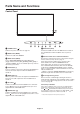
Parts Name and Functions Control Panel A POWER button ( H EXIT button (EXIT) ) Switches the power on/off. See also page 16. Activates the OSD menu when the OSD menu is turned-off. Acts as EXIT button within the OSD to move to previous menu. B MUTE button (MUTE) Switches the audio mute ON/OFF. I Remote control sensor and Power Indicator C INPUT button (INPUT) Acts as SET/POINT ZOOM button within OSD menu. (Toggle switches between [DVI], [DPORT], [HDMI], [VGA] or [Y/Pb/Pr], [HDMI2]).
English Terminal Panel A AC IN connector J VGA IN (mini D-Sub 15 pin) Connects with the supplied power cord. To input analog RGB signals from a personal computer or from other RGB equipment. This input can be used with an RGB or COMPONENT source. Please select signal type in TERMINAL SETTING. See page 27. NOTE: When you use this connector for COMPONENT, please use a suitable signal cable. If you have any questions, please ask your dealer. B Main Power Switch On/Off switch to turn main power ON/OFF.
Wireless Remote Control E AUDIO INPUT button Selects audio input source [IN1], [IN2], [OPTION]*2, [HDMI], [DPORT], [HDMI2]. F OPTION MENU button*1 G KEYPAD Press buttons to set and change passwords, change channel and set REMOTE ID. H ENT button*1 I DISPLAY button Turns on/off the information OSD. See page 18. J MENU button Turns on/off the menu mode. K AUTO SET UP button Enters auto setup menu. See page 20. L EXIT button Returns to previous menu within OSD menu.
Main picture Connector DPORT DVI HDMI VGA Y/Pb/Pr OPTION HDMI2 DisplayPort DVI-D HDMI D-Sub Option HDMI2 DPORT No Yes Yes Yes Yes Yes Yes DVI Yes No Yes Yes Yes Yes Yes HDMI Yes Yes No Yes Yes Yes Yes Sub picture VGA Y/Pb/Pr Yes Yes Yes Yes Yes Yes No No No No Yes Yes Yes Yes OPTION Yes Yes Yes Yes Yes No Yes Point the top of the remote control toward the LCD monitor’s remote sensor during button operation. Use the remote control within a distance of about 7 m (23 ft.
Setup 1. Determine the installation location NEC recommends the following battery use: CAUTION: Installing your LCD monitor must be done by a qualified technician. Contact your dealer for more information. • Place “AAA” size batteries matching the (+) and (-) signs on each battery to the (+) and (-) signs of the battery compartment. • Do not mix battery brands. • Do not combine new and old batteries. This can shorten battery life or cause liquid leakage of batteries.
When connected with a computer, switch on the power of the computer first. 6. Operate the attached external equipment Display the signal from the desired input source. 7. Adjust the sound Make volume adjustments when required. 8. Adjust the screen (See pages 20 and 21) Make adjustments of the screen display position when necessary. 9. Adjust the image (See page 20) Make adjustments such as backlight or contrast when required. 10.
Connections NOTE: Do not connect/disconnect cables when turning on the monitor or other external equipment as this may result in a loss of the monitor image. NOTE: Use an audio cable without a built-in resistor. Using an audio cable with a built-in resistor turns down the sound. Before making connections: * First turn off the power of all the attached equipment and make connections. * Refer to the user manual included with each separate piece of equipment.
Connecting your computer to your LCD monitor will enable you to display your computer’s screen image. Some video cards may not display an image correctly. Your LCD monitor displays proper image by adjusting the factory preset timing signal automatically. Resolution 640 x 480 800 x 600 1024 x 768 1280 x 768 1360 x 768 1280 x 1024 1600 x 1200 1920 x 1080 • Scanning frequency Horizontal Vertical 31.5 kHz 60 Hz 37.9 kHz 60 Hz 48.
Basic Operation Power ON and OFF Modes The LCD monitor power indicator will turn green while powered on and will turn red or amber while powered off. NOTE: The Main Power Switch must be in the ON position in order to power up the monitor using the remote control or the Power Button.
Picture Aspect Mode Power ON Power OFF and Power Save “AUTO POWER STANDBY” Power consumption under 0.5 W Power Save “AUTO POWER SAVE” Power consumption under 2.
Information OSD The Information OSD provides information such as: Input Source, Picture Size, etc. Press the DISPLAY button on the remote to bring up the Information OSD.
NOTE: English OSD (On-Screen-Display) Controls Some functions may not be available depending on the model or optional equipment. Input source Main Menu Icons Main Menu Item 70 50 50 50 50 50 Sub Menu PICTURE MODE Select Adjustment Settings THANK YOU FOR SAVING THE ENVIRONMENT. CARBON FOOTPRINT 86.0 % Goto Adjustment Return Close Key Guide Press UP or DOWN button to select sub-menu. Press SET/POINT ZOOM. Press UP or DOWN, PLUS or MINUS to select the function or setting to be adjusted.
Setting Default PICTURE BACKLIGHT Adjusts the overall image and background brightness. Press + or - to adjust. NOTE: When MODE1 or MODE2 is selected in ROOM LIGHT SENSING, this function cannot be changed. 70 CONTRAST Adjusts the image brightness in relationship to the input signal. Press + or - to adjust. NOTE: When sRGB is selected in picture mode, this function cannot be changed. 50 SHARPNESS Adjusts the crispness of the image. Press + or - to adjust.
Adjusts the visual “noise” on the image. - H RESOLUTION Adjusts the horizontal size of the image. - V RESOLUTION Adjusts the vertical size of the image. - INPUT RESOLUTION If there is a problem with signal detection, this function forces the monitor to display the signal at the desired resolution. After selection, execute “AUTO SETUP” if required. If no problem is detected, the only available option will be “AUTO”. AUTO ASPECT Select the aspect ratio of the screen image.
BASS To accentuate or reduce the low frequency sound. Press + button to increase BASS sound. Press - button to decrease BASS sound. SURROUND Artificial surround sound. NOTE: Audio out is disabled when this function is set to ON. PIP AUDIO Selects source of PIP audio. LINE OUT Selecting “VARIABLE” enables control of the line out level with the VOLUME button. NOTE: Audio out is disabled when this function is set to ON.
Sets the transparency of the Text Ticker (0: transparent, 100: opaque). DETECT Enables auto-detection of the Text Ticker. FADE IN Enables fade-in of the text ticker. RESET Resets PIP options back to factory settings except SUB INPUT and ASPECT. English BLEND - OSD LANGUAGE Select the language used by the OSD. ENGLISH ENGLISH (Depends on destination) DEUTSCH FRANÇAIS ITALIANO ESPAÑOL SVENSKA РУССКИЙ MENU DISPLAY TIME Turns off the OSD after a period of inactivity.
AUTO ID (not adjustable) - AUTO ID RESET - (not adjustable) IR LOCK SETTINGS MODE SELECT Prevents the monitor from being controlled by the wireless remote control. When ACTIVATE is selected, all the settings are activated. NOTE: IR LOCK SETTINGS is a function intended only to the wireless remote control buttons. This function does not lock out access to all buttons at the back of the monitor. To return to normal operation, press the “DISPLAY” button on the remote control for 5 seconds.
POWER SAVE Sets how long the monitor waits to go into power save mode after the signal is lost. NOTE: When connecting DVI, the video card might not stop sending the digital data even though the image might have disappeared. If this occurs the monitor will not switch into power management mode. AUTO STANDBY AUTO POWER SAVE The monitor automatically goes into OFF at the preset time period after signal is lost. The monitor will return to normal mode when signal is restarted.
SUBNET MASK: Set your subnet mask number of the network connected to the monitor when “MANUAL” is selected for [IP SETTING]. DEFAULT GATEWAY: Set your default gateway of the network connected to the monitor when “MANUAL” is selected for [IP SETTING]. NOTE: Set as [0.0.0.0] to delete the setting. 0.0.0.0 DNS Set for IP ADDRESS setting of DNS server. AUTO: Automatically assign an IP address of DNS server connected to the monitor. MANUAL: Set your IP address of DNS server connected to the monitor.
DVI-HD DVI MODE Selects the kind of DVI-D equipment which is connected to the DVI input. Select “DVI-HD” when DVD player or computer equipment, which requires HDCP authentication, is connected. Select “DVI-PC” when a computer equipment, which not requires HDCP authentication, is connected. D-SUB MODE Selects the type of signal associated with the D-SUB input.
120Hz (not adjustable) - TOUCH PANEL (not adjustable) Resets the following settings within the ADVANCED OPTION menu back to factory setting: INPUT DETECT (except the priority of input signals), INPUT CHANGE (except for INPUT1 and INPUT2), TERMINAL SETTING, DEINTERLACE, COLOR SYSTEM, OVER SCAN, AUDIO in OPTION SETTING. - Adjusts the backlight of the LCD automatically depending on the amount of ambient light. - AUTO BRIGHTNESS Adjusts the brightness level according to the input signal.
The schedule function allows the display to be set to power on and off at different times. Up to seven different schedules can be programmed. To program the schedule: 1. Enter the SCHEDULE menu. Highlight SCHEDULE SETTINGS using the up and down buttons. Press the SET/POINT ZOOM or the + button to enter the Settings menu. Highlight the desired schedule number and press SET/POINT ZOOM. The box next to the number will turn yellow. The schedule can now be programmed. 2.
Remote Control Function REMOTE CONTROL ID FUNCTION REMOTE CONTROL ID The remote control can be used to control up to 100 individual monitors using what is called the REMOTE CONTROL ID mode. The REMOTE CONTROL ID mode works in conjunction with the Monitor ID, allowing control of up to 100 individual monitors. For example: if there are many monitors being used in the same area, a remote control in normal mode would send signals to every monitor at the same time (see Figure 1).
This LCD monitor can be controlled by connecting a personal computer with a RS-232C terminal. Functions that can be controlled by a personal computer are: • Power ON or OFF. • Switching between input signals. • Sound Mute ON or OFF. Connection LCD Monitor + PC LCD Monitor PC RS-232C RS-232C Cable NOTE: If your PC is equipped only with a 25-pin serial port connector, a 25-pin serial port adapter is required. Contact your dealer for details.
2) Control command diagram For other commands, please see “External_Control.pdf” file on the CD-ROM.
Connecting to a Network Using a LAN cable allows you to specify the Network Settings and the Alert Mail Settings by using an HTTP server function. To use a LAN connection, you are required to assign an IP address. Example of LAN connection: Server NOTE: Use a category 5 or higher LAN cable. Hub LAN cable (not supplied) Network Setting by Using an HTTP Browser Overview Connecting the monitor to a network allows for monitor control from a computer via the network.
Preparation Before Use Connect the monitor to a commercially available LAN cable before engaging in browser operations. Operation with a browser that uses a proxy server may not be possible depending on the type of proxy server and the setting method. Although the type of proxy server will be a factor, it is possible that items that have actually been set will not be displayed depending on the effectiveness of the cache, and the contents set from the browser may not be reflected in operation.
English Network Setting Click “NETWORK” on the left side of HOME. IP SETTING Set for IP ADDRESS SETTING. AUTO: Automatically assign an IP address. MANUAL: Set your IP address of the network connected to the monitor. NOTE: Consult your network administrator for the IP address when [AUTO] is selected for [IP SETTING]. IP ADDRESS Set your IP address of the network connected to the monitor when [MANUAL] is selected for [IP SETTING].
Mail Setting Click “MAIL” on the left side of HOME. This option notifies your computer of an error message via e-mail when using wired LAN. An error message notification will be sent when an error occurs in the monitor. Alert Mail Checking [ENABLE] will turn on the Alert Mail feature. Checking [DISABLE] will turn off the Alert Mail feature. STATUS MESSAGE Checking [ENABLE] will turn on the STATUS MESSAGE feature. Checking [DISABLE] will turn off the STATUS MESSAGE feature.
Error number * ErrorCode 70h ~ 7Fh 80h ~ Fh 90h ~ 9Fh A0h ~ AFh Alert mail Message The monitor’s power supply is not functioning normally. The cooling fan has stopped. The monitor’s back light unit is not functioning normally. The monitor is overheated. A2h B0h ~ BFh E0h ~ EFh The monitor doesn’t have the input signal. The system error occurred in the monitor. Explanation Measure Standby power Abnormal Please contact your supplier.
SNMP Setting Click “SNMP” on the left side of HOME. This function allows for getting status and controlling of a monitor via the network. Version: SNMP v1 Authenticated plaintext by community name, not return a confirmation message of Trap. SNMP v2c Authenticated plaintext by community name, return a confirmation message of Trap. Community name: The default setting of community name is “public”. It is read only. You can set community names for up to 3 settings.
English AMX Setting Click “AMX” on the left side of HOME. AMX BEACON Turn on or off for detection from AMX Device Discovery when connecting to the network supported by AMX’s NetLinx control system. TIP: When using a device that supports AMX Device Discovery, all AMX NetLinx control system will recognize the device and download the appropriate Device Discovery Module from an AMX server. Checking [ENABLE] will detect the device from AMX Device Discovery.
Name Setting Click “NAME” on the left side of HOME. MONITOR NAME Set a monitor name. The name must be 16 characters or less. The default is model name. HOST NAME Type in the hostname of the network connected to the monitor. Up to 15 alphanumeric characters can be used. DOMAIN NAME Type in the domain name of the network connected to the monitor. Up to 60 alphanumeric characters can be used. Network Password Setting Click “NETWORK PASSWORD” on the left side of HOME.
English Memo Setting Click “MEMO” on the left side of HOME. Set a title and meesage. TITLE A title must be 24 characters or less. MESSAGE A message must be 240 characters or less. MEMO PASSWORD The default is “0000”. MEMO PASSWORD ENABLE MEMO PASSWORD is required when setting MEMO.
POINT ZOOM Using “SET/POINT ZOOM” button on a remote control allows to enlarge a partial of image. Press CH+/- button to zoom up or down. The image can be expanded from 1 to 10 times. 1 Press [SET/POINT ZOOM] button on a remote control. An icon will be a magnifier. 2 Move magnifier icon by [ ] [ ] [+] [-] button. 3 Press [CH+] to zoom up. Press [CH-] to zoom down. 4 Press [SET/POINT ZOOM] to disappear the icon. 5 Press [EXIT] to return to a normal size. 6 Press [MENU] to display OSD menu.
Reduced Footprint: Provides the ideal solution for environments with superior image quality. Color Control Systems: Allow you to adjust the colors on your screen and customize the color accuracy of your monitor to a variety of standards. OmniColor: Combines Six-axis color control and the sRGB standard. Six-axis color control permits color adjustments via six axes (R, G, B, C, M and Y) rather than through the three axes (R, G and B) previously available.
Troubleshooting No picture • The signal cable should be completely connected to the display card/computer. • Check the main Power Switch, it should be in the ON position. • Make certain the computer is not in a power-saving mode (touch the keyboard or mouse). • The display card should be completely seated in its slot. • • Check the main Power Switch, it should be in the ON position. Check to see that the power indicator option in the OSD is set to ON.
Product Specifications LCD Module 70”/1765.6 mm diagonal Resolution: 1920 x 1080 Color: Over 16 million colors (depending on video card used) Frequency Horizontal: 15.625/15.734 kHz, 31.5 kHz - 91.1 kHz (Analog Input) 31.5 kHz - 91.1 kHz (Digital Input) Vertical: 50.0 - 85.0 Hz Pixel Clock 25.2 MHz - 162.0 MHz Viewable Size 1538.9 x 865.
Specifications - E805 Product Specifications LCD Module 80”/2032.2 mm diagonal Resolution: 1920 x 1080 Color: Over 1073 million colors (depending on video card used) Frequency Horizontal: 15.625/15.734 kHz, 31.5 kHz - 91.1 kHz (Analog Input) 31.5 kHz - 91.1 kHz (Digital Input) Vertical: 50.0 - 85.0 Hz Pixel Clock 25.2 MHz - 162.0 MHz Viewable Size 1771.2 x 996.
Product Specifications LCD Module 90”/2286.6 mm diagonal Resolution: 1920 x 1080 Color: Over 1073 million colors (depending on video card used) Frequency Horizontal: 15.625/15.734/26.973 kHz, 31.5 kHz - 91.1 kHz (Analog Input) 15.625/15.734/26.973 kHz, 31.5 kHz - 91.1 kHz (Digital Input) Vertical: 24.0/30.0 Hz,50.0-85.0 Hz (Analog Input) 24.0 Hz,50.0-85.0 Hz (Digital Input) Pixel Clock 25.2 MHz–162.0 MHz (Analog Input) 25.0 MHz–162.0 MHz (DVI) (Digital Input) 25.0 MHz–300.
Pin Assignment 1) Analog multi input (MiniDsub15p): VGA, Y/Pb/Pr Pin No 1 2 3 4 5 6 7 8 9 10 11 12 13 14 15 Name Red, Y/Pb/Pr_Pr Green, Y/Pb/Pr_Y Blue, Y/Pb/Pr_Pb GND DDC-GND Red-GND Green-GND Blue-GND +5V (DDC) Mini D-SUB 15P (Monitor side) 1 5 6 10 11 15 GND NC DDC-SDA H-SYNC V-SYNC DDC-SCL 2) RS-232C input Pin No 1 2 3 4 5 6 7 8 9 Name NC RXD TXD NC GND NC NC NC NC D-SUB 9P (Monitor side) 5 1 6 9 This LCD monitor uses RXD, TXD and GND lines for RS-232C control.
NEC DISPLAY SOLUTIONS is strongly committed to environmental protection and sees recycling as one of the company’s top priorities in trying to minimize the burden placed on the environment. We are engaged in developing environmentally-friendly products, and always strive to help define and comply with the latest independent standards from agencies such as ISO (International Organisation for Standardization) and TCO (Swedish Trades Union).
For EU: The crossed-out wheeled bin implies that used batteries should not be put to the general household waste! There is a separate collection system for used batteries, to allow proper treatment and recycling in accordance with legislation. According the EU directive 2006/66/EC, the battery can’t be disposed improperly. The battery shall be separated to collect by local service.