User's Manual 1.
Index Warning .................................................................................................. 1 Contents ............................................................................................... 2 Quick Start ........................................................................................... 3 Controls ................................................................................................ 5 Recommended Use ............................................................
WARNING TO PREVENT FIRE OR SHOCK HAZARDS, DO NOT EXPOSE THIS UNIT TO RAIN OR MOISTURE. ALSO, DO NOT USE THIS UNIT'S POLARIZED PLUG WITH AN EXTENSION CORD RECEPTACLE OR OTHER OUTLETS UNLESS THE PRONGS CAN BE FULLY INSERTED. REFRAIN FROM OPENING THE CABINET AS THERE ARE HIGH VOLTAGE COMPONENTS INSIDE. REFER SERVICING TO QUALIFIED SERVICE PERSONNEL. CAUTION RISK OF ELECTRIC SHOCK • DO NOT OPEN CAUTION: TO REDUCE THE RISK OF ELECTRIC SHOCK, DO NOT REMOVE COVER (OR BACK). NO USER SERVICEABLE PARTS INSIDE.
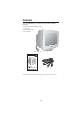
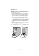
Contents Your new NEC MultiSync® FE monitor box* should contain the following: • • • • MultiSync FE Monitor with tilt/swivel base Power Cord Captive Signal Cable User’s Manual Captive Signal Cable MultiSync FE791SB /FE991SB ® TM Power Cord TM User’s Manual * Remember to save your original box and packing material to transport or ship the monitor.
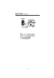
Quick Start To attach the FE monitor to your system, follow these instructions: 1. Turn off the power to your computer. 2. If necessary, install the display card into your system. For more information, refer to the display card manual. 3. For the PC: Connect the 15-pin mini D-SUB of the captive signal cable to the connector of the display card in your system (Figure A.1). Tighten all screws.
Quick Start –continued Figure C.1 Power Button Figure D.
Controls OSM™ (On-Screen Manager) control buttons on the front of the monitor function as follows: Main Menu Exits the OSM menu. EXIT Sub-Menu Exits to the OSM controls main menu. Moves the highlighted area left/right to select one of the controls. CONTROL / Moves the highlighted area left/right to select one of the sub-menus. CONTROL –/+ Has no function. Moves the bar in the – or + direction to decrease or increase the adjustment. SELECT/ SBMODE Enters sub-menu. Has no function.
Controls –continued Color Control/AccuColor® Control System Color presets selects the desired color setting. The bar is replaced by the color setting choice. Each color setting is adjusted at the factory to the stated Kelvin. If a setting is adjusted, the name of the setting will change from Kelvin to Custom except sRGB mode. Red, Green, Blue: AccuColor Control System decreases or increases the monitor's red, green or blue color guns depending upon which is selected.
Controls –continued • Use the CONVERGENCE (HOR.) control to adjust the alignment of the lines in the up/ down direction. • Use the CONVERGENCE (VER.) control to adjust the alignment of the lines in the left/right direction. Tools 2 Language: OSM controls menus are available in 6 languages. OSM Position: You can choose where you would like the OSM controls menu to appear on your screen.
Recommended Use Safety Precautions and Maintenance FOR OPTIMUM PERFORMANCE, PLEASE NOTE THE FOLLOWING WHEN SETTING UP AND USING THE MULTISYNC® FE COLOR MONITOR: • DO NOT OPEN THE MONITOR. There are no user serviceable parts inside and opening or removing covers may expose you to dangerous shock hazards or other risks. Refer all servicing to qualified service personnel. • Do not spill any liquids into the cabinet or use your monitor near water.
Recommended Use –continued CORRECT PLACEMENT AND ADJUSTMENT OF THE MONITOR CAN REDUCE EYE, SHOULDER AND NECK FATIGUE. CHECK THE FOLLOWING WHEN YOU POSITION THE MONITOR: • Adjust the monitor height so that the top of the screen is at or slightly below eye level. Your eyes should look slightly downward when viewing the middle of the screen. • Position your monitor no closer than 16 inches and no further away than 24 inches from your eyes. The optimal distance is 20 inches.
Specifications Monitor Specifications Picture Tube Diagonal: Viewable Image Size: Radius: Input Signal Video: Sync: Display Colors Synchronization Range Analog input: Horizontal: Vertical: Resolutions Supported Resolution based on horizontal and vertical frequencies only Active Display Area (Factory Setting) Horizontal: Vertical: Active Display Area (Full Scan) MultiSync® FE791SB Monitor Notes 17 inch 16 inch 50,000 mm 90° deflection, 0.
Specifications –continued Monitor Specifications Picture Tube Diagonal: Viewable Image Size: Radius: Input Signal Video: Sync: Display Colors Synchronization Range Analog input: Horizontal: Vertical: Resolutions Supported Resolution based on horizontal and vertical frequencies only Active Display Area (Factory Setting) Horizontal: Vertical: Active Display Area (Full Scan) MultiSync® FE991SB Monitor Notes 19 inch 18 inch 50,000 mm 90° deflection, 0.25/0.
Features SuperBrightTM Diamondtron® CRT : This patented flat aperture grille CRT delivers an exceptional viewing experience with unprecedented brightness and contrast and a virtually flat image that reduces distortion and glare so that what you see on-screen is what you get on your printed output. The state-of-the-art Mitsubishi PX-DBFTM electron gun and tight 0.25mm grille pitch delivers precise focus for crisp, clear text and images.
Features –continued Reduced Magnetic Field™ Technology: Reduces magnetic and alternating electric field emissions and static electricity, addressing ergonomic concerns regarding potential risks from extended computer monitor use. Multiple Frequency Technology: Automatically adjusts monitor to the display card’s scanning frequency, thus displaying the resolution required. FullScan™ Capability: Allows you to use the entire screen area in most resolutions, significantly expanding image size.
Troubleshooting No picture • • • • Display card should be completely seated in its slot. Power Button and computer power switch should be in the ON position. Signal cable should be completely connected to display card/computer. Check connector for bent or pushed-in pins. Image is scrolling or unstable • Signal cable should be completely attached to the computer. • Check pin assignments and signal timings of the monitor and your display card with respect to recommended timings and pin assignments.
References • BBS (978) 742-8706 NEC-Mitsubishi Electronics Display of America Remote Bulletin Board System is an electronic service accessible with your system and a modem. Communication parameters are: 300/1200/2400/9600/14.4k/28.8k/33.
Limited Warranty NEC-Mitsubishi Electronics Display of America, Inc. (hereinafter “NMD-A”) warrants this Product to be free from defects in material and workmanship and, subject to the conditions set forth below, agrees to repair or replace (at NMD-A’s sole option) any part of the enclosed unit which proves defective for a period of three (3) years from the date of first consumer purchase. Spare parts are warranted for ninety (90) days.
TCO’95 MultiSync® FE Black Model Congratulations! You have just purchased a TCO’95 approved and labeled product! Your choice has provided you with a product developed for professional use. Your purchase has also contributed to reducing the burden on the environment and also, to the further development of environmentally adapted electronics products.
TCO’95 –continued toxins, PCBs, which are suspected to give rise to similar harm, including reproductive damage in fisheating birds and mammals, due to the bio-accumulative* processes. Flame retardants have been found in human blood and researchers fear that disturbances in foetus development may occur. TCO’95 demand requires that plastic components weighing more than 25 grams must not contain organically bound chlorine and bromine.
TCO’99 MultiSync® FE White Model Congratulations! You have just purchased a TCO’99 approved and labeled product! Your choice has provided you with a product developed for professional use. Your purchase has also contributed to reducing the burden on the environment and also to the further development of environmentally adapted electronics products.
TCO’99 –continued health effects, including reproductive damage in fisheating birds and mammals, due to the bioaccumulative* processes. Flame retardants have been found in human blood and researchers fear that disturbances in foetus development may occur. TCO’99 demand requires that plastic components weighing more than 25 grams must not contain flame retardants with organically bound chlorine and bromine. Flame retardants are allowed in the printed circuit boards since no substitutes are available.
Declaration of the Manufacturer We hereby certify that the color monitor MultiSync® FE is in compliance with Council Directive 73/23/EEC: – EN 60950 Council Directive 89/336/EEC: EN 55022 – EN 61000-3-2 – EN 61000-3-3 – EN 55024 and marked with NEC-Mitsubishi Electric Visual Systems Corporation 686-1, Nishioi Oi-Machi Ashigarakami-gun Kanagawa 258-8533, Japan 21 1-23
NEC Flat Enterprises Series PROPRIETARY NOTICE AND LIABILITY DISCLAIMER The information disclosed in this document, including all designs and related materials, is the valuable property of NEC-Mitsubishi Electronics Display of America and/or its licensors, as appropriate, reserve all patent, copyright and other proprietary rights to this document, including all design, manufacturing, reproduction, use and sales rights thereto, except to the extent said rights are expressly granted to others.
2.
Declaration of the Manufacturer We hereby certify that the colour monitor MultiSync FE791SB / FE991SB is in compliance with Council Directive 73/23/EEC: – EN 60950 Council Directive 89/336/EEC: EN 55022 – EN 61000-3-2 – EN 61000-3-3 – EN 55024 and marked with NEC-Mitsubishi Electric Visual Systems Corporation 686-1, Nishioi Oi-Machi Ashigarakami-gun Kanagawa 258-8533, Japan ENERGYSTAR Product As an ENERGYSTAR Partner, NEC-Mitsubishi Electronics Display of America, Inc.
WARNING TO PREVENT FIRE OR SHOCK HAZARDS, DO NOT EXPOSE THIS UNIT TO RAIN OR MOISTURE. ALSO, DO NOT USE THIS UNIT'S POLARIZED PLUG WITH AN EXTENSION CORD RECEPTACLE OR OTHER OUTLETS UNLESS THE PRONGS CAN BE FULLY INSERTED. EFRAIN FROM OPENING THE CABINET AS THERE ARE HIGH VOLTAGE COMPONENTS INSIDE. REFER SERVICING TO QUALIFIED SERVICE PERSONNEL. CAUTION RISK OF ELECTRIC SHOCK • DO NOT OPEN CAUTION: TO REDUCE THE RISK OF ELECTRIC SHOCK, DO NOT REMOVE COVER (OR BACK). NO USER SERVICEABLE PARTS INSIDE.
Contents Your new MultiSync FE monitor box* should contain the following: • MultiSync FE Monitor with tilt/swivel base • Power Cord • Captive Signal Cable • User’s Manual • CD ROM with Setup Software, complete User’s Manual and other helpful files. To see the User’s Manual, Acrobat Reader 4.0 must be installed on your PC. Power Cord Captive Signal Cable User’s Manual Sales Office List CD-ROM * Remember to save your original box and packing material to transport or ship the monitor.
Quick Start To attach the MultiSync FE monitor to your system, follow these instructions: 1. Turn off the power to your computer. 2. If necessary, install the display card into your system. For more information, refer to the display card manual. 3. For the PC: Connect the 15-pin mini D-SUB of the captive signal cable to the connector of the display card in your system (Figure A.1). Tighten all screws.
Quick Start – continued Power Outlet Power Cord Figure C.1 Power Button Figure D.
Controls OSM (On-Screen Manager) control buttons on the front of the monitor function as follows: Main Menu Sub-Menu EXIT Exits the OSM menu. Exits to the OSM controls main menu. CONTROL Moves the highlighted area left/right to select one of the sub-menus. Moves the highlighted area left/right to select one of the controls. CONTROL –/+ Has no function. Moves the bar in the – or + direction to decrease or increase the adjustment.
Controls – continued Color Control System Colour presets selects the desired colour setting. The bar is replaced by the colour setting choice. Each colour setting is adjusted at the factory to the stated Kelvin. If a setting is adjusted, the name of the setting will change from Kelvin to Custom except sRGB mode. Red, Green, Blue: Color Control System decreases or increases the monitor's red, green or blue colour guns depending upon which is selected.
Controls – continued Tools 2 Language: OSM controls menus are available in 6 languages. OSM Position: You can choose where you would like the OSM controls menu to appear on your screen. Selecting OSM Position allows you to manually adjust the OSM controls menu position from among Center, Top left, Top right, Bottom left and Bottom right. OSM Turn Off: The OSM controls menu will stay on as long as it is in use.
Recommended Use Safety Precautions and Maintenance FOR OPTIMUM PERFORMANCE, PLEASE NOTE THE FOLLOWING WHEN SETTING UP AND USING THE MULTISYNC FE COLOUR MONITOR: • DO NOT OPEN THE MONITOR. There are no user serviceable parts inside and opening or removing covers may expose you to dangerous shock hazards or other risks. Refer all servicing to qualified service personnel. • Do not spill any liquids into the cabinet or use your monitor near water.
Recommended Use – continued CORRECT PLACEMENT AND ADJUSTMENT OF THE MONITOR CAN REDUCE EYE, SHOULDER AND NECK FATIGUE. CHECK THE FOLLOWING WHEN YOU POSITION THE MONITOR: • Adjust the monitor height so that the top of the screen is at or slightly below eye level. Your eyes should look slightly downward when viewing the middle of the screen. • Position your monitor no closer than 40 cm and no further away than 60 cm from your eyes. The optimal distance is 50 cm.
Specifications MultiSync FE791SB Monitor Monitor Specifications Picture Tube Diagonal: 43 cm/17 inch Viewable Image Size: 406 mm/16 inch Input Signal Notes 90° deflection, 0.25 mm grille pitch, medium short persistence phosphor, aperture grille CRT, multi-layered, antistatic screen coating, dark-tint screen and OptiClear screen. Video: ANALOG 0.7 Vp-p/75 Ohms Sync: Separate sync. TTL Level Horizontal sync. Positive/Negative Vertical sync. Positive/Negative Composite sync.
Specifications – continued MultiSync FE991SB Monitor Monitor Specifications Picture Tube Diagonal: 50 cm/19 inch Viewable Image Size: 457 mm/18 inch Input Signal Notes 90° deflection, 0.25/0.27 mm grille pitch, medium short persistence phosphor, aperture grille CRT, multilayered, anti-static screen coating, dark-tint screen and OptiClear screen. Video: ANALOG 0.7 Vp-p/75 Ohms Sync: Separate sync. TTL Level Horizontal sync. Positive/Negative Vertical sync. Positive/Negative Composite sync.
Features SuperBright Diamondtron CRT: This patented flat aperture grille CRT delivers an exceptional viewing experience with unprecedented brightness and contrast and a virtually flat image that reduces distortion and glare so that what you see on-screen is what you get on your printed output. The state-of-the-art Mitsubishi PX-DBF electron gun and tight 0.25 mm grille pitch delivers precise focus for crisp, clear text and images.
Troubleshooting No picture • • • • Display card should be completely seated in its slot. Power Button and computer power switch should be in the ON position. Signal cable should be completely connected to display card/computer. Check connector for bent or pushed-in pins. Image is scrolling or unstable • Signal cable should be completely attached to the computer. • Check pin assignments and signal timings of the monitor and your display card with respect to recommended timings and pin assignments.
TCO’99 MultiSync FE791SB / FE991SB Congratulations! You have just purchased a TCO’99 approved and labeled product! Your choice has provided you with a product developed for professional use. Your purchase has also contributed to reducing the burden on the environment and also to the further development of environmentally adapted electronics products.
TCO’99 – continued TCO’99 demand requires that plastic components weighing more than 25 grams must not contain flame retardants with organically bound chlorine and bromine. Flame retardants are allowed in the printed circuit boards since no substitutes are available. Lead** Lead can be found in picture tubes, display screens, solders and capacitors. Lead damages the nervous system and in higher doses, causes lead poisoning.