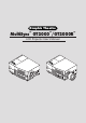
Graphic Theatre MultiSync™ GT2000™/GT2000R™ LCD Projector User’s Manual N O N O FF S TU R M S O ZO R TU TA E W S E TA S W O P /O FF O P /O M O ZO S U C FO R TE N R TE N E E S U C FO U N E M T C LE E S - U N E M T C LE E S - + + IN AC IN AC
IMPORTANT INFORMATION Precautions Important Safeguards Please read this manual carefully before using your NEC MultiSync GT2000/GT2000R LCD Projector and keep the manual handy for future reference. These safety instructions are to ensure the long life of your LCD projector and to prevent fire and shock. Please read them carefully and heed all warnings. Your serial number is located under the name plate label on the right side of your MultiSync GT2000/GT2000R . Record it here: Installation 1.
Cleaning 1. Unplug the LCD projector before cleaning. 2. Clean the cabinet periodically with a damp cloth. If heavily soiled, use a mild detergent. Never use strong detergents or solvents such as alcohol or thinner. 3. Use a blower or lens paper to clean the lens, and be careful not to scratch or mar the lens. 4. Clean the air filter with a vacuum cleaner after every 100 hours of operation. a. Clean the outside of the filter with a vacuum cleaner. b.
DOC avis de conformation ATTENTION DOC avis de conformation RISQUE D’ELECTROCUTION NE PAS OUVRIR Cet appareil numérique de la classe A respecte toutes les exigences du Règlement sur le Matériel Brouilleur du Canada. ATTENTION Importantes précautions de sécurité Pour couper l'alimentation principale, s'assurer de retirer la fiche de la prise de courant. La prise de courant murale doit être installée le plus près possible de l'équipement, et doit être facilement accessible.
Nettoyage 1. Débrancher le projecteur à écran à cristaux liquides (LCD) de la prise d’alimentation avant le nettoyage. 2. Nettoyer régulièrement le coffret avec un chiffon doux. S’il y a des taches tenaces, utiliser une solution d’un détergent doux. Ne jamais utiliser de détergents puissants ou des solvants, tel que l’alcool ou un diluant pour nettoyer le projecteur à écran à cristaux liquides (LCD). 3.
LIMITED WARRANTY (USA AND CANADA ONLY) ® NEC MultiSync LCD Projector Products NEC Technologies, Inc. (hereafter NECTECH) warrants this product to be free from defects in material and workmanship under the following terms. 1. Removal or installation charges. 2. Costs of initial technical adjustments (set-up), including adjustment of user controls. These costs are the responsibility of the NECTECH dealer from whom the product was purchased.
TABLE OF CONTENTS 1. Introduction What’s In The Box? ...................................................................................................... E-8 Getting To Know Your MultiSync GT2000/GT2000R LCD Projector .......................... E-9 Projector Cabinet ................................................................................................... E-9 Top Features ........................................................................................................
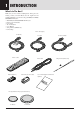
1 INTRODUCTION What’s In The Box? Make sure your box contains everything listed. If any pieces are missing, contact your dealer. Please save the original box and packing materials if you ever need to ship your MultiSync GT2000/ GT2000R LCD Projector.
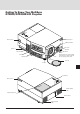
Getting To Know Your MultiSync GT2000/GT2000R LCD Projector O N S T P AT O U W S E R /O FF ZO O M - FO C U S E N TE R + + U E N M T S E LE C - + Remote Sensor Remote Sensor Main Power Switch Rear Foot AC One-Touch Tilt button IN Tilt Foot Filter Cover AC Input Plug the female end of the supplied power cable here, and the male end into a properly grounded outlet.
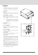
Top Features 1 Power Button Use this button to turn the power on and off when the Main Power Switch is on and the LCD projector is in standby. To turn off the projector, press and hold this button for at least 2 seconds. M Select: After you press the “Menu” button, use the ▲ or ▼ button to select the menu item you wish to adjust. (+)(–): Use these buttons while you' re in the adjustment mode to change the level of a selected menu item. These buttons are also used to set an item in the other menus.
Terminal Panel Features This panel is located on the left side and is where you connect your cables. 1 1 R/Cr, G/Y, B/Cb, H/ HV and V [RGB 1] Inputs (BNC) Connect R,G,B,H (Horizontal sync) and V (Vertical sync) outputs of external equipment such as the NEC ISS-6020 Switcher or IPS-4000. R/Cr NOTE: S-Video provides more vivid color and higher resolution than the traditional composite video format.
9 Remote Input Mini Jack Connect your remote control cable here for wired operation. 9 S-VIDEO INPUT AUDIO L/MONO R Remote Output Mini Jack This terminal enables you to loop up to 64 projectors with the same remote control operation. RGB 2 AUDIO RGB 1 AUDIO L/MONO R REMOTE 2/PC REMOTE INPUT REMOTE OUTPUT AUDIO OUTPUT REMOTE 1 EXT-CTL 12 13 14 L/MONO R VIDEO INPUT AUDIO 10 Video Input (RCA) Connect a VCR, DVD player, laser disc player, or document camera here to project video.
Remote Control Features You can use your remote control with the cable or wireless to operate your MultiSync GT2000/GT2000R LCD Projector. If you want to use your remote control with the cable, connect one end of the cable to the jack on the remote control and the other end to the Terminal Panel. OFF POWER ON 1 MENU 1 Power ON and OFF 2 4 If your main power switch on the front is turned on, you can use this button to turn your projector on and off.
10 Contrast Adjusts the image' s contrast for room conditions. 11 Brightness Adjusts the image' s brightness for room conditions. OFF POWER ON 12 Setup MENU Press this button and then press the ENTER button to return to the factory preset. Also you can search the memory by pressing the SETUP button and then the LOAD button. - 13 Normal This button returns the brightness, contrast or white balance RGB1 + ENTER RGB2 VIDEO/S-VIDEO to its factory default settings.
19 Zoom (Magnify/Reduce with CTL) Press the (W) or (T) button to zoom in or zoom out. (These buttons are not available on GT2000R.) Use these buttons with the CTL button to adjust the image Adr. SETUP NORMAL DISPLAY size. MUTE PICTURE AUDIO EXPAND 20 CTL(Control) FOCUS This button is pressed simultaneously with others (FOCUS, ZOOM, VOLUME, RGB1, RGB2, KEYSTONE, MAGNIFY, REDUCE, Adr. and direct selection of RGB and YCbCr) to ZOOM + W 19 operate functions.
You cannot operate the projector using the remote control if: • the remote ID is not set to [00]. • the remote ID is not the same as the projector ID. See page E-43 for setting remote ID and page E-38 for setting projector ID. Remote Control Notes • Use the remote control within a distance of about 7m (23feet) and at an angle of 30˚ above, below, to the left and to the right of the remote control sensor located at the front of the main unit.
2 INSTALLATION This section describes how to set up your MultiSync GT2000/ GT2000R LCD projector and how to connect video and audio sources. Setting Up Your MultiSync GT2000/ GT2000R LCD Projector Attaching the lens cap to the lens hood with the supplied string and rivet. (GT2000 only) Your MultiSync GT2000/GT2000R LCD Projector is simple to set up and use. But before you get started, you must first: 1. Determine the image size 2.
Using A Tabletop Or Cart (A) Top view 1. Place your LCD projector on a flat level surface at the optimal distance from the screen or wall so you realize the size image you want. (Avoid having bright room lighting or sun light directly on the screen or wall where you'll be projecting the image.) 2. Connect the power cable, remove the lens cap and turn the projector on. (If no input signal is available, the projector will display a background image.) 3. Ensure that the projector is centered to the screen.
Distance Chart (GT2000) Projection Distance and Image Size Diagonal Screen Size (inch) 300 240 200 160 120 100 80 60 40 20 0 1 2 3 4 5 6 7 8 9 10 11 12 13 im j Throw Distance C A α E D (m) 6 5 4 Center of WIDE 3 2 1 Center of TELE (8.9˚-8.6˚) (6.8˚-6.
Standard Zoom Lens (Wide) α β (sin= α) γ (cos= α) Degree 9.0 0.16 0.99 Screen Size H–Width 4 : 3 Diagonal inch mm inch mm 32 812.8 40 1016 mm inch mm inch mm inch mm inch 1557 61.3 1537 60.5 -32 -1.2 336 13.2 A C D E 8.9 0.15 0.99 8.8 0.15 0.99 8.8 0.15 0.99 8.8 0.15 0.99 48 56 64 72 1219.2 1422.4 1625.6 1828.8 60 70 80 90 1524 1778 2032 2286 2377 93.6 2349 92.5 -1 -0.0 458 18.0 2787 109.7 2754 108.4 14 0.6 519 20.4 3197 125.9 3160 124.4 29 1.1 580 22.9 3608 142.0 3566 140.4 44 1.7 641 25.
WARNING • • • • Only use your LCD projector on a solid, level surface. If the projector falls to the ground, you can be injured and the projector severely damaged. Do not use the LCD projector where temperatures vary greatly. The projector must be used at temperatures between 0˚C and 40˚C. Do not expose the LCD projector to moisture, dust, or smoke. This will degrade image performance. Ensure that you have adequate ventilation around your LCD projector so that heat can dissipate.
Standard Zoom Lens (Wide) α β (sin= α) γ (cos= α) Degree 9.0 0.16 0.99 Screen Size H–Width 4 : 3 Diagonal inch mm inch mm 32 812.8 40 1016 mm inch mm inch mm inch mm inch 1557 61.3 329 13.0 1537 60.5 -25 -1.0 A B C F 8.9 0.15 0.99 8.8 0.15 0.99 8.8 0.15 0.99 8.8 0.15 0.99 48 56 64 72 1219.2 1422.4 1625.6 1828.8 60 70 80 90 1524 1778 2032 2286 2377 93.6 451 17.8 2349 92.5 6 0.2 2787 109.7 512 20.2 2754 108.4 21 0.8 3197 125.9 573 22.6 3160 124.4 36 1.4 3608 142.0 634 25.0 3566 140.4 51 2.
GT2000R If your projector is mounted on the ceiling and your image is upside down, use the “Menu” and “Select” buttons on your projector cabinet or (▲) (▼) buttons on your remote control to correct the orientation. (See page E-39.) Reflecting The Image Rear Screen Projection Using a mirror to reflect your LCD projector's image enables you to enjoy a much larger image. Contact your NEC dealer if you need a mirror.
GT2000R C Screen center line GT2000R E Desktop line D Screen Bottom (m) 4 3 2 1 0 1 2 3 4 0 1 2 3 4 5 6 7 8 (m) Degree α β (sin= α) γ (cos= α) 0.0 0.0 1.0 Screen Size H–Width 4 : 3 Diagonal inch mm inch mm 32 812.8 40 1016 A (=C) mm inch mm inch mm inch 833 32.8 221 8.7 84 3.3 D E 72 48 64 56 1219.2 1422.4 1625.6 1828.8 90 80 60 70 2286 1524 2032 1778 1303 51.3 373 14.7 84 3.3 1539 60.6 449 17.7 84 3.3 1774 69.8 525 20.7 84 3.3 2009 79.1 602 23.7 84 3.
3 CONNECTIONS Wiring Diagram Connecting Your PC Or Macintosh Computer Connecting your PC or Macintosh computer to your GT2000/ GT2000R Projector will enable you to project your computer's screen image for an impressive presentation. IPS-4000/ IPS4000Q R/Cr G/Y B/Cb H/HV RGB INPUT 2 DVD Player or LaserDisc Player V RGB OUTPUT To connect to a PC or Macintosh, simply: 1. Turn off the power to your projector and computer. 2.
PC Control Interface An RS-232C cable enables you to use your PC as a controller for your projector. * * * * * * RS-232C (Straight cable) Baud rate: ................................ 9600 bps Data length: ............................. 8 bits Parity: ...................................... Odd parity Stop bit: ................................... 1 bit Communications procedure: ...
Command Communications Sequence When a command sent from the personal computer has been correctly received by the projector, an "ACK" is returned for the command. When the command has not been received correctly, a "Receive Error" is sent back. An invalid command will cause a "Command Error". Note: When an"ACK" from the projector is not confirmed and the next command is received by the projector, an error in communication can result.
Connections with the ISS-6020 Connections with One ISS-6020 Switcher Connecting your GT2000/GT2000R projector to a single ISS-6020 switcher (using a cable available separately) delivers a series of benefits: • You can handle input from ten sources simultaneously. • The ISS-6020 can be controlled by the remote provided with your GT2000/GT2000R or with the buttons on the projector cabinet. (Source selection without the use of a CTL-6010 cable must be performed with the GT2000 hand held remote control.
Connections with Multiple ISS-6020 Switcher You can accommodate as many as 100 sources by connecting your GT2000/GT2000R to one ISS-6020 switcher that acts as "master" and ten more switchers that are "slaves." To connect several ISS-6020s, the "Switcher Control" on the "Settings Menu" should be set to "SW 2 Level" for multiple projectors. (See page E-38.) Note: The more ISS-6020 switchers that are connected, the more time is needed for the projector to start up.
Connecting Multiple Projectors As many as 64 projectors can be connected together and controlled by the same PC. For more information about managing multiple projectors. See page E-31. External equipment (Max.
Operating Multiple Projector with Remote Control You can operate as many as 64 projectors with the same remote control in wireless operation. To do so: 1. Select [Settings Menu]→[Projector ID] under the main menu and assign an ID number to each projector. 2. Specify the remote ID number to the projector to be used. To do, press and hold the CTL and press Adr button to enter the ID number. You can operate the projector assigned the same ID number as the remote address.
External Control To turn your projector on and off, to turn the mute on or off and to switch video sources, use the EXT-CTL connector. * When using the external control, do the following: 1. Select the [Settings Menu]→[Ext.Control] under the main menu and select "On". 2. Set the pin 8 of the DIP switch (S8601) to "SHORT". The DIP switch is located inside the ISS-6020 system control module.
Setting The Data When the EX PW pin is low, the power is on; when high, the power is off. When the EX MT pin is low, Picture Mute is on; when high, Picture Mute is off. Power EX PW Picture Mute EX MT ON Low ON Lo OFF High OFF Hi Note: Channel settings are only valid when the ISS-6020 is connected. Note: If a channel is switched to another using the remote control when the external control is valid, the channel is forced to switch to the one set by the external control.
4 OPERATION General Controls Getting started This section describes the basic operation of the projector. The operation may differ depending on the makeup of the projector system; therefore, please follow the directions of your system administrator. Operation using the remote control is described here.
5. Adjust the Screen Size and then Adjust the Focus When the projector is set up permanently, there is no need to make the usual adjustments. (The Zoom and Focus buttons do not function on GT2000R.) A)Press the ZOOM W/T button and adjust the screen size. B) Press the FOCUS +/- button and adjust the focus. FOCUS 8. Switch Off the Main Power Press the "0" side of the POWER switch located on the front of the main unit. ZOOM + B) Press the POWER button for at least 2 seconds.
SETUP (Various Settings) Please make settings in conjunction with both the projector and the system. NOTE: To accommodate worldwide use of the projector, the default language setting for the projector is English. See below for the detailed setting procedure. Descriptions given here assume that the language setting of the unit has already been set to English. Default Settings of the Settings Menu The unit is set as described below before it is shipped from the factory. Please set any required items.
Selecting the Background Color When There Is No Signal [Background] This is the setting of the background color when there is no input signal. 1. Select [Settings Menu] → [Background] from the main menu. 2. Press the cursor ▲/▼ button and select the background color, then press the ENTER button to set. Blue...The background color will be blue. Black...The background color will be black.
Selecting the Switcher Control Method [Switcher Control] The switcher is a unit that switches the input equipment when a number of different video devices or computers are connected. When the REMOTE 1 connector is used, input selection and adjustment are permitted by the projector. See "Using User Memory and Channel Memory" on Page E-56. See "(Connections with the ISS-6020)" on Page E-28 for information about connections. 1. Select [Settings Menu] → [Switcher Control] from the main menu. 2.
Sync Signal Termination Setting [Sync Termination] This sets the impedance of the RGB/YCbCr Input 1 connector. This function sets whether or not the unit will accommodate a 75 ohm output (specification) impedance of the video or personal computer equipment. 1. Select [Settings Menu] → [Sync Termination] from the main menu. 2. Press the cursor ▲/▼ button and select the termination resistance value, then press the ENTER button to set. 75 ohms ...........................
Selecting Correction and Storage of Keystone Distortion [Keystone] Keystone distortion arises when the angles are off between the projector and screen in the vertical orientation at the time of setting up the projector. The keystone function is used in this distortion adjustment. When the setting is permanent, setting the keystone save function to On will enable projection using this adjustment value from the next occasion. • Adjusting Keystone Adjustment [Keystone] 1.
Adjustments and Settings with the Remote Control Buttons (Direct Operation) Functions can be called directly using the remote control buttons to make adjustments and settings (without the use of the on-screen menu display). Adjustment of the Picture • Returning to Standard Adjustments Contrast and brightness will return to the standard settings. This function is valid when the on-screen menu is not displayed. Press the NORMAL button. The verification display will appear. Press the ENTER button to set.
Temporarily Turning Off the On-screen Menu Display Using Digital Enlargement This function is used to temporarily turn off the on-screen menu display. This will be conveniently used when making fine picture or screen adjustments while viewing the whole screen. Hold down the CTL button and press the DISPLAY button. DISPLAY This function can provide an enlarged display of up to 8 times the size of a target portion. Hold down the CTL button and press the ZOOM button.
Adjusting Keystone Distortion Returning the RGB Input Signal to the Standard Adjustment Keystone distortion arises when the angles are off between the projector and screen in the vertical orientation. The keystone function is used in this distortion adjustment. Hold the CTL button down and use the KEYSTONE +/buttons to adjust the left and right sides so that they become parallel. This function is used when something has gone wrong with the screen at the time of RGB signal entry.
ADJUSTING THE PICTURE AND THE AUDIO (Picture) These functions adjust the picture and audio with the on-screen menu display. When the input signal is selected with the user memory or the channel memory and the auto memory save function is set to [On], the adjustment data is overwritten. Default Picture Settings Picture settings at the time of shipping from the factory are as described below. Please set required items.
Item § (–) Button © (+) Button Notes Brightness Contrast Color Becomes darker Picture becomes fainter Color becomes paler Becomes lighter Picture becomes denser Color becomes deeper –––– –––– RGB input does not Tint Becomes more reddish Becomes more greenish apply RGB, PAL and SECAM input do not Sharpness Picture becomes softer Picture becomes more distinct apply RGB input does not apply Adjusting the White Balance (White Balance) This function corrects the black and white level of the input
Returning the Picture Adjustments to the Standard Settings Picture Brightness Contrast Volume Color Tint Sharpness Image Mode White Balance Scan Mode Interpolation RGB/YCbCr This function returns the adjustments of the selected items (i.e., brightness, contrast, color, tint, sharpness, and white balance) to the standard adjustments suited to the input mode. Example: Returning the contrast to the standard setting. Select [Picture]→[Contrast] from the main menu. Press the NORMAL button.
Selecting the Scan Mode (Scan Mode) This function selects whether there is a skip to every other scanning line, or whether scanning lines are reproduced in order and projected. Select [Picture]→[Scan Mode] from the main menu. Select the scan mode with the cursor ▲/▼ button, then press the ENTER button. Auto ...................... Automatic switching to suit the image. Non Interlaced ...... Scanning lines are scanned in order to reproduce the image. Suited for still pictures. Interlaced Video .....
Selecting RGB/YCbCr (RGB/YCbCr) Picture This function sets the RGB 1/2 and YCbCr 1 input modes of the RGB input 1/2 connector. These settings are selected when there is input of a color-difference signal from a DVD player, etc. Brightness Contrast Volume Color Tint Sharpness Image Mode White Balance Scan Mode Interpolation RGB/YCbCr Select [Picture]→[RGB/YCbCr] from the main menu and press the ENTER button. Select RGB/YCbCr with the cursor ▲/▼ button. RGB .....................
ADJUSTING THE SCREEN (Alignment) When the input signal is selected with the user memory or the channel memory and the auto memory save function is set to [On], the adjustment data is overwritten. Default Screen Adjustment Settings Settings at the time of shipping from the factory are as described below. Please set required items. Press the MENU button to display [Main Menu], select [Alignment] with the cursor button, then press the ENTER button to display the alignment.
Adjusting the Screen Position (Horizontal Position and Vertical Position) • Adjusting the Horizontal Position Select [Alignment]→[H Position] from the main menu. When the item to be adjusted is selected, the adjustment value of the selected item is displayed at the bottom edge of the display. Adjust the horizontal position with the cursor § (–)/ © (+) button. The adjustment range will differ depending on the input signal. Each press will move the horizontal position one pixel.
Adjusting the Horizontal Pixel Size and Phase (Picture Adjust and Fine Picture) Before making the adjustment, press the EXPAND button and turn OFF the Digital Zoom function. Adjust the clock frequency, then adjust the horizontal position. • Adjusting the Clock Frequency (Picture Adjust) This function adjusts the pixel size of the computer and the pixel size of the LCD of the projector so that they become the same size. Select [Alignment]→ [Picture Adjust] from the main menu.
• Adjusting the Horizontal Phase (Fine Picture) This function adjusts the phase of the pixels of the computer and the phase of the pixels of the LCD of the projector so that they are the same phase. The adjustment is made to the point at which the screen color infidelity and flicker are at a minimum. Select [Alignment] → [Fine Picture] from the main menu. When the item to be adjusted is selected, the adjustment value of the selected item is displayed at the bottom edge of the display.
Changing the Display Size (Horizontal Amplitude and Vertical Amplitude) The projector already stores the standard personal computer and work station resolutions in standard memory. When an RGB signal is input, the closest resolution is selected from among those stored and the signal is displayed. (When the information is stored in the user memory, it is searched from the user memory.
• Reducing Noise (Image Filter) This function reduces video noise. Select [Alignment] → [Image Filter] from the main menu, then press the ENTER button. The image filter selection display will appear. Select On/Off with the cursor ▲/▼ button. On ........................ The low-pass filter is applied. Off ........................ The filter is removed. Screen adjustments are possible even when the filter is On.
• Sync Position This function selects whether the leading edge or the trailing edge of the horizontal sync pulse is set to the standard position (i.e., the PLL phase basis of comparison) and switches the sync position when jitter appears on the screen. Select [Sync Position] with the cursor ▲/▼ button. When an item is selected, its adjustment values are indicated on the right bottom of the menu.
USING USER MEMORY AND CHANNEL MEMORY (Memory) • Default Area This is a rewritable memory that is in a one-to-one correspondence with areas of the standard memory. The projector searches the settings in the default area before the standard memory. The factory shipped default area settings are the same as in the standard memory. Before Using the Memory Function The projector uses a microprocessor to automatically identify the input signal.
Memory Selection and Item Contents Selecting Memory Display The user memory is displayed by pressing the MENU button and displaying [Main Menu], selecting [Memory] with the cursor button, and then pressing the ENTER button. To switch between user memory and channel memory displays, hold down the CTL button and select with the cursor ▲/▼ button. Switch pages with the cursor § (–)/ © (+) button. (There are 10 pages of user memory and 10 pages of channel memory.
Selecting the Various Items and Switchers • Selecting User Memory No ......................... List number Name .................... Signal name entered by the user Source .................. This is the set input mode. (RGB 1, RGB 2, YCbCr1, YCbCr2, VIDEO, and S-VIDEO) Slot ....................... This is the slot number of the channel. It is termed the channel in this manual. 04 indicates the selection of the equipment that is connected to the number 04 slot of the switcher.
Storing the Adjustment Data (Store) This function is used to store the screen and picture adjustment data currently being projected. The signal name and other data can be edited later. 1. Project the Picture of the Input Equipment Select [Memory] → [User Memory] or [Channel Memory] from the main menu. The user memory or channel memory will be displayed. See "Selecting Memory Display" on Page E-57 for details. 2.
Data Reading of Registration Signals (Load) Adjustment and setting data are registered to suit the purpose of the external equipment in the user memory and channel memory. This allows the input to be switched and projected immediately when the projector is used in a system or some other configuration. The desired adjustment and setting data can also be called without switching the input. 1. Displaying the Memory Display Select [Memory] → [User Memory] or [Channel Memory] from the main menu.
Copying All the Data (Entry Copy) This function copies the registered signal data (i.e., the copy source) to the selected number (i.e., the copy destination). 1. Displaying the Signal Registration Menu Display Select [Memory] → [User Memory] or [Channel Memory] from the main menu, then press the ENTER button. The signal registration menu display will appear. See "Selecting Memory Display" on Page E-57 for details. 2.
Moving Data (Entry Move) This function moves the registered signal data (i.e., the move source) to the selected number (i.e., the move destination). 1. Displaying the Signal Registration Menu Display Select [Memory] → [User Memory] or [Channel Memory] from the main menu, then press the ENTER button. The signal registration menu display will appear. See "Selecting Memory Display" on Page E-57 for details. 2. Moving Press the remote control ▲/▼ button and select [Entry Move], then press the ENTER button.
Deleting a Range of Data (Entry Delete) This function specifies the range that is to be deleted and deletes the signal data. 1. Displaying the Signal Registration Menu Display Select [Memory] → [User Memory] or [Channel Memory] from the main menu, then press the ENTER button. The signal registration menu display will appear. See "Selecting Memory Display" on Page E-57 for details. 2. Deleting Press the remote control ▲/▼ button and select [Entry Delete], then press the ENTER button.
Changing the Default Values of the Screen Data (Change Default) The projector is equipped with default area that stores screen data having a one- to - one correspondence with the standard memory. At the start, this memory contains the screen data of the standard memory. When the display area of the personal computer that is being projected with the standard memory is not normal, the correct screen data can be written to the default area. 1.
Editing the Memory Contents (Source Edit) This function edits the registration contents of the user memory and the channel memory. Skip and Source lock settings are made with Source Edit. Note: The changes you make to the memory contents will take effect at the next time you use the memory. Preparations Prior to Editing and Closing the Editing 1) Select the Memory Number to Be Edited Select [Memory] → [User Memory] or [Channel Memory] from the main menu.
Signal Name Entry Method Select [Source Edit] → [Name], then press the ENTER button to change to the signal name entry display. Here, the character entry and deletion methods will be described. A maximum of 10 characters can be entered for the signal name. Use the remote control number buttons and CTL button to enter the letters. Example: Enter XGA 1) Enter X. (X is on the 8 button.) Each press of the 8 button moves the selection through the sequence of V→W→X→8 which repeats. Select X.
Changing the Slot Number of the Switcher (Slot) The slot number can be changed with user memory when the source setting is RGB 1 / YCbCr 1 or RGB 2 / YCbCr 2. 1) Select [Source Edit] → [Slot], then press the ENTER button. The switcher control display will appear. 2) Change the Switcher Control Condition Press the cursor ▲/▼ button and select the slot number, then press the ENTER button. The display will change to the slot master display.
Setting Auto Search Forced Lock (Source Lock) When the input signal is switched, the unit automatically performs a memory search. This setting mandatorily invalidates auto search. 1) Select [Source Edit] → [Source Lock], then press the ENTER button. The source lock display will appear. 2) Setting the Source Lock Press the cursor ▲/▼ button and select On/Off. On .... Auto search will be invalidated. (Auto search will not be performed even when the input signal changes.) Off ....
Viewing the Details of the Input Signal (Display Menu) This function is convenient for checking the condition of the signal that is currently being input. Select [Display Menu] from the main menu and press the ENTER button. The display will change to the Display menu. Press the remote control ▲/▼ button to select [Input Signal], then press the ENTER button. The details of the input signal will be displayed. To turn off the display, press the MENU button. The display will return to the previous menu.
• Detailed list of memory This function displays detailed information about the registered memory. 1. Call up the memory display. Select [Memory]→[User Memory] or [Channel Memory] from the main menu. 2. Select the memory number you wish to view. Press the remote control ▲/▼ button and select the list number or channel number. 3. Display the contents of the memory. Press and hold the remote control CTL button, then press the DISPLAY button.
Default Settings of the Switcher Picture settings at the time of shipping from the factory are as described below. Please adjust and set required items. Press the MENU button to display [Main Menu], select [Switcher] with the cursor button, then press the ENTER button to display the switcher menu. Setting at the time of shipping from the factory is ‘Projector”.
Audio Control of the Switcher This is the audio adjustment of the switcher AUDIO OUTPUT. Setting the Volume (Volume) This function sets the volume adjustment data that corresponds to the slot. Select [Switcher] from the main menu. Press the cursor ▲/▼ button and select [Volume]. When the item to be adjusted is selected, the adjustment bar of the selected item is displayed at the bottom edge of the display. Adjust with the cursor § (–)/ © (+) button. The adjustment range is from 0 to 63.
5 MAINTENANCE Step 1 N TE R S E LE C T M E M U Lamp housing cover /O FF O N P S TA ZO O M T O US W E R FO C U S E This section describes the simple maintenance procedures you should follow to replace the lamp, clean or replace the filter, and replace the batteries in the remote control.
Cleaning Or Replacing The Filter O N S T P AT O U W S E R /O FF ZO O M FO C U S E N TE R + - The air-filter sponge keeps the inside of the MultiSync GT2000/ GT2000R LCD Projector free from dust or dirt and should be cleaned after every 100 hours of operation (more often in dusty conditions). If the filter is dirty or clogged, your projector may overheat. + M E N U S E LE C T - + NOTE: Clean your filter after every 100 hours of operation.
Etape 1 O N P /O FF TA ZO O M T O US W E R FO C U S E N TE R S E LE C T M E M U Couvercle de lampe S Cette section décrit les procédures simples d’entretien que vous aurez à suivre pour remplacer la lampe, nettoyer ou remplacer le filtre et remplacer les piles de la télécommande. Remplacement de la lampe Lorsque la lampe a été utilisée pendant 2000 heures ou plus, le voyant “Status” (état) du coffret s’allume.
Nettoyage ou remplacement du filtre O N S T P AT O U W S E R /O FF ZO O M FO C U S E N TE R + + M E N U S E LE C T - + Le coussin éponge du filtre à air maintient l’intérieur du projecteur à affichage à cristaux liquides MultiSync GT2000 / GT2000R à l’abri de la poussière ou de la saleté et doit être nettoyé toutes les 100 heures d’utilisation (plus souvent dans les endroits poussiéreux). Si le filtre est sale ou bouché, le projecteur risque de surchauffer.
6 TROUBLESHOOTING This section helps you resolve problems you may encounter while setting up or using your MultiSync GT2000/GT2000R LCD Projector. Status Light Messages Condition Status OFF m Normal On continually m The projector lamp has exceeded 2000 hours of operation and should be replaced. Blinking very rapidly m Either the lamp cover or filter cover is not fastened properly. (On and off in a cycle of 1 sec.) Check each and reattach them if necessary.
Common Problems & Solutions Problem Check These Items Does not turn on • Check that the cord is plugged in and that the power switch on the front panel is on. • Ensure that the filter cover is installed correctly. • Check to see if the projector has overheated or the lamp usage exceeds 2100 hours. If there is insufficient ventilation around the projector or if the room where you're presenting is particularly warm, move the projector to a cooler location. Check the filter and clean it if necessary.
7 SPECIFICATIONS This section provides technical information about the MultiSync GT2000/GT2000R LCD Projector's performance. Model Number GT2000 / GT2000R Optical LCD Panel 1.3", p-Si TFT active-matrix, 136621024 dots Lens GT2000 : F 2.5 f = 52 – 68 mm (Power zoom, power focus) GT2000R: F2.5 f = 30 mm (Fixed focus) Lamp New short arc high pressure lamp 150 W Image Size GT2000 : 20 – 300 inches (50.
Cabinet Dimensions GT2000 405 (16") 378 (15") 290 (11.4") not including side protrusion 111.5 (4.4") Lens center Lens center 171 (6.7") 92.2 (3.6") GT2000R 378 (15") MAX. 95.76 MAX. (3.8") 99.96 (3.9") 290 (11.4") not including side protrusion 111.5 (4.4") Lens center 171 (6.7") Lens center 84.2 (3.
D-Sub Pin Assignments PC 15-Pin mini D-Sub Pin No. RGB (Analog) 1 Red 2 Green or Sync. on Green 3 Blue 4 GND 5 GND 6 Red Return (GND) 7 Green Return (GND) 8 Blue Return (GND) 9 No Connection 10 Sync Return (GND) 11 GND 12 Bi-dirctional DATA (SDA) 13 H. or Composite sync 14 V. SYNC (VCLK) 15 Data Clock PC 15-Pin mini D-Sub YCbCr Cr Y Cb 2 4 3 1 6 10 9 8 7 15 14 13 12 11 5 Cr (GND) Y (GND) Cb (GND) Signal level Video signal : 0.7 Vp-p (analog) Sync.
Displayable Video Signals The video signals that can be displayed with your LCD projector fall between a horizontal frequency of 15 to 107 kHz, a vertical frequency of 50 to 105 Hz.
PC Control Command Reference Command Codes 1. Power ON [function] [Command] [ACK] 2. Power OFF [function] [Command] [ACK] 3. Focus [function] [Command] [ACK] 10. Contrast [function] Contrast adjustment [Command] C0 00 0A 01 DATA CKS [ACK] C0 00 0A 00 CKS DATA= -31 - +32 (decimal) 11. Volume [function] Volume adjustment [Command] C0 00 0B 01 DATA CKS [ACK] C0 00 0B 00 CKS DATA= 00 - 63 (decimal) 12.
19. Interpolation [function] Interpolation selection [Command] C0 00 13 01 PARA CKS [ACK] C0 00 13 00 CKS "PARA=00:PC Mode, 01:Video Mode" 20. Picture Normalize [function] Picture normalization [Command] C0 00 14 01 PARA CKS [ACK] C0 00 14 00 CKS "PARA=00:Brightness&Contrast, 01:Picture All Data" 21. H Position [function] Horizontal display position ad justment [Command] C0 00 15 01 PARA CKS [ACK] C0 00 15 00 CKS "PARA=01:Right, FF:Left" 22.
36. Memory Load [function] Memory load [Command] C0 00 24 02 MEM NO CKS [ACK] C0 00 24 01 DATA CKS MEM: type of memory to load "=00:Channel Memory, 01:User Memory" NO:number for memory to load =00 - 99 (decimal) "DATA=01:OK, FF:No Data" 37.
45. Memory Edit(Skip) [function] Editing memory (Skip) [Command] C0 00 2D 03 MEM NO PARA CKS [ACK] C0 00 2D 01 DATA CKS MEM:type of memory to edit "=00:Channel Memory, 01:User Memory" NO:number for memory to edit =00 - 99 (decimal) "PARA=00:Off, 01:On" "DATA=01:OK, FF:No Data" 46.
56. Lamp Usage Reset [function] Resetting of lamp usage time [Command] C0 00 38 00 CKS [ACK] C0 00 38 00 CKS 57. Language [function] On-screen language selection [Command] C0 00 39 01 PARA CKS [ACK] C0 00 39 00 CKS "PARA=00:English, 01:German, 02:French, 03:Italian" "04:Spanish, 05:Swedish, 06:Japanese" 58. Background [function] Back ground color selection at time of no signal [Command] C0 00 3A 01 PARA CKS [ACK] C0 00 3A 00 CKS "PARA=00:Blue, 01:Black" 59.