MultiSync LCD1980SXi ® TM
Index Warning .................................................................................................................... 1 Contents ................................................................................................................. 2 Quick Start ............................................................................................................. 3 Controls ...................................................................................................................
WARNING TO PREVENT FIRE OR SHOCK HAZARDS, DO NOT EXPOSE THIS UNIT TO RAIN OR MOISTURE. ALSO, DO NOT USE THIS UNIT'S POLARIZED PLUG WITH AN EXTENSION CORD RECEPTACLE OR OTHER OUTLETS UNLESS THE PRONGS CAN BE FULLY INSERTED. REFRAIN FROM OPENING THE CABINET AS THERE ARE HIGH VOLTAGE COMPONENTS INSIDE. REFER SERVICING TO QUALIFIED SERVICE PERSONNEL. CAUTION CAUTION: TO REDUCE THE RISK OF ELECTRIC SHOCK, MAKE SURE POWER CORD IS UNPLUGGED FROM WALL SOCKET.
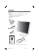
Contents Your new NEC MultiSync® LCD monitor box* should contain the following: • • • • • • MultiSync LCD1980SXi™ monitor with tilt/swivel/pivot/adjustable stand Power Cord Video Signal Cable (15-pin mini D-SUB male to DVI-A) Video Signal Cable (DVI-D to DVI-D cable) User’s Manual Cable Cover Power Cord 15-pin mini D-SUB male to DVI-A Cable Cover DVI-D to DVI-D cable MultiSync LCD1980SXi ® TM User’s Manual * Remember to save your original box and packing material to transport or ship the monitor.
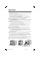
Quick Start To attach the MultiSync® LCD monitor to your system, follow these instructions: 1. Turn off the power to your computer. 2. For the PC or MAC with DVI digital output: Connect the DVI signal cable to the connector of the display card in your system (Figure A.1). Tighten all screws. For the PC with Analog output: Connect the 15-pin mini D-SUB to DVI-A signal cable to the connector of the display card in your system (Figure A.2).
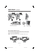
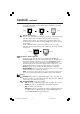
Quick Start –continued INPUT1 INPUT2 INPUT1 INPUT2 Figure C.2 Figure C.1 NEC optional product attachment. Do not use this connector unless specified. Vacation Switch Figure D.1 Raise and Lower Monitor Screen The monitor may be raised or lowered in either Portrait or Landscape mode. To raise or lower screen, place hands on each side of the monitor and lift or lower to the desired height (Figure RL.1). NOTE: Handle with care when raising or lowering the monitor screen. Figure RL.
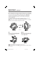
Quick Start –continued Screen Rotation Before rotating, the screen must be raised to the highest level to avoid knocking the screen on the desk or pinching your fingers. To raise the screen, place hands on each side of the monitor and lift up to the highest position (Figure RL.1). To rotate screen, place hands on each side of the monitor screen and turn clockwise from Landscape to Portrait or counter-clockwise from Portrait to Landscape (Figure R.1).
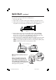
Quick Start –continued Remove Monitor Stand for Mounting To prepare the monitor for alternate mounting purposes: 1. Disconnect all cables. 2. Place hands on each side of the monitor and lift up to the highest position. 3. Place monitor face down on a nonabrasive surface. (Place the screen on a 33 mm platform so that the stand is parallel with the surface.) (Figure S.1) 33mm Figure S.1 4. Remove the two top screws connecting the monitor to the stand (Figure S.2).
Controls OSM® (On-Screen Manager) control buttons on the front of the monitor function as follows: To access OSM menu, press any of the control buttons ( , , –, +). To change signal input, press the SELECT button. NOTE: OSM must be closed in order to change signal input. Menu EXIT Exits the OSM controls. Exits to the OSM main menu. CONTROL / Moves the highlighted area left/right to select control menus. Moves the highlighted area up/down to select one of the controls.
Controls –continued Use left/Right Menu to center the image on the screen. If the H.Size or V.Size is wrongly calibrated, the result would look like the left drawing. The image should be homogeneous. Wrong Correct FINE (Analog input only) Improves focus, clarity and image stability by increasing or decreasing this setting. If the “Auto Adjust function” and the “H.Size” function do not give you a satisfactory picture setting, a fine tuning can be performed using the “Fine” function.
Controls –continued CUSTOM2: Zoom with top left corner fixed. The image is expanded from the rate of 1.00 to 3.00 times individually for horizontal (H.EXPANSION) and vertical (V.EXPANSION) direction by 0.01 step. VIDEO DETECT: Selects the method of video detection when more than one computer is connected. FIRST DETECT: The video input has to be switched to “FIRST DETECT” mode. When the current video input signal is not present, then the monitor searches for a video signal from the other video input port.
Controls –continued OSM TURN OFF: The OSM control menu will stay on as long as it is use. In the OSM Turn Off submenu, you can select how long the monitor waits after the last touch of a button to shut off the OSM control menu. The preset choices are 10120 seconds by 5 second increments. OSM LOCK OUT: This control completely locks out access to all OSM control functions. When attempting to activate OSM controls while in the Lock Out mode, a screen will appear indicating the OSM controls are locked out.
Long Cable Compensation Adjustment Long Cable Compensation should only be performed when using extended length cables or to compensate for a low-quality video signal. To perform the long cable compensation adjustment, follow these six steps: 1. For optimal adjustment, download the “LCD Long Cable Comp Test Pattern” and “Read Me” file at www.necmitsubishi.com and display the test pattern during this adjustment. 2. In order to perform the adjustment, enter the Advanced OSM: • Turn off your monitor.
Recommended Use Safety Precautions and Maintenance FOR OPTIMUM PERFORMANCE, PLEASE NOTE THE FOLLOWING WHEN SETTING UP AND USING THE MULTISYNC® LCD COLOR MONITOR: • DO NOT OPEN THE MONITOR. There are no user serviceable parts inside and opening or removing covers may expose you to dangerous shock hazards or other risks. Refer all servicing to qualified service personnel. • Do not spill any liquids into the cabinet or use your monitor near water.
Recommended Use –continued • • • • • • • • • • • • CORRECT PLACEMENT AND ADJUSTMENT OF THE MONITOR CAN REDUCE EYE, SHOULDER AND NECK FATIGUE. CHECK THE FOLLOWING WHEN YOU POSITION THE MONITOR: For optimum performance, allow 20 minutes for warm-up. Adjust the monitor height so that the top of the screen is at or slightly below eye level. Your eyes should look slightly downward when viewing the middle of the screen.
Specifications Monitor Specifications MultiSync® LCD1980SXi™ Monitor LCD Module Diagonal: Viewable Image Size: Native Resolution (Pixel Count): Input Signal Video: Sync: 19.0 inch 19.0 inch 1280x1024 Notes Active matrix; thin film transistor (TFT) liquid crystal display (LCD); 0.294 mm dot pitch; 270cd/m2 white luminance (typical); XtraView+™ technology; 500:1 contrast ratio (typical) ANALOG 0.7 Vp-p/75 Ohms Digital Input: DVI Separate sync. TTL Level Horizontal sync.
Features ambix+™ Technology: Dual input technology allowing both analog and digital inputs off of one connector (DVI-I) as well as additional legacy analog support off of a traditional 15-pin VGA connector. Provides traditional MultiSync® technology compatibility for analog as well as DVI-based digital compatibility for digital inputs. DVI-based digital interfaces include DVI-D,DFP and P&D.
Features –continued IPM® (Intelligent Power Manager) System: Provides innovative power-saving methods that allow the monitor to shift to a lower power consumption level when on but not in use, saving two-thirds of your monitor energy costs, reducing emissions and lowering the air conditioning costs of the workplace. Multiple Frequency Technology: Automatically adjusts monitor to the display card’s scanning frequency, thus displaying the resolution required.
Troubleshooting No picture • • • • • • • • • The signal cable should be completely connected to the display card/computer. The display card should be completely seated in its slot. Check the Vacation Switch should be in the ON position. Front Power Switch and computer power switch should be in the ON position. Check to make sure that a supported mode has been selected on the display card or system being used. (Please consult display card or system manual to change graphics mode.
References NEC-Mitsubishi Monitor Customer Service & Support Customer Service and Technical Support: (800) 632-4662 Fax: (800) 695-3044 Parts and Accessories/Macintosh Cable Adapter: (888) NEC-MITS [888-632-6487] Customer Service Policies & Processes: http://www.necmitsubishi.com/css/ ServicePolicies/ServicePolicies.htm Online Technical Support Knowledge Base: http://www.necmitsubishi.com/ css/knowledgebase.cfm Customer Service & Technical Support Email: http://www.necmitsubishi.com/ css/techform.
Limited Warranty NEC-Mitsubishi Electronics Display of America, Inc. (hereinafter “NMD-A”) warrants this Product to be free from defects in material and workmanship and, subject to the conditions set forth below, agrees to repair or replace (at NMD-A’s sole option) any part of the enclosed unit which proves defective for a period of three (3) years from the date of first consumer purchase. Spare parts are warranted for ninety (90) days.
TCO’99 –Black Model Congratulations! You have just purchased a TCO’99 approved and labelled product! Your choice has provided you with a product developed for professional use. Your purchase has also contributed to reducing the burden on the environment and also to the further development of environmentally adapted electronics products.
TCO’99 –continued health effects, including reproductive damage in fisheating birds and mammals, due to the bioaccumulative* processes. Flame retardants have been found in human blood and researchers fear that disturbances in foetus development may occur. TCO’99 demand requires that plastic components weighing more than 25 grams must not contain flame retardants with organically bound chlorine and bromine. Flame retardants are allowed in the printed circuit boards since no substitutes are available.
TCO’03 –White Model Congratulations! The display you have just purchased carries the TCO’03 Displays label. This means that your display is designed, manufactured and tested according to some of the strictest quality and environmental requirements in the world. This makes for a high performance product, designed with the user in focus that also minimizes the impact on our natural environment.
Manufacturer’s Recycling and Energy Information NEC-Mitsubishi Electric Visual Systems Corp. is strongly committed to environmental protection and sees recycling as one of the company’s top priorities in trying to minimize the burden placed on the environment. We are engaged in developing environmentallyfriendly products, and always strive to help define and comply with the latest independent standards from agencies such as ISO (International Organisation for Standardization) and TCO (Swedish Trades Union).
Declaration of the Manufacturer We hereby certify that the color monitor MultiSync® LCD1980SXi (L193FH) is in compliance with Council Directive 73/23/EEC: – EN 60950-1 Council Directive 89/336/EEC: – EN 55022 – EN 61000-3-2 – EN 61000-3-3 – EN 55024 and marked with NEC-Mitsubishi Electric Visual Systems Corporation 4-13-23, Shibaura, Minato-Ku Tokyo 108-0023, Japan 24 LCD1980SXimanual060704.
AVERTISSEMENT AFIN D’ÉVITER TOUT RISQUE D’INCENDIE OU D’ÉLECTROCUTION, NE PAS EXPOSER CET APPAREIL À LA PLUIE OU À L’HUMIDITÉ. NE PAS UTILISER LA FICHE D’ALIMENTATION POLARISÉE AVEC UNE PRISE DE CORDON DE RALLONGE OU AUTRE PRISE SAUF SI LES BROCHES PEUVENT ÊTRE ENTIÈREMENT INTRODUITES. NE PAS OUVRIR LE BOÎTIER, LEQUEL CONTIENT DES COMPOSANTS À HAUTE TENSION. CONFIER TOUS TRAVAUX À DU PERSONNEL TECHNIQUE QUALIFIÉ.
Contenu La boîte* de votre nouveau moniteur NEC MultiSync® contient : • • • • • • Moniteur MultiSync LCD1980SXi™ sur tilt/tourillon se place/réglage Cordon d'alimentation Câble pour le signal vidéo (Mini D-SUB mâle 15 broches vers DVI-A) Câble pour le signal vidéo (Câble DVI-D vers DVI-D) Manuel de l’utilisateur Gaine de câble Cordon d'alimentation Mini D-SUB mâle 15 broches vers DVI-A Gaine de câble Câble DVI-D vers DVI-D ® TM MultiSync LCD1980SXi Manuel de l’utilisateur * Ne pas oublier de conserv
Mise en marche rapide Pour raccorder le moniteur MultiSync® LCD au système, suivez les directives ciaprès: 1. Mettez l’ordinateur hors tension. 2. Pour un PC ou un Mac équipé d’une sortie numérique DVI : Branchez le câble DVI-D - DVI-D au connecteur de la carte graphique de votre ordinateur (Figure A.1). Serrez toutes les vis. Pour un PC équipé d’une sortie analogique : Branchez le câble de signal mini-connecteur D-SUB à 15 broches - DVI au connecteur de la carte graphique de votre systéme (Figure A.2).
Mise en marche rapide –suite INPUT1 INPUT2 INPUT1 INPUT2 Figure C.2 Figure C.1 Fixation de produit NEC en option. N’utilisez pas ce connecteur sauf indication contraire. l’interrupteur de vacances Bouton d’alimentation Figure D.1 Levez et baissez l’écran du moniteur Le moniteur peut être levé ou baissé en mode Portrait ou Paysage. Pour lever ou baisser l’écran, placez les mains de chaque côté du moniteur et positionnez-le à la hauteur de votre choix. (Figure RL.1).
Mise en marche rapide –suite Rotation de l’écran Avant de tourner l’écran, celui-ci doit être levé au niveau maximum afin d’éviter tout choc contre le bureau ou de pincer vos doigts. Pour lever l’écran, placez les mains de chaque côté du moniteur et levez-le jusqu’à la hauteur maximum (Figure RL.1). Pour tourner l’écran, placez les mains de chaque côté du moniteur et tournez-le dans le sens horaire de Paysage à Portrait ou dans le sens inverse de Portrait à Paysage (Figure R.1).
Mise en marche rapide –suite Enlever le support du moniteur pour le montage Pour préparer le moniteur à différents types de montage : 1. Déconnectez tous les câbles. 2. Placez les mains de chaque côté du moniteur en le soulevant dans sa position la plus haute. 3. Placez le moniteur la face vers le bas sur une surface non abrasive (placez l’écran sur une plate-forme de 33 mm de manière à ce que le support soit parallèle à la surface) (Figure S.1). 33mm Figure S.1 4.
Commandes Les boutons de réglage OSM situés sur l’avant du moniteur fournissent les fonctions suivantes : Pour accéder au menu OSM, appuyez sur une des touches de commande ( , , –, +). À transformer signale de l’entrée, presser le SELECT bouton. NOTA: Menu de OSM doit être fermé pourvoir modifier le signal déntrée et pour. Menu principal Quitte les commandes OSM. EXIT Revient au menu principal OSM. CONTROL / Déplace la zone en surbrillance vers la gauche ou la droite pour choisir un menu de commande.
Commandes –suite Si la fonction « Réglage AUTOMATIQUE » ne vous permet pas d’effectuer un réglage de l’image satisfaisant, il est possible d’effectuer une mise au point manuellement en utilisant la fonction « H.Size (ou V.Size) ». Pour cela, un motif de test moiré peut être utilisé. Cette fonction peut modifier la largeur ou Hauteur de l’image. Utilisez le menu gauche/droite pour centrer l’image sur l’écran. Si la largeur est mal calibrée, le résultat sera semblable à celui du dessin ci-contre.
Commandes –suite PERSONNALISÉ2 : Faites un zoom en fixant le coin supérieur gauche. L’image est agrandie individuellement au taux de 1,00 à 3,00 fois horizontalement (H.EXPANSION) et verticalement (V.EXPANSION) de 0,01 cran. DÉTECTION VIDÉO : Sélectionne la méthode de détection de la vidéo lorsque plusieurs ordinateurs sont connectés. 1ER DÉTECTÉ : L’entrée vidéo doit être commutée en mode « 1ER DÉTECTÉ ».
Commandes –suite lorsque ce dernier est en mode verrouillé, provoque l’apparition d’un écran informant que les commandes OSM sont verrouillées. Il existe trios types de VERROUILLAGE OSM : VERROUILLAGE OSM avec les commandes LUMINOSITÉ et CONTRASTE : Pour activer la fonction de verrouillage OSM, appuyez sur le bouton SÉLECTION, puis sur la touche « + » et maintenez-les simultanément enfoncés.
Réglage de la compensation de câble long La compensation des câbles longs ne peut être effectuée qu’avec des câbles rallongés ou pour compenser un signal vidéo de qualité médiocre. Il est nécessaire de suivre les étapes suivantes pour effectuer le réglage de compensation de câble long : 1. Pour un réglage optimal, téléchargez « LCD Long Cable Comp Test Pattern » et le fichier « Read Me » sur www.necmitsubishi.com et affichez le motif de test pendant ce réglage. 2.
Usage recommandé Consignes de sécurité et d’entretien POUR UN FONCTIONNEMENT OPTIMAL, PRIÈRE DE NOTER CE QUI SUIT POUR LE RÉGLAGE ET L'UTILISATION DU MONITEUR COULEUR MULTISYNC® LCD : • NE PAS OUVRIR LE MONITEUR. Aucune pièce intérieure ne nécessite l'intervention de l'utilisateur, et l'ouverture ou la dépose des couvercles peut entraîner des risques de décharges électriques dangereuses ou d'autres risques. Confier tous travaux à du personnel technique qualifié.
Usage recommandé –suite LA MODIFICATION DE LA POSITION ET DU RÉGLAGE DU MONITEUR PEUT RÉDUIRE LA FATIGUE DES YEUX, DES ÉPAULES ET DE LA NUQUE. OBSERVER LES DIRECTIVES CI-APRÈS LORS DU POSITIONNEMENT DU MONITEUR : • Pour une performance optimale, laissez le moniteur se réchauffer pendant 20 minutes. • Régler la hauteur du moniteur de sorte que le dessus de l'écran soit au niveau ou légèrement en-dessous du niveau des yeux.
Fiche technique Caractér. techn. du moniteur Module LCD Moniteur MultiSync® LCD1980SXi™ Diagonale : Surface utile : Résolution (nombre de pixels) : 19,0 po 19,0 po Paysage : 1280 x 1024 Vidéo : Sync : Signal d'entrée 16.777.216 Horizontale : Verticale : Automatique Automatique +88˚ (CR>10) +88˚ (CR>10) 25ms (May.
Fonctions Technologie ambix+™ : À double entrée permettant des entrées analogique et numérique à partir du même connecteur (DVI-I) ainsi que le support de matériel analogique existant à partir d’un connecteur VGA à 15 broches conventionnel. Assure la compatibilité avec la technologie MultiSync ® traditionnelle pour les entrées analogiques ainsi que la compatibilité numérique basée sur DVI pour les entrées numériques. Les interfaces numériques basées DVI incluent DVI-D, DFP et P&D.
Fonctions –suite facilite la configuration et l'installation en permettant au moniteur d'envoyer ses capacités (telles que le format et les résolutions d'écran acceptés) directement à l'ordinateur, optimisant ainsi automatiquement les performances d'affichage.
Dépannage Pas d'image • Le câble vidéo doit être bien connecté à la carte d'affichage et à l’ordinateur. • La carte d'affichage doit être insérée à fond dans son logement. • Vérifiez que l’interrupteur de vacances soit sur la position MARCHE. • Les interrupteurs d’alimentation du moniteur à l’avantet de l’ordinateur doivent être sur la position MARCHE.
Références Service à la clientèle et assistance technique du moniteur NEC-Mitsubishi Service à la clientèle et assistance technique: (800)632-4662 Télécopieur: (800) 695-3044 Pièces et accessoires/adaptateur de câble Macintosh: (888) NEC-MITS [888-632-6487] Politiques et processus du service à la clientèle: http://www.necmitsubishi.com/css/ ServicePolicies/ServicePolicies.htm Base de connaissance de l’assistance technique en lign: http://www.necmitsubishi.com/css/ knowledgebase.
Garantie limitée NEC-Mitsubishi Electronics Display of America, Inc. (ci-après «NMD-A») garantit que ce produit est exempt de vice de fabrication et de main-d’oeuvre et, selon les conditions énoncées ci-dessous, accepte de réparer ou remplacer, à sa discrétion, toute pièce de l’appareil concerné qui s’avérerait défectueuse et ce, pendant une période de trois (3) ans à partir de la date d’achat initial. Les pièces de rechange sont garanties pendant quatre-vingt dix (90) jours.
TCO’99 – le modèle noir (C’est une traduction de portion Anglaise de TCO’03.) Félicitations! Vous avez acheté un produit qui répond à la directive TCO’99. En choisissant ce produit conçu pour une utilisation professionnelle, vous contribuez aussi à la réduction des effets nuisibles sur l’environnement et aussi au développement continu de produits électroniques respectueux de l’environnement.
TCO’99 –suite 25 grammes ne contiennent pas de retardateurs de flame contenant du chlore ou du brome organiquement liés. Les retardateurs de flame sont autorisés dans les cartes à circuits imprimés étant donné qu’aucun substitut n’est encore disponible. Plomb** Le plomb peut être présent dans les tubes cathodiques, les écrans, les soudures et les condensateurs. Le plomb s’attaque au système nerveux et, à doses élevées, entraîne l’intoxication par le plomb.
TCO’03 – le modèle blanc (C’est une traduction de portion Anglaise de TCO’03.) Félicitations ! L’écran que vous venez d'acheter porte l’étiquette « Displays TCO’03 ». Ceci signifie que votre écran a été conçu, fabriqué, et vérifié selon certaines des directives relatives à la qualité et aux exigences environnementales les plus strictes au monde. Cela permet à un produit de haute performance, conçu avec l’utilisateur comme priorité, de réduire son impact sur notre environnement naturel.
Informations du fabricant relatives au recylage et aux économies d’énergie NEC-Mitsubishi Electric Visual Systems Corp. S’est fortement engagée dans la protection de l’environnement et voit le recyclage comme une des priorités de la société en essayant de réduire la pression exercée sur l’environnement.
Déclaration du fabricant Nous certifions par la présente que les moniteurs MultiSync® LCD1980SXi (L193FH) sont conformes à la directive 73/23/EEC du Counseil: – EN 60950-1 la directive 89/336/EEC du Counseil: – EN 55022 – EN 61000-3-2 – EN 61000-3-3 – EN 55024 et porte le sigle NEC-Mitsubishi Electric Visual Systems Corporation 4-13-23, Shibaura, Minato-Ku Tokyo 108-0023, Japan 48 LCD1980SXimanual060704.
Appendix If you need detailed information about the controls, please use the advanced menu. How to use the advanced menu • Turn off your monitor. • Turn on your monitor by pushing the "POWER" and "SELECT" button at the same time for at least one second simultaneously. • You will see the Advanced menu. This menu is larger than the normal OSM. How to exit the advanced menu • Turn off and restart your monitor in the normal way. To make an adjustment, ensure that the tag is highlighted, then press "SELECT.
Appendix –continued Tag 3 Signal Determines when the auto adjust is performed. The choices are “OFF”, “SIMPLE” and “FULL”. Press “+” or “-” to select. (Analog input only) Signal Setting Input Signal New signal OFF SIMPLE FULL Adjustment Items Re-input "H-size" "Fine" "H/V-Position" Contrast X O O * * X * * O O O X O : Automatic adjustment is performed on adjustments marked with *. X : Automatic adjustment is not performed.
Appendix –continued Fine (Analog input only) If the “Auto Adjust function” and the “H.Size” function do not give you a satisfactory picture setting, fine tuning can be performed using the “Fine” function. Increasing or decreasing this setting can improve focus, clarity and image stability. For this a Moiré test pattern could be used. If the Fine value is wrongly calibrated, the result would look like the drawing on the left. The image should be homogeneous.
Appendix –continued The color temperature and tone that were set up with the downloaded application software are reflected. Tag7 Sharpness Press “+” or “-” to adjust. This is a digital capability for keeping a crisp image at all signal timings. It continuously adjusts to maintain a distinct or soft image as preferred, and is set independently according to different timings. Expansion Mode Sets the zoom method. FULL: The image is expanded to 1280 x 1024, regardless of the resolution.
Appendix –continued OSM Position You can choose where you would like the OSM control image to appear on your screen. Selecting OSM Location allows you to manually adjust the position of the OSM control menu left, right, down or up. Press “SELECT” to move the adjustment menu, and press “+” or “-” to adjust. OSM Turn off The OSM control menu will stay on as long as it is in use.
Appendix –continued Tile Comp Works in tandem with Tile Matrix (Tag9) to compensate for the width of the tile bezels in order to accurately display the image. Tile Comp ON Sync Threshold (Analog input only) Tile Comp OFF Adjusts the slice level of a synchronization signal. Press “+” or “–” to select.
Annexe Si vous avez besoin de plus amples informations au sujet des commandes, veuillez utiliser le menu avancé. Comment utiliser le menu avancé • Mettez votre moniteur hors tension. • Mettez votre moniteur en marche en appuyant simultanément sur les boutons « MARCHE » et « SELECT » pendant au moins une seconde. • Le menu avancé s’affiche. Ce menu est plus grand que le menu OSM habituel.
Annexe –suite Onglet2 Position R-H (Entrée analogique seulement) Position G-H (Entrée analogique seulement) Position B-H (Entrée analogique seulement) PRÉCISION R (Entrée analogique seulement) PRÉCISION G (Entrée analogique seulement) PRÉCISION B (Entrée analogique seulement) Ajuste la position de la composante rouge de l’image. Appuyez sur «+» ou «-» pour effectuer le réglage. Ajuste la position de la composante verte de l’image. Appuyez sur «+» ou «-» pour effectuer le réglage.
Annexe –suite Règle le « Niveau de réglage automatique » tel qu’illustré dans le tableau ci-dessous. SIMPLE COMPLET DÉTAIL "Dimension" "précision" "Position" O O O "Contraste" Niveau du noir, Capacité du câble long *1 Durée X O O X X O 1,5 secondes 2 secondes 10 à 20 secondes O : Le réglage automatique est effectué. X : Le réglage automatique n’est pas fait. *1 : Le niveau du noir, la précision RVB, le temps de retard RVB et la position RVB sont réglés à l’aide du logiciel Câble long.
Annexe –suite faire, vous devrez utiliser un motif de test Moiré. Si la valeur Précision n’est pas correctement étalonnée, vous allez obtenir le résultat illustré sur le dessin de gauche. L’image doit être homogène. Onglet5 Sélection gamma Vous permet de sélectionner manuellement le niveau de luminosité de l’échelle de gris. Il existe cinq sélections : NO CORRECTION, 2.2, OPTION, PROGRAMMABLE et CUSTOM. NO CORRECTION : Aucune correction possible. 2.2: La valeur est fixée à 2.2.
Annexe –suite Onglet7 Précision Appuyez sur «+» ou «-» pour effectuer le réglage. Cette fonction utilise la technologie numérique pour conserver une image contrastée avec toute synchronisation des signaux. Il effectue continuellement l’ajustement afin de maintenir une image distincte ou estompée, selon vos préférences, et il se règle indépendamment d’après les différentes synchronisations. Mode Expansion Règle la méthode de zoom. COMPLET : L’image est agrandie à 1280 x 1024, quelle que soit la résolution.
Annexe –suite Langue Les menus de contrôle OSM sont disponibles en sept langues. Appuyez sur «+» ou «-» pour sélectionner. Position OSM Vous pouvez choisir l’endroit où vous souhaitez que l’image de contrôle OSM apparaisse à l’écran. Le fait de sélectionner l’emplacement OSM vous permet d’ajuster manuellement la position du menu de contrôle OSM à gauche, à droite, en bas ou en haut. Appuyez sur « SELECT » pour déplacer le menu d’ajustement et appuyez sur «+» ou «-» pour effectuer le réglage.
Annexe –suite Onglet8 RapidMotion Tile Comp Ce mode peut être utilisé pour visionner une vidéo mobile (comme un DVD ou MPEG) sur le moniteur. RapidMotion va contourner la reproduction vidéo sans image dédoublée ou artefact numérique. Pour de meilleurs résultats, RapidMotion doit être utilisé lorsque vous êtes en résolution naturelle (1280 x 1024). Fonctionne en tandem avec TileMatrix (Tag9) pour compenser la largeur des encadrements empilés afin d’afficher l’image avec précison.
Notes 62 LCD1980SXimanual060704.
Notes 63 LCD1980SXimanual060704.
Notes 64 LCD1980SXimanual060704.
Série LCD NEC AVIS DE PROPRIÉTÉ EXCLUSIVE ET DE DÉGAGEMENT DE RESPONSABILITÉ Les informations contenues dans ce document, y compris tous les designs et matériel s'y rapportant, sont la propriété de NEC-Mitsubishi Electronics Display of America et/ou ses concédants.
NEC LCD Series PROPRIETARY NOTICE AND LIABILITY DISCLAIMER The information disclosed in this document, including all designs and related materials, is the valuable property of NECMitsubishi Electronics Display of America and/or its licensors, as appropriate, reserve all patent, copyright and other proprietary rights to this document, including all design, manufacturing, reproduction, use and sales rights thereto, except to the extent said rights are expressly granted to others.