MultiSync LCD3090WQXi User’s Manual
Index Warning, Caution ........................................................................................................................ English-1 Declaration .................................................................................................................................. English-1 Canadian Department of Communications Compliance Statement ............................................ English-2 Declaration of Conformity .................................................................
TO PREVENT FIRE OR SHOCK HAZARDS, DO NOT EXPOSE THIS UNIT TO RAIN OR MOISTURE. ALSO, DO NOT USE THIS UNIT'S POLARIZED PLUG WITH AN EXTENSION CORD RECEPTACLE OR OTHER OUTLETS UNLESS THE PRONGS CAN BE FULLY INSERTED. REFRAIN FROM OPENING THE CABINET AS THERE ARE HIGH VOLTAGE COMPONENTS INSIDE. REFER SERVICING TO QUALIFIED SERVICE PERSONNEL. CAUTION CAUTION: TO REDUCE THE RISK OF ELECTRIC SHOCK, MAKE SURE POWER CORD IS UNPLUGGED FROM WALL SOCKET.
Canadian Department of Communications Compliance Statement DOC: This Class B digital apparatus meets all requirements of the Canadian Interference-Causing Equipment Regulations. C-UL: Bears the C-UL Mark and is in compliance with Canadian Safety Regulations according to CAN/CSA C22.2 No. 60950-1. FCC Information 1. Use the attached specified cables with the MultiSync LCD3090WQXi color monitor so as not to interfere with radio and television reception.
Safety Precautions and Maintenance FOR OPTIMUM PERFORMANCE, PLEASE NOTE THE FOLLOWING WHEN SETTING UP AND USING THE LCD COLOR MONITOR: • DO NOT OPEN THE MONITOR. There are no user serviceable parts inside and opening or removing covers may expose you to dangerous shock hazards or other risks. Refer all servicing to qualified service personnel. • Do not spill any liquids into the cabinet or use your monitor near water.
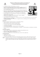
CORRECT PLACEMENT AND ADJUSTMENT OF THE MONITOR CAN REDUCE EYE, SHOULDER AND NECK FATIGUE. CHECK THE FOLLOWING WHEN YOU POSITION THE MONITOR: • For optimum performance, allow 20 minutes for warm-up. • Adjust the monitor height so that the top of the screen is at or slightly below eye level. Your eyes should look slightly downward when viewing the middle of the screen. • Position your monitor no closer than 40 cm and no further away than 70 cm from your eyes. The optimal distance is 50 cm.
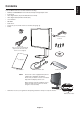
English Contents Your new NEC monitor box* should contain the following: • MultiSync LCD3090WQXi monitor with tilt/swivel/pivot/height adjust stand • Power Cord • Video Signal Cable (15-pin mini D-SUB male to DVI-A) • Video Signal Cable (DVI-D to DVI-D cable) • User’s Manual • CD-ROM • Cable Cover • Screw (x 4) (to mount the monitor to a flexible arm (page 9)) • Clamp Clamp 15-pin mini D-SUB male to DVI-A Power Cord (Type of power cord included will depend on the where the LCD monitor i
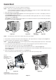
Quick Start To attach the LCD monitor to your system, follow these instructions: NOTE: Make sure to read “Recommended Use” before installation. In order to display the maximum resolution, a video card that can output a resolution of 2560 x 1600 is needed. The monitor must be installed or carried by two or more people. 1. Turn off the power to your computer. 2. For the PC or MAC with DVI digital output: Connect the DVI signal cable to the connector of the display card in your system (Figure A.1).
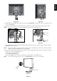
English Figure C.4 Figure C.3 7. Hold all cables firmly and place the cable cover onto the stand (Figure D.1). To remove the cable cover, lift the cover off as shown in Figure D.2. 8. Connect one end of the power cord to the AC inlet on the back of the monitor and the other end to the power outlet. NOTE: Please refer to Caution section of this manual for proper selection of AC power cord. Figure D.1 Figure D.2 9. The Vacation Switch on the left side of the monitor must be turned on.
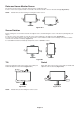
Raise and Lower Monitor Screen The monitor may be raised or lowered in either Portrait or Landscape mode. To raise or lower screen, place hands on each side of the monitor and lift or lower to the desired height (Figure RL.1). NOTE: Handle with care when raising or lowering the monitor screen. Figure RL.1 Screen Rotation Before rotating, the screen must be raised to the highest level to avoid knocking the screen on the desk or pinching with your fingers.
English Flexible Arm Installation This LCD monitor is designed for use with a flexible arm. To prepare the monitor for alternate mounting purposes: NOTE: The monitor must be installed or moved by two or more people. • Refer to instructions included with the flexible arm for detailed instructions. • To fulfill the safety requirements the monitor must be mounted to an arm, which guaranties the necessary stability under consideration of the weight of the monitor. Remove Monitor Stand 1.
Controls OSD (On-Screen Display) control buttons on the front of the monitor function as follows: To access OSD menu, press the MENU button. To change signal input, press the SELECT button. NOTE: OSD must be closed in order to change signal input. 8 7 Landscape 1 2 3 4 5 9 6 Portrait 1 AUTO DIMMING SENSOR Detects the level of ambient light, allowing the monitor to make adjustments to various settings, resulting in a more comfortable viewing experience. Do not cover this sensor.
English Brightness/Contrast Controls BRIGHTNESS Adjusts the overall image and background screen brightness. NOTE: The upper portion (higher settings) of the brightness level is adjusted using the backlight output. If a very low brightness level (low setting) is used the contrast level may be reduced. The display will digitally compensate for low brightness level. If this occurs, the indicator on the OSD will turn magenta. CONTRAST Adjusts the image brightness in relation to the background.
FINE (Analog input only) Improve focus, clarity and image stability by increasing or decreasing this setting. If the “Auto Adjust function” and the “H.Size” function do not give you a satisfactory picture setting, a fine tuning can be performed using the “Fine” function. For this a Moiré test pattern could be used. If the Fine value is wrongly calibrated, the result would look like the left drawing. The image should be homogeneous. When FINE value is wrong. When FINE value is correct.
Selects the type of input to be used with HDCP CONTENT. OFF: When a PC or other computer equipment is connected, select “OFF”. ON: When a DVD player or other type of high definition device is connected, select “ON”. NOTE: Interlaced signals (480i, 576i, 1080i) are not supported. If you have any problems, please refer to the Troubleshooting section of this User’s Manual. VIDEO DETECT Selects the method of video detection when more than one video input is connected.
OSD LOCK OUT This control completely locks out access to all OSD control functions. When attempting to activate OSD controls while in the Lock Out mode, a screen will appear indicating the OSD controls are locked out. There are four types of OSD LOCK OUT: OSD LOCK OUT with BRIGHTNESS and CONTRAST control: To activate the OSD Lock Out function, press SELECT, then the “UP” button and hold down simultaneously.
Monitor Specifications MultiSync LCD3090WQXi Monitor LCD Module Diagonal: 75.6 cm/29.8 inches Viewable Image Size: 75.6 cm/29.8 inches Native Resolution (Pixel Count): 2560 x 1600 Input Signal Notes Active matrix; thin film transistor (TFT) liquid crystal display (LCD); 0.251 mm dot pitch; 350 cd/m2*2 white luminence; 1000:1*2 contrast ratio, typical. Video: ANALOG 0.7 Vp-p/75 Ohms Digital Input: DVI (with HDCP) Sync: Separate sync.TTL Level Horizontal sync. Positive/Negative Vertical sync.
Features DVI-I: The integrated interface ratified by the Digital Display Working Group (DDWG) that allows both digital and analog connectors off of one port. The “I” stands for integration for both digital and analog, The digital portion is DVI-based. DVI-D: The digital-only subset of DVI ratified by the Digital Display Working Group (DDWG) for digital connections between computers and displays. As a digital-only connector, analog support is not provided off a DVI-D connector.
No picture • The signal cable should be completely connected to the display card/computer. • The display card should be completely seated in its slot. • Check the Vacation Switch should be in the ON position. • Front Power Switch and computer power switch should be in the ON position. • Check to make sure that a supported mode has been selected on the display card or system being used. (Please consult display card or system manual to change graphics mode.
Appendix If you need detailed information about the controls, please use the advanced menu. • Turn off your monitor. • Turn on your monitor by pushing the “POWER” and “SELECT” button at the same time for at least one second simultaneously. Then press the control buttons (EXIT, LEFT, RIGHT, UP, DOWN). • You will see the Advanced menu. This menu is larger than the normal OSD. • Turn off and restart your monitor in the normal way.
Tag3 R-H.position (Analog input only) Adjusts the position of the red component of the image. Press “Left” or “Right” to adjust. G-H.position (Analog input only) Adjusts the position of the green component of the image. Press “Left” or “Right” to adjust. B-H.position (Analog input only) Adjusts the position of the blue component of the image. Press “Left” or “Right” to adjust. R-FINE (Analog input only) Adjusts the “FINE” setting of the RED component of the image. Press “Left” or “Right” to adjust.
H. Size (Analog input only) Adjusts the horizontal size of the screen. If the “AUTO Adjust function” do not give you a satisfactory picture setting, a further tuning can be performed using the “H.Size (V.Size)” function (dot clock). For this a Moiré test pattern could be used. This function may alter the width of the picture. Use left/Right Menu to center the image on the screen. If the H.Size (V.Size) is wrongly calibrated, the result would look like the left drawing. The image should be homogeneous.
Color Control Color Control Systems: Seven preset color settings. For preset settings 1, 2, 3 and 5, the following levels can be adjusted: TEMPERATURE: Adjust the white temperature by increasing or decreasing this setting. A lower color temperature will make the screen reddish and a higher color temperature will make the screen bluish. WHITE (White Balance): If TEMPERATURE needs further adjustment; the individual R/ G/ B/ levels of the white point can be adjusted.
Tag8 Response Improve Turns the RESPONSE IMPROVE function on or off. Response Improve may reduce blurring that occurs in some moving images. When Response Improve is on, response time is improved. Side Border Color Adjusts the side black bars color between black and white. For wide aspect monitors. LED Brightness Controls the brightness of the LED on the monitor. LED Color The LED on the front can be blue or green.
Tag9 When this function is activated; the brightness and contrast of the monitor can be adjusted without entering the OSD menu by using the front buttons. The “Left” or “Right” buttons adjust the brightness level. The “Down” or “Up” buttons adjust the contrast level. Factory Preset Selecting Factory Preset allows you to reset all OSD control settings back to the factory settings. Highlighting the control to be reset and pressing the RESET button can reset individual settings.
TagA Tile Matrix The Tile Matrix feature allows one image to be displayed over multiple screens. This feature can be used with up to 25 monitors (5 vertical and 5 horizontal). Using Tile Matrix requires the PC output signal be sent through a distribution amplifier to each individual monitor. ENABLE: Select “ON”, the monitor will expand the selected position. H MONITOR: Select the number of horizontal displays. V MONITOR: Select the number of vertical displays.
Simply connect the external USB sensor, and the brightness, white tint and gamma levels are calibrated without the need of a computer. This feature works for displays requiring RGB calibration and graphical calibration. Before proper self calibration can be performed, display should warm-up for a minimum 30 minutes. If the USB sensor is plugged in before the monitor is warmed up, a warning will appear on-screen (Figure S.3).
7. The procedure will ask for the USB sensor to be placed on the center of the display panel (Figure S.7). Tilt the display panel approximately 5˚ backward and place the USB sensor in the center of the display panel (Figure S.1). NOTE: Place the USB sensor flat against the LCD to avoid external light contamination. DO NOT press the calibrator against the display panel. Press “SELECT”. 8. Set the target LUMINANCE (cd/m2) (Figure S.8). Figure S.6 Figure S.7 Figure S.8 9.
Calibration settings can be copied from one display to one or more additional displays. Using this feature reduces the variation between different displays allowing them to match each other more closely. Before proper copy calibration can be performed, displays should warm-up for a minimum 30 minutes. If the sensor is plugged in before the minute warm-up, a warning will appear on-screen (Figure C.4). NOTE: Stand-alone calibration can only be performed using the X-Rite i1 Display Sensor.
6. Using “LEFT” or “RIGHT” of Display B, select COPY in the MODE selection (Figure C.7). Select ON of OFF in the SELF selection. If ON selected, SELF Calibration execute with COPY Calibration. 7. Select the target GAMMA: NO CORRECTION, 2.2, OPTION, PROGRAMMABLE and CUSTOM. Please select the same target GAMMA as Display A. NOTE: If CUSTOM is selected, the Gamma Value can be manually changed in intervals of 0.1 at 0.5-4.0. 8.
The brightness of the LCD screen can be set to increase or decrease depending on the amount of ambient light within the room. If the room is bright, the monitor becomes correspondingly bright. If the room is dim, then the monitor will dim accordingly. The purpose of this function is to make the viewing experience more comfortable to the eye in a variety of lighting conditions. The Auto Brightness function is set to OFF by default. NOTE: When “AUTO LUMINANCE” is ON, this function is disabled.
TCO’03 Congratulations! The display you have just purchased carries the TCO’03 Displays label. This means that your display is designed, manufactured and tested according to some of the strictest quality and environmental requirements in the world. This makes for a high performance product, designed with the user in focus that also minimizes the impact on our natural environment.
(TCO’06 compliant with Response Improve feature set ON (see page 22 in this manual). Congratulations! The product you have just purchased carries the TCO’06 Media Displays label. This means that your display is designed and manufactured according to some of the strictest performance and environmental criteria in the world. The manufacturer of this display has selected it to be certified to TCO’06 Media Displays as a sign of usability, high performance and reduced impact on the natural environment.
Manufacturer’s Recycling and Energy Information NEC DISPLAY SOLUTIONS is strongly committed to environmental protection and sees recycling as one of the company’s top priorities in trying to minimize the burden placed on the environment. We are engaged in developing environmentallyfriendly products, and always strive to help define and comply with the latest independent standards from agencies such as ISO (International Organisation for Standardization) and TCO (Swedish Trades Union).