MANUEL UTILISATEUR 32 To learn about other special offers, register online at www.necdisplay.
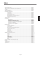
Important Information........................................................................................................................... English-2 Safety Precautions, Maintenance, & Recommended Use ................................................................ English-3 Contents ..................................................................................................................................................... English-4 Attaching LCD Options ........................................
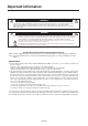
Important Information WARNING TO PREVENT FIRE OR SHOCK HAZARDS, DO NOT EXPOSE THIS UNIT TO RAIN OR MOISTURE. ALSO, DO NOT USE THIS UNIT’S POLARIZED PLUG WITH AN EXTENSION CORD RECEPTACLE OR OTHER OUTLETS UNLESS THE PRONGS CAN BE FULLY INSERTED. REFRAIN FROM OPENING THE CABINET AS THERE ARE HIGH VOLTAGE COMPONENTS INSIDE. REFER SERVICING TO QUALIFIED SERVICE PERSONNEL. CAUTION CAUTION: TO REDUCE THE RISK OF ELECTRIC SHOCK, MAKE SURE POWER CORD IS UNPLUGGED FROM WALL SOCKET.
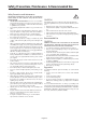
Safety Precautions, Maintenance & Recommended Use Safety Precautions and Maintenance • • • • • • • • • • • • When operating the MultiSync LCD3210 monitor with its AC 125-240V power supply, use a power supply cord that matches the power supply voltage of the AC power outlet being used. The power supply cord you use must have been approved by and comply with the safty standards of your country.
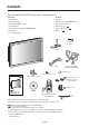
Contents Your new MultiSync® LCD3210 monitor box* should contain the following: • CD-ROM • • • • • • • LCD monitor Power Cord (3m) Video Signal Cable – (4m) User’s Manual Wireless Remote Control and AA Batteries Clamper x 3 Screw (M4 x 8) x 4 • • • • • • Stand x 2 Thumbscrew for stand (M4x27) x 2 Main switch cover x 1 Ferrite Core x 2 AV Speaker Plug x 1 set AV Band x 2 AV Thumbscrew for stand x 2 Stand x 2 Video Signal Cable Power Cord (D-SUB to D-SUB Cable) Clamper x 3 Screw (M4 x 8 ) x 4 Main sw
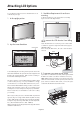
Attaching LCD Options You can attach mounting accessories to the LCD monitor in one of the following two ways: 3. Ventilation Requirements for enclosure mounting To allow heat to disperse, leave space between surrounding 1. In the upright position 4. To prevent the LCD Monitor from falling down Fasten the LCD monitor to a wall using a cord or chain which is sufficient to support the weight of the LCD monitor (approx. LCD3210 17.0kg). Before moving the LCD monitor, the cord or chain should be removed.
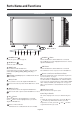
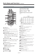
Parts Name and Functions Control Panel 9 10 OFF EXIT 7 8 6 5 4 INPUT MUTE 3 2 MUTE button Button Location 1 1 POWER button ( ) Switches the power on/off. See page 18. 2 ON 7 DOWN ( ) button Activates the OSM menu when the OSM menu is turned-off. Acts as button to move the highlighted area down to select the adjustment with OSM menu. AV Switches the audio mute ON/OFF. 3 8 INPUT button Acts as SET button within the OSM menu. Selects which signal connected to the display is shown.
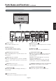
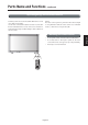
Parts Name and Functions -continued Terminal Panel English LCD monitor AC IN PC OUT PC IN RGB3 IN Cb/Pb Y H AUDIO VIDEO DVD/HD IN Cr/Pr S-VIDEO IN OUT OUT IN3 IN2 V SPEAKER OUT IN1 R R L IN RGB 1 (DVI-D) RGB 2 (D-SUB) RGB OUT (D-SUB) R 5 G 4 1 AC IN connector Connects with the supplied power cord. 2 RGB 2 IN (mini D-Sub 15 pin) To input analog RGB signals from a personal computer or other RGB equipment.
Parts Name and Functions -continued Wireless Remote Control 8 VOLUME DOWN button Decrease the audio output level. AV 9 PIP (Picture In Picture) button AV ON/OFF button: PIP ON/OFF. INPUT button: Select the ‘picture in picture’ input signal. CHANGE button: Replaces to the main picture and sub picture.
Parts Name and Functions -continued Operating Range for the Remote Control Point the top of the remote control toward the LCD monitor’s remote sensor while pressing button. Use the remote control within a distance of about 7 m/23 ft. from the front of the LCD monitor’s remote control sensor and at a horizontal and vertical angle of within 30 degree within a distance of about 3 m/10 ft.
Setup Procedure 1. Determine the installation location 4. Connect the supplied power cord CAUTION Installing your LCD display must be done by a qualified technician. Contact your dealer for more information. CAUTION MOVING OR INSTALLING THE LCD MONITOR MUST BE DONE BY TWO OR MORE PEOPLE. Failure to follow this caution may result in injury if the LCD monitor falls. • The equipment should be installed close to an easily accessible power outlet.
Setup Procedure -continued 10. Recommended Adjustments To reduce the risk of the “image persistence”, please adjust the following items based on the application being used. “SCREEN SAVER” (See page 24), see page ”SIDE BORDER COLOR” (See page 24), “DATE & TIME” (See page 27), “SCHEDULE” (See page 27) 11. When the monitor is installed in the portrait position Remove the stands (feet). Left edge should be the upper edge from front view. Speaker terminal English • • 12.
Connections Before connecting external equipment to LCD: * * First turn off the power to all of the equipment associated with the LCD as well as that of the equipment to be connected. For questions regarding external equipment please refer to the user’s manual supplied with that equipment.
Connections -continued Scanning frequency Horizontal Vertical Remarks 640 x 480 31.5Hz 60Hz 800 x 600 37.9H z 60Hz 1024 x 76 8 48.4Hz 60Hz 1280 x 76 8 48Hz 60Hz 1360 x 76 8 48Hz 60Hz Recommended resolution 1280 x 1024 64Hz 60Hz Compressed imag e 1 600 x 1200 7 5Hz 60Hz Compressed imag e Connecting the LCD Monitor to a PC Connecting your computer to your LCD monitor will enable you to display your computer’s screen image. Some video cards may not display an image correctly.
Connections -ontinued Connecting to a Macintosh� Computer Connecting your Macintosh® computer to your LCD monitor will enable you to display your computer’s screen image. Some video cards or drivers may not display images correctly. • To connect the RGB 2 IN connector (mini D-sub 15 pin) on the LCD monitor, use the provided RGB signal cable (mini D-sub 15 pin to mini D-sub 15 pin). For older Macintosh® computers, use Macintosh cable adapter to connect to your Macintosh’s video port.
Connections -continued Connecting to a Computer with a Digital Output Connections can be made with equipment that is equipped with a digital interface compliant with the DVI (Digital Visual Interface) standard. The RGB 1 IN connector also accepts a DVI-D cable. Input TMDS signals conforming to DVI standards. To maintain display quality, use a cable recommended by DVI standards. The AUDIO IN 1, 2 and 3 can be used for audio input. For connection, select AUDIO 1, 2 or 3 from the AUDIO INPUT button.
Connections -continued Connecting to a DVD Player AV Connecting your DVD player to your LCD monitor will enable you to display your DVD video. Refer to your DVD player’s owner’s manual for additional information. • To connect the DVD/HD IN connector (BNC) on the LCD monitor, use a separately available BNC connector cable. You will need a BNC-to-RCA adapter to connect a DVD player with an RCA pin jack to the BNC connector cable (not provided). The AUDIO IN 2 and 3 (both RCA) can be used for audio input.
Connections -continued Connecting to a Stereo Amplifier AV You can connect your stereo amplifier to your LCD monitor. Refer to your amplifier’s owner’s manual for additional information. Turn on the LCD monitor and the amplifier only after all connections have been made. Use an RCA cable to connect the AUDIO OUT connector (RCA) on the LCD monitor and the audio input on the amplifier. Do not reverse the audio left and right jacks. The AUDIO IN used for audio input.
Basic Operation -Power ON and OFF Modes The LCD monitor power indicator will turn green while powered on and will turn red while powered off. The monitor can be powered on or off using the following three options: 1. Pressing the power button. NOTE: Before pressing the power button, be sure to turn on the Main Power Switch on the LCD monitor. Power Button 2. Using the remote control NOTE: Before operating the remote control, be sure to turn on the Main Power Switch on the LCD monitor.
Basic Operation -continued Picture Mode Power Indicator Power Indicator Power ON Power OFF Power Standby when “SCHEDULE” is enabled Power Standby Diagnosis (Detecting failure) Status Green Red Red On Green Blinking Red , Green AV RGB 1, 2, 3 HIGHBRIGHT STANDARD sRGB DVD/HD, VIDEO HIGHBRIGHT STANDARD CINEMA Information OSM RGB1, 2, 3 Red Blinking *See trouble shooting of page 33 When Using Power Management Function The LCD monitor follows the VESA approved DPM Power Management function.
OSM (On-Screen Manager) Controls-Picture Press MENU button to open Main-menu Press UP or DOWN button to select sub-menu Press SET button to decide Press the UP, DOWN, PLUS, or MINUS buttons to select options and to make adjustments to settings Press SET button to select Press MENU or EXIT button to exit Remote Control SET SET Press UP or DOWN button to select Press INPUT button to decide SET SET Press EXIT button to exit Press the UP, DOWN, PLUS, or MINUS buttons to select options and to make adj
OSM Controls-Screen PICTURE TINT *:INPUT DVD/HD,VIDEO only BRIGHTNESS CONTRAST SHARPNESS TINT COLOR BLACK LEVEL NOISE REDUCTION Adjusts the tint of the screen. TINT 32 + -:ADJ EXIT :RETURN MENU :EXIT MENU :SEL SET :NEXT EXIT :RETURN MENU :EXIT MENU Adjusts the color depth of the screen.
OSM Controls-Audio V RESOLUTION *:INPUT RGB1/2/3 only SCREEN H POSITION V POSITION CLOCK CLOCK PHASE H RESOLUTION V RESOLUTION ZOOM MODE SCREEN RESET V RESOLUTION 768 + -:ADJ EXIT :RETURN MENU :EXIT MENU :SEL SET :NEXT EXIT :RETURN MENU :EXIT MENU SCREEN H POSITION V POSITION CLOCK CLOCK PHASE H RESOLUTION V RESOLUTION ZOOM MODE SCREEN RESET Selects the screen zoom mode. "ZOOM" mode can be selected pressing the "SIZE" button on the remote control.
OSM Controls-Configuration1 AV AV English AV AV AV English-23
OSM Controls-Configuration2 SCREEN SAVER CONFIGURATION 1 AUTO SETUP AUTO ADJUST AUTO BRIGHTNESS POWER SAVE LANGUAGE SCREEN SAVER SIDE BORDER COLOR :SEL SET :NEXT EXIT :RETURN MENU :EXIT MENU Select "SCREEN SAVER" settings to reduce the risk of "Image Persistence". GAMMA: The display gamma is changed and fixed when "ON" is selected. COOLING FAN: The built in cooling fan is always on when set to "ON". BRIGHTNESS: The brightness is decreased when "ON" is selected.
OSM Controls-Configuration2 OSM TURN OFF 10 SEC. + -:ADJ EXIT :RETURN MENU :EXIT MENU :SEL SET :NEXT EXIT :RETURN MENU :EXIT MENU INFORMATION OSM CONFIGURATION 2 LONG CABLE MANUAL OSM TURN OFF INFORMATION OSM OFF TIMER OSM POSITION INPUT DETECT MONITOR INFORMATION Selects whether the information OSM is displayed or not. The information OSM will be displayed when the input signal or source changes. the information OSM will also give a warning when there is no-signal or the signal is out-of range.
OSM Controls-Advanced option Main-Menu MAIN MENU PICTURE SCREEN AUDIO PIP CONFIGURATION 1 CONFIGURATION 2 ADVANCED OPTION ADVANCED OPTION :SEL SET :NEXT EXIT :RETURN MENU :EXIT MENU Sub-Menu AV S-VIDEO MODE ADVANCED OPTION S-VIDEO MODE BLACK LEVEL EXPANSION GAMMA SELECTION SCAN MODE SCAN CONVERSION FILM MODE TILE MATRIX S-VIDEO MODE PRIORITY / SEPARATE EXIT :RETURN MENU :EXIT MENU + -:SEL :SEL SET :NEXT EXIT :RETURN MENU :EXIT MENU Selects the S-Video input port function.
OSM Controls-Advanced option IR CONTROL IR CONTROL NORMAL LOCK IR CONTROL TILE MATRIX HEAT STATUS POWER ON DELAY DATE & TIME SCHEDULE ADVANCED OPTION RESET :SEL SET :NEXT EXIT :RETURN MENU :EXIT MENU SET :SET EXIT :RETURN The "TILE MATRIX" feature allows one image to be displayed on multiple screens. This feature can be used with up to 16 monitors.
OSM Controls-NOTE NOTE 1: IMAGE PERSISTENCE Please be aware that LCD Technology may experience a phenomenon known as Image Persistence. Image Persistence occurs when a residual or “ghost” image of a previous image remains visible on the screen. Unlike CRT monitors, LCD monitors’ image persistence is not permanent, but constant images being displayed for a long period of time should be avoided. To alleviate image persistence, turn off the monitor for as long as the previous image was displayed.
Using the LCD with a Personal Computer (PC) LCD monitor Connection English LCD Monitor+PC PC RS-232C “IN” terminal RS-232C Cable English-29
Using the LCD with a Personal Computer -continued 3) Control sequence (1) The command from a personal computer to the LCD monitor will take 400ms. (2) The LCD monitor will send a return command 400ms* after it has received an encode. If the command isn't received correctly, the LCD monitor will not send the return command. (3) The personal computer checks the command and confirms if the command which has been sent has been executed or not. (4) This LCD monitor sends various codes other than the return code.
Using the LCD with a Personal Computer -continued Structure of the Read-command POWER Input Picture mode Temperature of Internal monitor ASCII Data (Receive) HEX Function Data (Receive) ON vP 1 76 50 31 OFF(stand by) vP 0 76 50 30 RGB-1(DVI-D) vI r1 76 49 72 31 RGB-2(D-sub) vI r2 76 49 72 32 RGB-3(BNC) vI r3 76 49 72 33 Video AV vI v1 76 49 76 31 DVD/HD AV vI v2 76 49 76 32 S-VIDEO AV v3 76 49 76 33 p1 76 4D 70 31 p2 76 4D 70 32 (ex.) +25.
Features 32”diagonal screen size adds a new dimension to information display technology. 1366 x 768 resolution allows for crisp text and precise images. XtraView+TM technology allows for wide-angle viewing. DDC/CI capabilities allow control commands to be sent directly to the monitor through a standard PC or over an existing network by a system administrator.
Troubleshooting No picture • • • • The signal cable should be properly connected to the display card/computer. The display card should be properly seated in its slot. Front Power Switch and computer power switch should be in the ON position. Check to make sure that a supported mode has been selected on the display card or system being used. (Please consult display card or system manual to change graphics mode.
References NEC Monitor Customer Service & Support Customer Service and Technical Support: (800) 632-4662 Fax: (800) 695-3044 Parts and Accessories/ Macintosh Cable Adapter: (888) 634-4662 Warranty Information www.necdisplay.com Online Technical Support www.necdisplay.com Sales and Product Information Sales Information Line: Canadian Customers: Government Sales: Government Sales email: (888) 632-6487 (866) 771-0266, Ext#: 4037 (800) 284-6320 gov@necdisplay.
Specifications Product Specifications(LCD3210) Analog Input LCD Module Digital Input (32" / 80 cm diagonal) Pixel Pitch 0.511mm Resolution 1366 x 768 dots Color Over 16 million colors (depending on video card used) Brightness 500cd/m2 (Typ.) Contrast ratio 600 : 1 Viewing Angle Up 88 / Down 88 / Left 88 / Right 88 (typ) @ CR >10 Design View Distance Frequency 875mm Horizontal 15.625/15.734kHz , 31.5kHz - 91.1kHz Vertical 50Hz, 60Hz to 85Hz Pixel Clock 31.5kHz - 91.1kHz 25.0MHz - 162.
Pin Assignment 1) Analog RGB Input (MiniDsub): R G B 2 1 Video Signal Red 2 Video Signal Green 3 Video Signal Blue 4 GND 5 DDC-GND 6 Red-GND 7 Green-GND 8 Blue-GND 9 +5V (DDC) 10 SYNC-GND 11 GND 12 DDC-SDA 13 H-SYNC 14 V-SYNC 15 DDC-SCL Mini D-sub 15P 1 5 6 10 11 15 2) EnrtéeS-VIDEO :V I D E O Pin No Name 1 GND 2 GND 3 J (Luminance) 4 C (Chroma) 4 3 2 1 3) Digital RGB Input (DVI-D): R G B 1 1 TX2- 9 TX1- 1 7 T X0 - 2 TX2+ 10 TX1+ 1 8 T XO + 3 Shie
NEC Display Solutions of America, Inc. (hereinafter “NEC DISPLAY SOLUTIONS”) warrants this Product to be free from defects in material and workmanship and, subject to the conditions set forth below, agrees to repair or replace (at NEC DISPLAY SOLUTIONS’ sole option) any part of the enclosed unit which proves defective for a period of one (1) year from the date of first consumer purchase. Spare parts are warranted for ninety (90) days.
Declaration of the Manufacturer We hereby certify that the color monitor MultiSync® LCD3210 (L325RM) is in compliance with Council Directive 73/23/EEC: – EN 60950-1 Council Directive 89/336/EEC: — EN 55022 — EN 61000-3-2 — EN 61000-3-3 — EN 55024 and marked with NEC Display Solutions, Ltd.
NEC MultiSync® LCD3210 PROPRIETARY NOTICE AND LIABILITY DISCLAIMER The information disclosed in this document, including all designs and related materials, is the valuable property of NEC Display Solutions of America, Inc. and/or its licensors, as appropriate, reserve all patent, copyright and other proprietary rights to this document, including all design, manufacturing, reproduction, use and sales rights thereto, except to the extent said rights are expressly granted to others.