User’s Manual MultiSync LCD8205 MultiSync LCD8205-P
Index Declaration of conformity ............................................................................................................................. English-1 Important Information ................................................................................................................................... English-2 Warning, Caution ................................................................................................................................ English-2 Declaration ............
For USA FCC Information 1. Use the attached specified cables with the MultiSync LCD8205 (L828N0)/MultiSync LCD8205-P (L828N0) color display so as not to interfere with radio and television reception. (1) Please use the supplied power cord or equivalent to ensure FCC compliance. (2) Please use the supplied shielded video signal cable. Use of other cables and adapters may cause interference with radio and television reception. 2.
Important Information WARNING TO PREVENT FIRE OR SHOCK HAZARDS, DO NOT EXPOSE THIS UNIT TO RAIN OR MOISTURE. ALSO, DO NOT USE THIS UNIT’S POLARIZED PLUG WITH AN EXTENSION CORD RECEPTACLE OR OTHER OUTLETS UNLESS THE PRONGS CAN BE FULLY INSERTED. REFRAIN FROM OPENING THE CABINET AS THERE ARE HIGH VOLTAGE COMPONENTS INSIDE. REFER SERVICING TO QUALIFIED SERVICE PERSONNEL. CAUTION CAUTION: TO REDUCE THE RISK OF ELECTRIC SHOCK, MAKE SURE POWER CORD IS UNPLUGGED FROM WALL SOCKET.
FOR OPTIMUM PERFORMANCE, PLEASE NOTE THE FOLLOWING WHEN SETTING UP AND USING THE MULTI-FUNCTION MONITOR: • Recommended Use DO NOT OPEN THE MONITOR. There are no user serviceable parts inside and opening or removing covers may expose you to dangerous shock hazards or other risks. Refer all servicing to qualified service personnel. • For optimum performance, allow 20 minutes for warm-up. • Rest your eyes periodically by focusing on an object at least 5 feet away. Blink often.
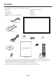
Contents Your new MultiSync LCD monitor box* should contain the following: • LCD monitor • Screw for clamp (M4 x 10) x 2 • Power Cord*1 • CD-ROM • Video Signal Cable • Eyebolt x 2 • Setup Manual • Washer x 2 • Wireless Remote Control and AAA Batteries • Hanger bolt x 8 • Clamp 15-pin mini D-SUB male to DVI-A DVI-D to DVI-D cable Screw for clamp (M4 x 10) x 2 Washer x 2 Clamp Power Cord*1 Hanger bolt x 8 Setup Manual CD-ROM Eyebolt x 2 Setup Manual Wireless Remote Control and A
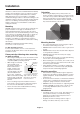
This device cannot be used or installed without the Tabletop Stand or other mounting accessory for support. For proper installation it is strongly recommended to use a trained, NEC authorized service person. Failure to follow NEC standard mounting procedures could result in damage to the equipment or injury to the user or installer. Product warranty does not cover damage caused by improper installation. Failure to follow these recommendations could result in voiding the warranty.
Attaching Mounting Accessories 3. Ventilation Requirements The display is designed for use with the VESA mounting system. When mounting in an enclosed space or recessed area, leave adequate room between the monitor and the enclosure to allow heat to disperse, as shown below. In order to aid in mounting, a lifting device must be used in conjunction with the attachable eyebolts. 1. Attach eyebolts for mounting This model is equipped with attachable eyebolts to aid in mounting.
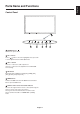
Control Panel 1 POWER button ( ) Switches the power on/off. 2 CH +/- button Acts as button to move the highlighted area up or down to select adjustment items within OSD menu. 3 VOL +/- button Increases or decreases audio output level. Increases or decreases the adjustment level within OSD menu settings. 4 SEL button Enter Input Source OSD menu, [DVI], [PC], [HDMI], [AV1], [AV2], [S-Video] and [Component]. 5 MENU button Activates the OSD menu when the OSD menu is turned-off. Move to previous OSD menu.
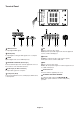
Terminal Panel 1 HDMI connector 7 AV1 To input digital HDMI signals. AV1: For composite video signal. Audio L, R: To input audio signal from external equipment such as a VCR or DVD player. 2 DVI IN (DVI-I) To input digital or analogue RGB signals from a computer. 8 S-Video 3 SPDIF Optical digital audio out for HDMI input only. S-Video: To input the S-video (Y/C separate signal). Audio input connects to AV2’s Audio L/R.
10 PC button Selects input source of DVI connector. 11 MENU button Turns on the menu mode. 12 EXIT button Turns off the menu mode. 13 CH +/- button button to move the highlighted area up or down Acts as to select adjustment items within OSD menu. 14 VOL +/- button Increases or decreases audio output level. Increases or decreases the adjustment level within OSD menu settings. 15 ENTER button Makes selection.
Setup 1. Determine the installation location NEC recommends the following battery use: CAUTION: Installing your LCD display must be done by a qualified technician. Contact your dealer for more information. • Place “AAA” size batteries matching the (+) and (-) signs on each battery to the (+) and (-) signs of the battery compartment. • Do not mix battery brands. • Do not combine new and old batteries.
When connected with a computer, switch on the power of the computer first. 6. Operate the attached external equipment Display the signal from the desired input source. 7. Adjust the sound Make volume adjustments when required. 8. Adjust the screen (See page 18) Make adjustments of the screen display position when necessary. 9. Adjust the image (See page 18) Make adjustments such as brightness or contrast when required. 10.
Connections Before making connections: * First turn off the power of all the attached equipment and make connections. * Refer to the user manual included with each separate piece of equipment. Connecting a Personal Computer Connecting your computer to your LCD monitor will enable you to display your computer’s screen image. Some video cards and a pixel clock over 162MHz may not display an image correctly. Your LCD monitor displays proper image by adjusting the factory preset timing signal automatically.
English Connecting a DVD Player with component out Connecting your DVD player to your LCD monitor will enable you to display DVD video. Refer to your DVD player user’s manual for more information. Connect the LCD Monitor to a DVD Player To connect the Component connector (RCA) on the LCD monitor, use an RCA connector cable (sold separately).
Connecting a DVD Player with HDMI out Connecting your DVD player to your LCD monitor will enable you to display DVD video. Refer to your DVD player user’s manual for more information. Connect the LCD Monitor to a DVD Player • Please use an HDMI cable with HDMI logo. • It may take a moment for the signal to appear. • PC-DVI signals are not supported. LCD monitor To HDMI output HDMI connector Connecting to a Stereo Amplifier You can connect your stereo amplifier to your LCD monitor.
English Basic Operation Power ON and OFF Modes The LCD monitor power indicator will turn green while powered on and will turn red while powered off.
Power Indicator Picture Size Mode DVI, PC Status Indicator Light Power ON Green Power OFF (Standby)* Power consumption under 1W Red Power Save Power consumption under 15W Red blinking Not connected Green blinking 16:9 1:1 4:3 HDMI, AV1, AV2, S-Video, Component 16:9 Panorama Aspect ratio of image * When in Power OFF (Standby) mode, RS-232C control do not function.
English OSD (On-Screen-Display) Controls NOTE: Some functions may not be available depending on the model or optional equipment. Main Menu Item Main Menu Icons Key Guide Press MENU button to show OSD menu. Press UP and DOWN to select the main menu. Press Right button to enter the sub menu. Press EXIT to exit menu. Press MENU button to show OSD menu. Press CH+ and CHbuttons to select the main menu. Press VOL+ button to enter the sub menu. Press MENU button to back to previous menu.
OSD Picture Setting Picture Mode User Store last value at User setting. Dynamic Selection of the picture appearance. Standard Movie Mild User Brightness Adjust the brightness. Contrast Adjust the Contrast. Color (AV1/AV2/S-Video/Component) Adjust the Color. Tint (AV1/AV2/S-Video/Component) Adjust the Tint. Sharpness Adjust the Sharpness. Phase (Component) Adjust the Phase Color Temp User (PC, DVI, HDMI) This Function is for user setting of color Temp.
Mode User This function use setting Equalizer value. Standard Selection of preset Sound mode (Equalizer). Music Movie Speech Volume Adjust the sound volume level. Balance Tuning the sound balance between left and right. Equalizer 10 KHz The value of 5 Band equalizer are preset. 3 KHz These values are changed by user with user mode setting.
Advanced Dimming Auto Dimming Enable/Disalbe Auto Dimming control by Abient Light sensor. Dim Level Display current Dim Level. MAX Dim Ambient Adjusts detected light ambient to set the maximun dimming. MIN Dim Ambient Adjusts detected light ambient to set the minimun dimming. Ambient Display current detected light ambient level by Lux unit. Heat Control Fan Control Controls fan driving option by temperature sensor / force on/ force off.
This LCD monitor can be controlled by connecting a personal computer with a RS-232C terminal. Functions that can be controlled by a personal computer are: • Power ON or OFF • Switching between input signals LCD Monitor Connection LCD Monitor + PC PC (Out) RS-232C (IN) terminal RS-232C Cable NOTE: If your PC (IBM or IBM compatible) is equipped only with a 25-pin serial port connector, a 25-pin serial port adapter is required. Contact your dealer for details.
Features Color Control Systems: Allows you to adjust the colors on your screen and customize the color accuracy of your monitor to a variety of standards. OSD (On-Screen-Display) Controls: Allow you to quickly and easily adjust all elements of your screen image via simple to use on-screen menus.
No picture • The signal cable should be completely connected to the display card/computer. • The display card should be completely seated in its slot. • Front Power Switch and computer power switch should be in the ON position. • Check to make sure that a supported mode has been selected on the display card or system being used. (Please consult display card or system manual to change graphics mode.) Image of component signal is greenish • Check to see if the DVD/HD input connector is selected.
Specifications Product Specifications LCD Module Pixel Pitch: Resolution: Color: Brightness: Contrast Ratio: Viewing Angle: Design View Distance: Frequency Horizontal: Vertical: 81.6"/207 cm diagonal 0.744 mm 1920 x 1080 dots Over 16 million colors (depending on video card used) 600 cd/m2 (Typ.) (LCD8205)/450 cd/m2 (Typ.) (LCD8205-P) 2000:1 89° (typ) @ CR>10 (LCD8205)/85° (typ) @ CR>10 (LCD8205-P) 1500 mm 15.625/15.734 kHz, 31.5 kHz - 91.1 kHz (Analog Input) 31.5 kHz - 91.1 kHz (Digital Input) 50.0 - 85.
English Pin Assignment 1) S-VIDEO input: VIDEO Pin No Name 1 GND 2 GND 3 Y (Luminance) 4 C (Chroma) 2) Digital/Analog RGB input: DVI-I Pin - Assignment of DVI connector: 1 TX2- 9 TX1- 17 2 TX2+ 10 TX1+ 18 TX0TX0+ 3 Shield (TX2 / TX4) 11 Shield (TX1 / TX3) 19 Shield (TX0 / TX5) 4 NC 12 NC 20 NC 5 NC 13 NC 21 NC 6 DDC-Serial Clock 14 +5V power 22 Shield (TXC) 7 DDC-Serial Data 15 Ground 23 TXC+ 8 NC 16 Hot plug detect 24 TXC- 3) RS-232C input Pin No N
Manufacturer’s Recycling and Energy Information NEC DISPLAY SOLUTIONS is strongly committed to environmental protection and sees recycling as one of the company’s top priorities in trying to minimize the burden placed on the environment. We are engaged in developing environmentallyfriendly products, and always strive to help define and comply with the latest independent standards from agencies such as ISO (International Organisation for Standardization) and TCO (Swedish Trades Union).