INSTALLATION & MAINTENANCE GUIDE MD212MC MD213MC MD213MG
Index Warning, Caution ........................................................................................................................ English-1 Registration Information .............................................................................................................. English-2 Recommended use ..................................................................................................................... English-3 Contents ...........................................................
TO PREVENT FIRE OR SHOCK HAZARDS, DO NOT EXPOSE THIS UNIT TO RAIN OR MOISTURE. ALSO, DO NOT USE THIS UNIT'S POLARIZED PLUG WITH AN EXTENSION CORD RECEPTACLE OR OTHER OUTLETS UNLESS THE PRONGS CAN BE FULLY INSERTED. REFRAIN FROM OPENING THE CABINET AS THERE ARE HIGH VOLTAGE COMPONENTS INSIDE. REFER SERVICING TO QUALIFIED SERVICE PERSONNEL. CAUTION TO REDUCE THE RISK OF ELECTRIC SHOCK, MAKE SURE POWER CORD IS UNPLUGGED FROM WALL SOCKET.
Registration Information Declaration Declaration of the Manufacturer Means of Conformity NEC Display Solutions Europe GmbH declares that this product is in conformity with the essential requirements and provisions of the Council Directive 93/42/EEC and conform to the applicable clauses of the following standards: Device Classification: Class I, non-measuring function Applicable Rules: Annex IX, Rules 1.4 (Section 1) and 1.1 (Section 3) Product Name: MD212MC/MD213MC 21.
English Recommended use Safety Precautions and Maintenance FOR OPTIMUM PERFORMANCE, PLEASE NOTE THE FOLLOWING WHEN SETTING UP AND USING THE LCD COLOR MONITOR: • DO NOT OPEN THE MONITOR. There are no user serviceable parts inside and opening or removing covers may expose you to dangerous shock hazards or other risks. Refer all servicing to qualified service personnel. • Do not spill any liquids into the cabinet or use your monitor near water.
CORRECT PLACEMENT AND ADJUSTMENT OF THE MONITOR CAN REDUCE EYE, SHOULDER AND NECK FATIGUE. CHECK THE FOLLOWING WHEN YOU POSITION THE MONITOR: • For optimum performance, allow 20 minutes for warm-up. • Adjust the monitor height so that the top of the screen is at or slightly below eye level. Your eyes should look slightly downward when viewing the middle of the screen. • Position your monitor no closer than 40 cm and no further away than 70 cm from your eyes. The optimal distance is 50 cm.
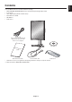
English Contents Your new NEC monitor box* should contain the following: • MD212MC/MD213MC/MD213MG monitor with tilt/swivel/pivot/height adjust stand • Power Cord • Video Signal Cable (DVI-D to DVI-D cable)*1 • Quick Reference Guide • CD-ROM x 2 • Cable Cover Power Cord (Type of power cord included will depend on the where the LCD monitor is to be shipped) CD-ROM x 2 Quick R eferenc e Guide Quick Reference Guide * DVI-D to DVI-D cable Cable Cover Remember to save your original box and pa
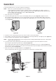
Quick Start To attach the LCD monitor to your system, follow these instructions: NOTE: Make sure to read “Recommended Use” before installation. In order to display the maximum resolution, a display controller is required which can output a resolution of 1200 x 1600 (in portrait mode) or 1600 x 1200 (in landscape mode) for MD212MC and 1536 x 2048 (in portrait mode) or 2048 x 1536 (in landscape mode) for MD213MC/MD213MG. We recommend using a digital input. 1. Turn off the power to your computer. 2.
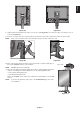
English Figure C.4 Figure C.3 8. Hold all cables firmly and place the cable cover onto the stand (Figure D.1). To remove the cable cover, lift the cover off as shown in Figure D.2. 9. Connect one end of the power cord to the AC inlet on the back of the monitor and the other end to the power outlet. NOTE: Please refer to Caution section of this manual for proper selection of AC power cord. Figure D.1 Figure D.2 10.
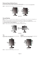
Raise and Lower Monitor Screen The monitor may be raised or lowered in either Portrait or Landscape mode. To raise or lower screen, place hands on each side of the monitor and lift or lower to the desired height (Figure RL.1). NOTE: Handle with care when raising or lowering the monitor screen. Figure RL.1 Screen Rotation Before rotating, the screen must be raised to the highest level to avoid knocking the screen on the desk or pinching with your fingers.
English Flexible Arm Installation This LCD monitor is designed for use with a flexible arm. To prepare the monitor for alternate mounting purposes: • Refer to instructions included with the flexible arm for detailed instructions. • To fulfill the safety requirements the monitor must be mounted to an arm, which guaranties the necessary stability under consideration of the weight of the monitor. Remove Monitor Stand 1. Remove the cable cover. 2. Disconnect all cables. 3.
Controls The OSD (On-Screen Display) control buttons are located on the back of the monitor: To access OSD menu, press the EXIT button. To change signal input, press the SELECT button. NOTE: OSD must be closed in order to change signal input. 7 8 9 6 5 4 3 10 2 1 1 LED Indicates that the power is on. 2 RESET Resets the OSD back to factory settings.
English Luminance/Contrast Controls LUMINANCE Adjusts the overall image and background screen luminance. When LUMINANCE is adjusting the numerical values blinks. AUTO CONTRAST (Analog input only) Adjusts the image displayed for non-standard video inputs. BLACK LEVEL (Analog input only) Adjust the black level manually. Auto Adjust (Analog input only) Automatically adjusts the Image Position and V.Size (H.Size) settings and Fine settings.
EXPANSION Sets the zoom method. FULL: The image is expanded to 1200 x 1600 (in portrait mode) or 1600 x 1200 (in landscape mode) for MD212MC and 1536 x 2048 (in portrait mode) or 2048 x 1536 (in landscape mode) for MD213MC/MD213MG, regardless of the resolution. ASPECT: The image is expanded without changing the aspect ratio. OFF: The image is not expanded. CUSTOM: Refer to the ADVANCED OSD Controls menu section of the user’s manual for detailed instructions.
This function allows the monitor to enter into a power saving mode after a period of inactivity. The OFF MODE has two settings. OFF: Monitor does not go into power save mode when the input signal is lost. STANDARD: Monitor enters power save mode automatically when the input signal is lost. UNIFORMITY This function electronically compensates for the slight variations in the white uniformity level, as well as for deviations in color that may occur throughout the display area of the screen.
FACTORY PRESET Selecting Factory Preset allows you to reset all OSD control settings (LUMINANCE, BLACK LEVEL, IMAGE CONTROL, COLOR CONTROL SYSTEM, SHARPNESS, OFF MODE, OSD LEFT/RIGHT, OSD UP/DOWN, OSD TURN OFF) back to the factory settings. Individual settings can be reset by highlighting the control to be reset and pressing the RESET button.
• When OSD is off, push the “RESET” and “EXIT” button at the same time. • You will see the Advanced menu. This menu is larger than the normal OSD. • Push the “EXIT” button. To make an adjustment, ensure that the tag is highlighted, then press “SELECT”. To move to another tag, press “EXIT”, then press “Left” or “Right” to highlight another tag. Tag1 Tag2 Luminance Adjusts the overall image and screen background luminance.
Tag3 Auto Adjust (Analog input only) Automatically adjusts the Image Position and V.Size (H.Size) settings and Fine settings. Press “SELECT” to activate Auto Adjustment. Signal Adjust (Analog input only) Determines when the auto adjustment is activated automatically. The choices are “SIMPLE” and “FULL”. Press “Left” or “Right” to select. V.Size (H.
(Available in Custom Expansion mode only) V.ZOOM (Available in Custom Expansion mode only) ZOOM POS. (Available in Custom Expansion mode only) The image is expanded from 1 to 3 times in the horizontal (H. EXPANSION) direction by 0.01 increments. The image is expanded from 1 to 3 times in the vertical (V. EXPANSION) direction by 0.01 increments. Sets the point from which the screen will be expanded when either H.ZOOM or V.ZOOM is selected as the expansion method. Options are CENTER and LEFT TOP.
Tag7 Sharpness This is a digital capability for keeping a crisp image at all signal timings. It continuously adjusts to maintain as distinct or as soft an image as you prefer and is set independently according to different timings. Press “Left” or “Right” to adjust. DVI Selection This function selects the DVI input mode. When the DVI selection has been changed, you must restart your computer. Press “Left” or “Right” to select. AUTO: By using the DVI-D to DVI-D cable, the DVI SECTION is DIGITAL.
This control completely locks out access to all OSD control functions. When attempting to activate OSD controls while in the Lock Out mode, a screen will appear indicating the OSD controls are locked out. There are three types of OSD LOCK OUT: OSD LOCK OUT with no control: To activate the OSD Lock Out function, press SELECT, then “Right” button and hold down simultaneously. To deactivate the OSD Lock Out, press SELECT, then “Right” button and hold down simultaneously while in the OSD menu.
TagA TagB Input Setting (Analog input only) Video Band Width: Reduce the visual “noise” level of the input signal. The video band width settings range from 0-7, with 0 having no correction and 7 having the most noise correction. Press “Left” or “Right” to select. Sync Threshold: Adjusts the slice level of a synchronization signal. Press “SELECT” to move the adjustment menu. Adjusts the sensitivity of the separate or composite input signals.
Before proper calibration can be performed, display should warm-up for a minimum of 30 minutes. If trying to start calibration before the monitor is warmed-up, a warning will appear on the screen (Figure 1). KEY MAP UP/DOWN: LEFT/RIGHT: SELECT: EXIT: Changes from setting to setting Changes the setting selection (ie...
6. Press SELECT to start the calibration. Front sensor calibration may take several minutes depending on user setting. 7. After the CALIBRATION SUCCEEDED message appears (Figure 6), press SELECT. To end the calibration mode, press “EXIT”. Figure 6 Copy Calibration 1. To show the CALIBRATION menu, plug-in the USB sensor to the sensor port (Figure 7) or select the CALIBRATION in the advanced menu (page 20). USB Sensor Sensor port is located at the back of the monitor.
6. After copying the Display A information, the target luminance and target chromaticity coordinates will be stored and displayed in the OSD of Display B. The target value is not adjustable (Figure 11). 7. Remove USB sensor from source Display A and place in the center of Display B (Figure 8). Figure 11 8. Press SELECT to start the copy calibration. Copy calibration may take several minutes depending on the user settings. 9.
DICOM Measurement 1. To show the CALIBRATION menu, select the CALIBRATION in the advanced menu (page 20). 2. Select DICOM MEASURE in the Mode selection (Figure 17). Figure 17 Figure 18 3. Select the Color setting in COLOR*2 selection and Gamma setting in GAMMA selection. *2 MD213MG does not have COLOR selection. 4. Press SELECT to start the DICOM MEASUREMENT. This may take several minutes depending on user setting. 5. After the DICOM MEASURED RESULT message appears (Figure 18), press SELECT.
Monitor Specifications MD212MC Monitor Notes LCD Module Diagonal: 54.0 cm/21.3 inches Viewable Image Size: 54.0 cm/21.3 inches Native Resolution (Pixel Count): 1200 x 1600 (Portrait) 1600 x 1200 (Landscape) Input Signal Video: ANALOG 0.7 Vp-p/75 Ohms Sync: Separate sync.TTL Level Horizontal sync. Positive/Negative Vertical sync. Positive/Negative Composite sync.
Specifications - MD213MC Monitor Specifications MD213MC Monitor Notes LCD Module Diagonal: 54.0 cm/21.3 inches Viewable Image Size: 54.0 cm/21.3 inches Native Resolution (Pixel Count): 1536 x 2048 (Portrait) 2048 x 1536 (Landscape) Input Signal Video: ANALOG 0.7 Vp-p/75 Ohms Sync: Separate sync.TTL Level Horizontal sync. Positive/Negative Vertical sync. Positive/Negative Composite sync. Positive/Negative Display Colors 16,777,216 Synchronization Range 31.5 kHz to 95.4 kHz (Digital) 31.5 kHz to 93.
Monitor Specifications MD213MG Monitor Notes LCD Module Diagonal: 54.0 cm/21.3 inches Viewable Image Size: 54.0 cm/21.3 inches Native Resolution (Pixel Count): 1536 x 2048 (Portrait) 2048 x 1536 (Landscape) Input Signal Video: ANALOG 0.7 Vp-p/75 Ohms Sync: Separate sync.TTL Level Horizontal sync. Positive/Negative Vertical sync. Positive/Negative Composite sync. Positive/Negative Display Tones 10bit: 1024 (10bit) shades of gray from a pallet of 12241 (13.
Features DVI-I: The integrated interface ratified by the Digital Display Working Group (DDWG) that allows both digital and analog connectors off of one port. The “I” stands for integration for both digital and analog, The digital portion is DVI-based. DVI-D: The digital-only subset of DVI ratified by the Digital Display Working Group (DDWG) for digital connections between computers and displays. As a digital-only connector, analog support is not provided off a DVI-D connector.
No picture • The signal cable should be completely connected to the display card/computer. • The display card should be completely seated in its slot. • Power Switch and computer power switch should be in the ON position. • Check to make sure that a supported mode has been selected on the display card or system being used. (Please consult display card or system manual to change graphics mode.) • Check the monitor and your display card with respect to compatibility and recommended settings.
Manufacturer’s Recycling and Energy Information NEC DISPLAY SOLUTIONS is strongly committed to environmental protection and sees recycling as one of the company’s top priorities in trying to minimize the burden placed on the environment. We are engaged in developing environmentallyfriendly products, and always strive to help define and comply with the latest independent standards from agencies such as ISO (International Organisation for Standardization) and TCO (Swedish Trades Union).