本書は製品とともに大切に保管してください Keep this manual carefully. N8103-102 増設バッテリ ユーザーズガイド Additional DAC Battery User's Guide • 製品をご使用になる前に必ず本書をお読みください。 本書は熟読の上、大切に保管してください。 • Make sure you read this manual before using the product. After reading this manual carefully, store it in a safe place.
商標について Microsoft とそのロゴおよび、Windows、MS、MS-DOS は米国 Microsoft 社の米国およびその他の国 における登録商標です。 TM PromiseTechnology, Inc.とそのロゴおよび、SuperTrak、SuperBuild Utility、Web-based Promise Array Management(WebPAM)は、米国 Promise 社の登録商標です。 Trademarks Microsoft, its logo, Windows, Windows Server and MS-DOS are worldwide registered trademarks of Microsoft Corporation of the U.S.A. Promise Technology, Inc.
まえがき Preface このたびは、N8103-102 増設バッテリ(以降「本製品」と呼ぶ)をお買い上げいただきまこ とにありがとうございます。本書は、本製品を正しく、安全に設置・使用するための手引 きです。本製品を取り扱う前に必ずお読みください。また、本製品を使用する上でわから ないこと、不具合が起きたときにもぜひご利用ください。本書は、必要な時にすぐに参照 できるように必ずお手元に保管してください。 本製品を取り付ける N8103-101 ディスクアレイコントローラ(SATA2)の取り扱いについて は、N8103-101 ディスクアレイコントローラ(SATA2)添付のユーザーズガイドをご覧くだ さい。 また、本製品を取り扱う前に「使用上のご注意」を必ずお読みください。 なお、本書は和英併記となっております。日本語での説明は i ページから 20 ページを、英 語での説明は i ページから xviii ページおよび、21 ページから 38 ページを参照してくださ い。 Congratulations for your purchase of the N8103-102 Additional DAC Bat
ii このユーザーズガイドは、必要なときすぐに参照できるよう、お手元に置いておくようにしてください。 「使用上のご注意」を必ずお読みください。 Keep this User's Guide at hand for quick reference at anytime necessary. Be sure to read this section carefully. 使用上のご注意 ∼必ずお読みください∼ NOTES ON USE - Always read the Notes 本製品を安全に正しくご使用になるために必要な情報が記載されています。 The following includes information necessary for proper and safe operation of the product.
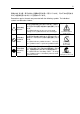
iii 危険に対する注意・表示は次の3種類の記号を使って表しています。それぞれの記号は次 のような意味を持つものとして定義されています。 Precautions against hazards are presented with the following symbols. The individual symbols are defined as follows: 注意の喚起 Attention 行為の禁止 Prohibited Action 行為の強制 Mandatory Action この記号は危険が発生するおそれがあることを表し ます。記号の中の絵表示は危険の内容を図案化したも のです。 This symbol indicates the presence of a hazard. An image in the symbol illustrates the hazard type. この記号は行為の禁止を表します。記号の中や近くの 絵表示は、してはならない行為の内容を図案化したも のです。 This symbol indicates prohibited actions.
iv 本書で使用する記号とその内容 Symbols Used in This Manual and Warning Labels 注意の喚起 Attentions 特定しない一般的な注意・警告を示します。 Indicates a general notice or warning that cannot be specifically identified. 感電のおそれがあることを示します。 Indicates that improper use may cause an electric shock. 高温による障害を負うおそれがあることを示します。 Indicates that improper use may cause personal injury. 発煙または発火のおそれがあることを示します。 Indicates that improper use may cause fumes or fire.
v 安全上のご注意 Safety Indications 本製品を安全にお使いいただくために、ここで説明する注意事項をよく読んでご理解して いただき、安全にご活用ください。記号の説明については巻頭の『安全にかかわる表示に ついて』の説明を参照してください。 This section provides notes on using your product safely. Read this section carefully to ensure proper and safe use of the product. For symbols, see "SAFETY INDICATIONS" provided earlier. <全般的な注意事項> General WARNING 人命に関わる業務や高度な信頼性を必要とする業務には使用しない Do not use the product in life-critical applications or applications requiring high reliability.
vi CAUTION 装置内に水や異物を入れない Keep water or foreign matter away from the server. 装置内に水などの液体、ピンやクリップなどの異物を入れないでください。火災や 感電、故障の原因となります。もし入ってしまったときは、すぐに本体装置の電源 をOFFにして電源コードをACコンセントから抜いてください。分解しないで販売店 または保守サービス会社に連絡してください。 Do not let any form of liquid (water etc.) or foreign matter (e.g., pins or paper clips) enter the server. Failure to follow this warning may cause an electric shock, a fire, or a failure of the server.
vii <電源・電源コードに関する注意事項> Power Supply and Power Cord Use CAUTION 電源がONのまま取り付け・取り外しをしない Disconnect the power cord(s) before installing or removing the product in/from the server. 本体装置への取り付け・取り外しの際や、周辺機器との接続の際は必ず主電源に接 続している電源コードをACコンセントから抜いてください。電源コードがACコンセ ントに接続されたまま取り付け・取り外しや接続をすると感電するおそれがありま す。 Make sure to power off the server and disconnect the power cord(s) from a power outlet before installing/removing the product in/from the server, or connecting with the peripheral devices.
viii <設置・移動・保管・接続に関する注意事項> Installation, Relocation, Storage, and Connection CAUTION プラグを差し込んだままインタフェースケーブルの取り付けや取り外しをしない Do not connect any interface cable with the power cord of the server plugged to a power source. インタフェースケーブルの取り付け/取り外しは本体装置の電源コードをコンセン トから抜いて行ってください。たとえ電源をOFFにしても電源コードを接続したま まケーブルやコネクタに触ると感電したり、ショートによる火災を起こしたりする ことがあります。 Make sure to power off the server and unplug the power cord from a power outlet before connecting/disconnecting any interface cable to/from the server.
ix CAUTION 腐食性ガスの存在する環境で使用または保管しない Do not use or store the product in the place where corrosive gases exist. 腐食性ガス(二酸化硫黄、硫化水素、二酸化窒素、塩素、アンモニア、オゾンなど) の存在する環境に設置し、使用しないでください。 また、ほこりや空気中に腐食を促進する成分(塩化ナトリウムや硫黄など)や導電 性の金属などが含まれている環境へも設置しないでください。装置内部のプリント 板が腐食し、故障および発煙・発火の原因となるおそれがあります。もしご使用の 環境で上記の疑いがある場合は、販売店または保守サービス会社にご相談ください。 Make sure not to locate or use the server in the place where corrosive gases (sulfur dioxide, hydrogen sulfide, nitrogen dioxide, chlorine, ammonia, ozone, etc) exist.
x <お手入れに関する注意事項> Cleaning and Working with the Product WARNING 自分で分解・修理・改造はしない Do not disassemble, repair, or alter the server. 本製品の分解や、修理・改造は絶対にしないでください。装置が正常に動作しなく なるばかりでなく、感電や火災の危険があります。 Never attempt to disassemble, repair, or alter the product on any occasion. Failure to follow this instruction may cause an electric shock or fire as well as malfunctions of the product. プラグを差し込んだまま取り扱わない Disconnect the power plug before accessing inside the server.
xi <運用中の注意事項> During Operation CAUTION 雷がなったら触らない Avoid contact with the server during thunderstorms. 雷が鳴りだしたら、本製品内蔵の本体装置には、触れないでください。感電するお それがあります。 Disconnect the power plug from the outlet when a thunderstorm is approaching. If it starts thundering before you disconnect the power plug, do not touch any part of the server containing the product. Failure to follow this warning may cause an electric shock. ペットを近づけない Keep animals away from the server.
xii 警告ラベルについて Warning Labels 本製品には警告ラベルが貼り付けられています。これは本製品を操作する際に考えられる 危険性を常にお客様に意識していただくためのものです(ラベルをはがしたり、汚したり しないでください) 。もしこのラベルが貼り付けられていない、はがれかかっている、汚れ ているなどして判読できないときはご購入された販売店にご連絡ください。 The warning label is attached to the product with possible danger or their vicinity in your product to inform the user that a hazardous situation may arise when operating the product. (Do not intentionally remove or damage any of the labels.
xiii 使用上のご注意 ∼装置を正しく動作させるために∼ Notes on Use - for correct operation of BBU 本製品を使用するときに注意していただきたいことを次に示します。これらの注意を無視 して、本製品を使用した場合、資産(データやその他の装置)が破壊されるおそれがあります ので必ずお守りください。 本製品は N8103-101 ディスクアレイコントローラ(SATA2)専用の増設バッテリで す。その他のディスクアレイコントローラには接続できません。 本製品は大変デリケートな電子装置です。本製品を取り扱う前に、本体装置の金 属フレーム部分などに触れて身体の静電気を逃がしてください。 本製品を落としたり、ぶつけたりしないでください。 本製品のリサイクルと廃棄に関しては、本章の「リサイクル・廃棄について」を 参照して下さい。 Note the following when you use the BBU.
xiv 本書について This Manual 本書は、Windows などのオペレーティングシステムやキーボード、マウスといった一般的 な入出力装置などの基本的な取り扱いについて十分な知識を持ったユーザを対象として記 載されています。 The guide is intended for persons who are familiar with operating systems including Windows and fundamental operations of general-purpose I/O devices including the keyboard and mouse. <本書の記号について> Text Conventions 本書の中には安全に関わる注意記号の他に次の3種類の記号を使用しています。それぞれ の記号は次のような意味をもつものとして定義されています。 The following conventions are used throughout this User's Guide.
xv 梱包箱の中身について In the Package 梱包箱の中には本製品以外に色々な添付品が同梱されています。本製品に添付の構成品表 を参照し、全ての添付品が揃っていることを確認してください。万一、足りないものや損 傷しているものがあった場合には、本製品をご購入された販売店にご連絡ください。 The carton contains various accessories, as well as the product itself. See the packing list to make sure that you have everything and that individual components are not damaged. If you find any component missing or damaged, contact your sales agent.
xvi 第三者への譲渡について Transfer to Third Party 本製品を第三者に譲渡(または売却)する時には、必ず本書を含む全ての添付品をあわせ て譲渡(または売却)してください。 Make sure to provide this manual along with the product to a third party.
xvii 製品寿命について Life of BBU 本製品にはバックアップ用のバッテリが付いています。バッテリの寿命は使用環境や運用 条件により異なりますが、約 2 年間となっております。 本製品の設置から約 2 年後(設置時期は本体装置および本製品に貼り付けのバッテリラベル に記載)を目安に交換してください。交換については、本製品をご購入された販売店もしく はご契約されている NEC 保守サービス会社へご相談ください。 The BBU is equipped with a backup battery. The life of the battery is about 2 years while it varies depending on the use environment and operating conditions.
xviii リサイクル・廃棄について Recycle and Disposal 本製品のバッテリパックにはリチウムイオンバッテリが搭載されており、リサイクルが可 能です。貴重な資源を再利用するため、本製品をご購入された販売店もしくはご契約され ている NEC 保守サービス会社までお問い合わせいただくか、最寄りのリサイクル協力店 にお持ちください。バッテリパックの取り外し方法は、「第 3 章 運用・保守」の「4. バッ テリパックの交換手順」従ってください。 その他部材の破棄については、各自治体の廃棄ルールに従って分別廃棄してください。詳 しくは各自治体にお問い合わせいただくか、本製品をご購入された販売店もしくはご契約 されている NEC 保守サービス会社にご相談ください。 バッテリパックは「第 3 章 運用・保守」を参照して取り扱いに十分注意してください。 The battery pack of the BBU is equipped with lithium ion battery which is recyclable.
xix 目 次 まえがき Preface ......................................................................................................................... i 使用上のご注意 ∼必ずお読みください ∼ NOTES ON USE - Always read the Notes - .............................................................. ii 本書で使用する記号とその内容 Symbols Used in This Manual and Warning Labels ................ iv 安全上のご注意 Safety Indications.............................................................................................. v 警告ラベルについて Warning Labels .........
xx Contents Chapter 1 Overview ........................................................................................................... 21 1. Characteristics of BBU ............................................................................................................... 21 2. Specification ............................................................................................................................... 22 3. Installation Flow ...........................................................
第 1 章 概要 N8103-102 増設バッテリ(以降「本製品」と呼ぶ)を初めてお使いになる場合は、この章か らお読みください。 ここでは、本製品の特徴、構成およびバッテリ増設作業の概要について説明します。 1.
2 2. 仕様 項 目 最大データバックアップ時間 外形寸法 フルハイト PCI ブラ ケット使用時 ロープロファイル PCI ブラケット使用時 質量 動作電圧 消費電力 動作環境 温度 湿度 保管環境 温度 湿度 寿命(バッテリパック部) 仕 様 72 時間 121(幅)×120(奥行)X22(高)mm 備 考 満充電時 バッテリケーブルを除く 81(幅)×120(奥行)X22(高)mm 約 0.10(kg) 3.7(V)∼ 1.
3 3. 取り付け作業の流れ 本製品を取り付ける作業の流れは以下の通りです。詳しい作業内容については、それぞれ 対応する章をご覧になってください。 開始 製品・添付品の確認 注意事項の確認 バッテリの取り付け 接続確認・設定 終了 第1章 製品および添付品の確認、バッテリ取 り付け時の注意について説明します。 第2章 「1. 取り付け手順」 バッテリの取り付け方法について説明 します。 第2章 「2.
4 4. 梱包箱の中身を確認する 梱包箱には次のものが入っています。作業を開始する前に確認してください。 項番 1 2 3 4 5 品 名 増設バッテリ ユーザーズガイド バッテリラベル ロープロファイル PCI ブラケット 保証書 数量 1 1 1 1 1 備 考 本製品 本書 保証書は記載内容を確認の上、大切に保管してください。 以下のものが梱包箱に入っています。 ユーザーズガイド (本書) 増設バッテリ Set up Date Y ロープロファイル PCI ブラケット .
5 5.
6 本製品裏面 添付品 8 9 Set up Date Y .
7 6. 注意事項 本製品のご使用する前に、以下の注意事項をご覧ください。 6-1. 取り付け時の注意事項 本製品を、本体装置の筐体などの金属部の上においたり、ぬれた手で持ったりし ないでください。バッテリがショートする恐れがあります。 本製品を取り付けるために、本体装置の PCI スロットを 1 スロット使用します。 取り付ける前に未使用の PCI スロットがあることを確認してください。 6-2.
8
第 2 章 本製品の取り付け ここでは、本製品の取り付け方法について説明します。 1. 取り付け手順 以下の手順に従って、本製品をディスクアレイコントローラに取り付けてください。 作業の前に、ディスクアレイコントローラ添付のユーザーズガイドおよび本体 装置のユーザーズガイドをよくご覧になってください。 1-1. PCI スロットの選択 本製品は PCI ブラケットの取り付け位置を変更することで、PCI/PCI-X スロットと PCI-Express スロットのどちらのスロットにも実装することができます。未使用のスロッ トの状況に合わせて、実装する PCI スロットを選択してください。 なお、ロープロファイル PCI スロットに実装する場合は、次の項「1-2. ブラケットの選択・ 取り付け」もご覧になり、PCI ブラケットの交換も同時に行ってください。 PCI ブラケットは、出荷時 PCI-Express スロットに合わせて取り付けられています。 PCI/PCI-X スロットに実装する場合は、次の手順で変更してください。 1.
10 1-2. ブラケットの選択・取り付け 本製品にはフルハイト PCI ブラケットが取り付けられています。ロープロファイルに対応 した PCI スロットに本製品を取り付ける場合は、添付のロープロファイル PCI ブラケット に交換する必要があります。 1. フルハイト PCI ブラケットと本製品を固定しているネジ(2 本)を取り外します 2. フルハイト PCI ブラケットを取り外します。 3. ロープロファイル PCI ブラケットを取り付けます。 4. ロープロファイル PCI ブラケットを手順 1 で取り外したネジ(2 本)で固定します。 フルハイト PCI ブラケット ロープロファイル PCI ブラケット 1-3. バッテリラベルの貼り付け 本製品に添付されているバッテリラベルに、本製品を実装した日付(年月)を記入し、PCI ブ ラケットに貼り付けてください。 日付(年月)を記入 Set up Date Y 例)Y 2006.M 5 .
11 1-4. サイドカバーの取り外し 本体装置のユーザーズガイドを参照しながら、サイドカバーを取り外します。 なお、サイドカバーを取り外す時には、本体装置の電源を OFF にして、電源ユニットに接 続しているすべての電源コードをコンセントから取り外してから実施してください。 1-5. 本製品の取り付け 本製品をディスクアレイコントローラおよび本体装置に取り付けます。 1. 未使用の PCI スロットの増設スロットカバーとネジおよびディスクアレイコント ローラに接続されたケーブルを外します。 2.
12 3. 本製品およびディスクアレイコントローラを PCI スロットに実装し、取り外した ネジでしっかりと固定します。 ディスクアレイコントローラ ネジ 本製品 バッテリケーブル 本製品を取り付けるために、本体装置のPCIスロットを1スロット使用します。 取り付ける前に未使用のPCIスロットがあることを確認してください。 4.
13 2. ユーティリティからの確認 本製品取り付け後、本製品の接続確認と設定確認を行います。確認には、ディスクアレイ コントローラの管理ユーティリティである Web-based Promise Array Manager(以降 「WebPAM」と呼ぶ)を使用します。 1. WebPAM の「Tree View」に「Battery」アイコンが表示されることを確認します。 「Battery」アイコン 2. 次に「Tree View」の「Controller 1」アイコンを選択し、Controller 画面を表示し ます。 3.
14 4. 次に、Logical Drive View 配下にある、個々の Logical Drive を選択し、Logical Drive Information 画面を表示します。 5. Setting タブを選択し、ライトキャッシュモード(Write Cache Mode:ライトキャッ シュの動作設定)の設定が「AutoSwitch」に設定されていることを確認します。 6. 本製品の充電後は、ライトキャッシュステータス(Write Cache Status:現在のラ イトキャッシュの動作状態)が「Write Back」になっていることを確認します。 ライトキャッシュモード ライトキャッシュステータス ご購入時のバッテリパックは充電されていません。その場合は、WebPAM 上で「Voltage」の値が「Now Reading...
第 3 章 運用・保守 1. 保守サービス 保守サービスは NEC の保守サービス会社、および NEC が指定した保守サービス会社によっ てのみ実施されますので、純正部品の使用はもちろんのこと、技術力においてもご安心の 上、ご都合にあわせてご利用いただけます。 なお、お客さまが保守サービス会社をお受けになる際のご相談は、弊社営業担当または代 理店で承っておりますのでご利用ください。 2. 予防保守 2-1. 本製品の予防保守 予防保守として、本製品の状態(電圧や温度)を定期的に確認してください。本製品の状態は、 ディスクアレイコントローラの管理ユーティリティである Web-based Promise Array Manager(以降「WebPAM」と呼ぶ)で確認することができます。 2-2. バッテリパックの寿命 本製品が使用しているバッテリパックの使用年数は約 2 年間です。使用年数が 2 年以上過 ぎている場合は本章の「3.
16 3. バッテリパックの交換手順 バッテリパックを交換するときは以下の手順に従ってください。 1. すべてのアプリケーションを終了し、OS をシャットダウンしてください。 2. 本体装置の電源を OFF にして、電源ユニットに接続しているすべての電源コード をコンセントから取り外してください。 3. 本体装置のユーザーズガイドを参照しながらサイドカバーを取り外します。 4. 本体装置とディスクアレイコントローラに接続しているすべてのコードを取り外 します。 5. 本製品およびディスクアレイコントローラを固定しているネジを外し、本体装置 から本製品およびディスクアレイコントローラを取り外します。 6. ディスクアレイコントローラからバッテリケーブル(本製品とディスクアレイコ ントローラを接続しているケーブル)抜きます。 7.
17 8. バッテリケースのコネクタからバッテリパックのケーブルを取り外します。 9. バッテリケースからバッテリパックを外します。 バッテリパック バッテリケース 10.
18 11. バッテリケースのコネクタにバッテリパックのケーブルを取り付けます。このと き、バッテリケースのコネクタとバッテリパックのケーブルコネクタピンが、正 しく接続されるように注意してください。 交換後のバッテリパック バッテリケース 12.
19 13. バッテリパックに添付されているバッテリラベルに、交換した日付(年月)を記入し、 PCI ブラケットに貼り付けてください。すでにバッテリラベルが貼られている場 合は、はがしてから貼るか重ねて貼ってください。 日付(年月)を記入 Set up Date Y 14. 例)Y 2006.M 5 .
20 15. 本製品とディスクアレイコントローラを本体装置の PCI スロットに元通りに取り 付けてネジ止めします。 ディスクアレイコントローラ ネジ 本製品 バッテリケーブル 16. 本体装置とディスクアレイコントローラに接続しているすべてのコードを元通り に取り付けます。 17. 取り外したサイドカバーや電源ケーブルを元通りに取りつけ、本体装置の電源を ON にします。 18. OS 起動後、本製品が正しく認識されているか確認します。確認方法は、 「第 2 章 本製品の取り付け」の「2. ユーティリティからの確認」をご覧ください。 保守部品のバッテリパックは充電されていません。その場合は、WebPAM のからは「Voltage」の値が「Now Reading. .
Chapter 1 Overview First read this chapter if you use the N8103-102 Additional DAC Battery (called BBU hereafter) for the first time. This chapter describes the characteristics and configuration of the BBU and outlines the additional battery installation job. 1. Characteristics of BBU The BBU is an additional battery exclusively used for the N8103-101 Disk Array Controller (SATA2) (called disk array controller hereafter).
22 2. Specification Item Maximum data backup time Outer Use of full-height PCI dimension bracket Use of low-profile PCI bracket Weight Operating voltage Power consumption Operating Temperature environment Humidity Storage Temperature environment Humidity Life (battery back) Specification 72 hours 121 (width) × 120 (depth) x 22 (height) mm 81 (width) × 120 (depth) x 22 (height) mm Approx. 0.10 kg 3.7 V or higher 1.
23 4. Checking Contents in Package The package contains the following items. Check the contents to confirm that all the items are provided before starting the installation job. No. 1 2 3 4 Item Additional DAC battery User’s Guide Battery label Low-profile PCI bracket Qty 1 1 1 1 Remarks This unit This manual The package contains the following items. User’s Guide (this manual) Additional DAC Battery (BBU) Set up Date Y Low-profile PCI bracket .
24 5. Names and Functions of Sections This section describes the sections of the BBU. Front view 2 6 3 5 1 4 1 Battery case Contains lithium ion battery pack. 2 Battery cable Used to connect the BBU to the disk array controller. 3 Full-height PCI bracket Used to fix the BBU to a PCI slot (PCI/PCI-X slot or PCI-Express slot) of the server. To install the BBU to a low-profile PCI slot, replace the bracket with the low-profile PCI bracket coming with the BBU.
25 Rear view Accessories 8 9 Set up Date Y .M 7 7 Recycle label The label is put on the BBU. It indicates the recycle mark, battery type, and warning, and is filled with the management revision of the BBU. NOTE: The recycle label is also put on the battery pack in the battery case. The label on the battery pack is filled with the management revision of the battery pack. The management revision may differ from that on the recycle label put on the rear face of the BBU, but it is no problem.
26 6. Notes Read the following notes thoroughly before using the BBU. 6-1. Notes on Installation Do not put the BBU on a metallic plate including the chassis of the server. Do not hold the BBU with wet hands. If you do not follow these directions, the battery may be short-circuited. To install the BBU in the server, a single PCI slot of the server must be used. Before starting the installation, make sure that a PCI slot remains unused. 6-2.
Chapter 2 Installing BBU This chapter describes the installation of the BBU in the server. 1. Installation Procedure Install the BBU in the disk array controller in the following procedure. Before starting the installation job, refer to the User’s Guide of the disk array controller and that of the server. Check 1-1. Selecting PCI Slot By changing the PCI bracket position, the BBU may be installed in either of PCI/PCI-X slot or PCI-Express slot on the server.
28 1-2. Selecting and Installing Bracket The BBU is originally equipped with the full-height PCI bracket. To install the BBU to a low-profile PCI slot, the full-height PCI bracket must be replaced with the low-profile PCI bracket coming with the BBU. 1. Remove the screws (2) fixing the full-height PCI bracket to the BBU. 2. Remove the full-height PCI bracket. 3. Install the low-profile PCI bracket. 4. Fix the low-profile PCI bracket to the BBU with the screws (2) removed in step 1.
29 1-3. Putting Battery Label Fill the date (year and month) when the BBU is installed in the server on the battery label coming with the BBU. Then put the label on the PCI bracket. Fill the year and month. Set up Date Y Notice Example) Y 2006.M 5 .M The life of the battery is about 2 years while it varies depending on the use environment and operating conditions. If the battery pack is used after its life, the maximum data backup time (72 hours) cannot be secured.
30 1-5. Installing BBU in Server Install the BBU in the disk array controller and the server in the following procedure: 1. Remove the additional slot cover and screw from an unused PCI slot. Remove the cables from the disk array controller. 2. Remove the disk array controller from the server, and connect the battery cable to the battery connector on the disk array controller. NOTE: The BBU has two battery cable connectors. Either of two connectors may be used.
31 3. Insert the BBU and disk array controller into the PCI slot and fix the BBU with the screw removed previously. Screw Disk array controller Screws BBU Battery cable To install the BBU in the server, an empty PCI slot is required in the server. Before the installation, make sure that at least one unused PCI slot remains in the server. Notice 4. Install the side cover on the server. Connect the cable to the disk array controller and power cord to the receptacles to recover the original state.
32 2. Checking by Utility After the installation, check the connections and settings of the BBU using the disk array controller management utility "Web-based Promise Array Manager" (called WebPAM hereafter). 1. Make sure that the Battery icon appears in the Tree View of WebPAM. "Battery" icon 2. Select the controller 1 icon in the Tree View to open the Controller screen. 3. Select the Setting tab to make sure that Battery Not Detected Event is set to “Enable”.
Chapter 3 Operation and Maintenance 1. Maintenance Service Service representatives subordinate to or authorized by NEC provide services of the BBU with use of genuine parts and high technical capabilities. You can get the services for your own convenience. For the services, contact the NEC sales department or representatives. 2. Preventive Maintenance 2-1. Preventive Maintenance of BBU Check the states of the BBU (including voltage and temperature) regularly as preventive maintenance.
34 3. Battery Pack Replacement Procedure Replace the battery pack in the following procedure: 1. Exit from all applications and shutdown OS. 2. Turn off the power of the server and remove all the power cords connected to the power unit from the receptacles. 3. Remove the side cover following the User’s Guide of the server. 4. Remove all the cables from the disk array controller and the server. 5. Remove the screw fixing the BBU and the disk array controller.
35 8. Remove the battery pack cable from the battery case connector. 9. Remove the battery pack from the battery case. Battery pack Battery case 10. Replace the battery pack with a new one and install it to the battery case.
36 11. Connect the battery pack cable to the connector on the battery case. Make sure that the connector pins of the battery pack cable are securely inserted into the battery case connector. New (replaced) battery pack Battery case 12. On the rear face of the BBU, fix the battery pack with the screws (4) removed in step 7.
37 13. Fill the replacement date (year and month) on the battery label coming with the battery pack. Then put the label on the PCI bracket. The old label may be either peeled off or left. If left, put the new label on the old one. Fill the year and month. Set up Date Y 14. Example) Y 2006.M 5 .M Connect the battery connector of the BBU to that of the disk array controller with battery cable. NOTE: The BBU has two battery cable connectors. Either of two connectors may be used.
38 15. Install the BBU and the disk array controller to the PCI slot of the server as before and fix it with the screw. Disk array controller Screws BBU Battery cable 16. Connect all the cables to the server and the disk array controller as before. 17. Install the removed side cover and power cords to recover the original state. Turn on the power of the server. 18. After OS is booted, check whether the BBU is recognized correctly. For the checking procedure, see "2.