
User's Guide

CASCADE CONNECTION –CONNECTING WITH NINE OR MORE SERVERS
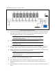
NOTE:Connectors
Make sure the shape of connectors before connection. The server port
connector and LCD connector of the server switch unit have the same
shape. You can distinguish them with its color and icon. The server port
connector is black and marked with . The LCD connector is blue and
marked with numerics of 1 to 8. Pay attention not to connect the LCD
connector to the server port.
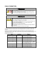
INPORTANT:Notes on connecting cables
■ Be sure to power off the server switch unit, servers, and peripheral
devices before connection. Connecting cables with these devices
being powered may cause a malfunction or a failure.
■ Plug in the keyboard and mouse with "Δ" on the connector upward.
■ Firmly secure the LCD connector (Mini D-Sub 15-pin) with screws to
the server switch unit and the server. Loose cable connection may
cause the screen display to be shifted or not to appear.
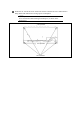
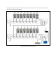
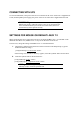
You can add N8191-10F server switch unit by using the dedicated connection cable (K410-119 (1A))
to each server port of the server switch unit or N8143-69 console unit. Such the connection is called
cascade connection.
With eight N8191-10F server switches in cascade connection, you can select a console from up to 64
servers. In cascade connection, the installation area can be greatly reduced since it requires only one
console.
The N8191-10F server switch unit in which the console is connected is called the "master", and the
N8191-10F server switch units connected to each port of the master unit are called "slaves".