N8405-024F Blade Enclosure (SIGMABLADE-H) User's Guide 855-900677-A PN# 456-01750-000 2008 Apr. 2nd Edition Note Read this guide carefully before using this product. Always keep this guide at hand so that you can see it when necessary.
FCC COMPLIANCE This product has been tested and found to comply with the limits for a Class A digital device, pursuant to Part 15 of the FCC rules. These limits are designed to provide reasonable protection against harmful interface when the device is operated in a commercial environment. This device generates, uses and can radiate radio frequency energy and if not installed and used in accordance with the instruction manual, may cause harmful interference to radio communications.
Note Keep this User's Guide handy for quick reference when necessary. Make sure to read "Notes for safe handling." When you relocate the product, make sure to take this guide with the product. Notes for safe handling This section provides information for using the product safely. SAFETY INIDICATIONS To use this product safely, follow the instructions in this User's Guide.
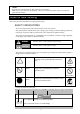
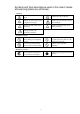
Symbols and their descriptions used in this User's Guide and warning labels are as follows: Attention Indicates the risk of electric shock. Indicates the risk of explosion. Indicates the risk of injury due to a caught hand or finger. Indicates the risk of smoke emission or fire outbreak. Indicates the risk of burn due to hot surface. Indicates the risk of injury due to rotation of objects. Indicates a general notice or warning that cannot be specifically identified.
Precautions for safety Observe the precautions for safety described in this section. The blade enclosure (SIGMABLADE-H) on which this card is installed has power units. Carefully use them to avoid any electric shock. . General precautions WARNING Do not use this product for services where critical high availability may directly affect human lives.
CAUTION Prevent water or foreign objects from the product. Do not allow water or foreign objects (e.g., pins or paper clips) to enter into the product. There is a risk of fire, electric shock, and breakdown. When such things accidentally enter the server, immediately turn off the power and unplug the cords. Contact your sales representative instead of trying to disassemble it yourself. Connect firmly. Connect interface cables, option boards, and modules to the CPU blade securely.
Power Supply and Power Cord WARNING Do not hold the power plug with wet hands. Do not disconnect/connect the plug while your hands are wet, otherwise it may cause an electric shock. Do not connect the protective earthing conductor to a gas pipe. Never connect the protective earthing conductor to a gas pipe; otherwise it may cause a gas explosion. CAUTION Plug into a proper power source. Use a proper wall outlet. Use of an improper power source may cause a fire or a leak.
Installation and handling of the rack WARNING Install the server rack ONLY in a specified or designated environment Do not install the rack on which the blade enclosure is installed in an unsuitable place. Other devices installed on the blade enclosure or the rack may be affected, a fire may occur, or the rack may fall, causing injury. For details about installation environment and quake-resistant engineering, see the manual attached to the rack or contact your maintenance service agent.
CAUTION Do not carry or install alone. Carry or install a rack with two or more people. If the rack is carried by one person, the rack may fall and cause injury or damage to physical assets. A tall rack such as a 44 U rack, in particular, is unstable if it is not fixed by stabilizers. Make sure to support the rack with two or more people to carry and/or fix it. Do not install the rack in such a manner that weight is imposed on a single spot.
Installation, relocation and storage of the blade enclosure WARNING Separate the blade enclosure into two components and carry each component with two or more people. When you want to carry the blade enclosure, separate the rear cage from the module to make the blade enclosure into two components. With no modules such as a CPU blade or power unit installed, the enclosure and the rear cage weigh 35.5kg and 31.5kg respectively. Carrying the enclosure or rear cage alone may result in injury.
WARNING Do not impose loads on the blade enclosure while it is pulled out of the rack. Do not impose loads on the top of the blade enclosure while it is pulled out from the rack. The frame may be damaged, and you may not be able to install the blade enclosure on the rack. There is a risk of the blade enclosure falling and causing injury as well. Do not cover ventilation openings. Do not cover ventilation openings of the blade enclosure. Additionally, do not cover rack openings.
Failure action WARNING Failure action. When the device fails, shut off the branch circuit breaker of the power distribution board, unplug the device, and contact your sales maintenance personnel. Disposal CAUTION Lithium battery. The EM card installed on the blade enclosure uses a lithium battery (the battery is not replaceable). Contact your NEC sales representative before disposing the EM card. Disposal and recycling.
Maintenance, cleaning and handling of internal devices WARNING Do not place your hands inside the blade enclosure. Do not place your hands inside the blade enclosure when you install or remove it. There is a risk of electric shock. Do not remove the cover attached to the blade enclosure except when necessary, such as when installing a device. Installation/removal of a device should be done one by one. CAUTION Unplug power cords before maintenance.
Disposing of your used NEC product In the European Union EU-wide legislation as implemented in each Member State requires that used electrical and electronic products carrying the mark (left) must be disposed of separately from normal household waste. When disposing of used NEC products, you should comply with applicable legislation or such terms which may have been agreed between NEC and your company regarding used products.
Handling precautions to use the device correctly Observe the following precautions to use the blade enclosure device correctly. Failure to observe the precautions can result in malfunction or mechanical error. About maintenance services Hint Diagnostic and maintenance services by personnel with expertise on maintenance of the blade enclosure are available. ● Blade enclosure - Use a rack that allows installation of the blade enclosure. - This product must be installed in a restricted access location.
Contents Notes for safety handling ........................................... 3 Installing a switch module or SAFETY INIDICATIONS .................................. 3 pass-through card .............................. 38 Symbols and their descriptions used in Removing a switch module or this User's Guide and warning labels ar pass-through card .............................. 40 as follows: ........................................................ 4 Installing a CPU blade ..............................
Removing a power unit ..................... 85 an user (EM card)........................... 108 Power unit cover ........................................... 86 Power unit settings (EM card)........ 109 Opening the power unit cover .......... 86 Verifying, backing up, and Closing the power unit cover ........... 87 restoring the EM card Moving the key box .......................... 87 configuration ..................................... 110 Power on and off ..........................................
CLI additional user .......................... 137 62 Commands ............................................................... 138 PING ................................................. 162 Commands ................................................... 138 Initializing the configuration data Command specification ........................................... 147 (restoring default values) ............... 163 Description....................................................
Configuring the IP address of the sec Configuring a time zone ................. 187 ondary NTP server .......................... 173 Displaying all information about Configuring the name of an configuration of the blade SNMP community allowing the enclosure. ......................................... 187 Get operation ................................... 173 Displaying the configuration of the CLI Configuring the name of an auto termination function ...............
(E-Keying information) ..................... 207 Configuring the language type for EM Displaying CPU blade status .......... 207 cards ............................................... 223 Configuring the power-on delay NEC Diana Scope control commands ....... 225 time of the CPU blade ................... 208 Configuring an NEC DianaScope user Displaying the power-on delay password ........................................ 225 time of the CPU blade ................... 209 Command name ..............
Preface Thank you for purchasing the N8405-024F Blade Enclosure (SIGMABLADE-H). The blade enclosure houses modules such as CPU blades, switch modules, pass-through cards, EM cards, power units, and fan units to integrate their functions and to allow CPU blades to function as servers. Read this guide before you start using the blade enclosure. Also, refer to the "User's Guide" and "Startup Guide" that come with the SIGMABLADE series.
Components The following illustrationdepicts the blade enclosure components. The illustration depicts optional modules attached to the blade enclosure that are not included as standard. Front view (When the front bezel and the power unit cover are opened) 1 10 2 3 5 6 4 1. Blade slot 10. Separator From the upper left: Slot 1 – Slot 8 From the lower left: Slot 9 – Slot 16 7 8 9 A plate to separate the blade slot into the upper and lower tier (when installing a full-height blade, remove this plate) 2.
Rear view 23 2 1 3 4 5 Close-up of the EM card 7 17 11 8 8 ID M MNG LAN RST Active 9 6 10 18 12 11 12 13 14 ⑬ ⑥ 15 16 17 18 19 20 21 13 14 15 16 22 1. Fan unit 11. Dedicated Management LAN connector (EM card) From the upper left: Fan unit 1 – Fan unit 5 From the lower left: Fan unit 6 – Fan unit 10 Connected to a network system that supports 10BASE-T/100BASE-TX (auto-negotiation only) 2. Fan LED (green/amber) 12.
Installation Checking components See the attached list to check that you have all the accessories and components. Installing the blade enclosure on a rack Install the blade enclosure on a rack. This section also describes how to remove the blade enclosure as well. WARNING Make sure to follow the instructions and notes to use the blade enclosure and other devices safely. There is a risk of death or serious injury. For more information, see the descriptions on page 3.
Required Tools A torx driver (T25) is necessary to install the blade enclosure on a rack. Installation Procedure Complete the following steps to install the blade enclosure on a rack. See the instructions that come with the rack as well. Check Before you install the blade enclosure on a rack, remove the doors at the front and rear of the rack. For information on removing the rack doors, see the instructions that come with the rack. ● Check where the blade enclosure will be installed.
● Attach core nuts/clip nuts. Attach core nuts or clip nuts inlcuded with the blade enclosure at the positions determined in "Check where the blade enclosure is installed." Attach a total of four core nuts or clip nuts on the rack front (two each on the right and left side). Check Check that the core nuts/clip nuts are attached on the same height on the right and left side of the rack. ● Attach rail brackets. Attach rail brackets to the rack.
2. Use a torx driver (T25) to remove the screws at the rear of the blade enclosure (two each on the right and left side for a total of four), and then bend the hinges outward so that the rear cage will not hit them when it is removed. Stop lever One each on the right and left side 3. Firmly hold the handles of the blade enclosure, which are located at its rear, on the right and left side and slowly slide the enclosure out approximately 10 cm. This step should be done by two or more people. 4.
● Install the blade enclosure on the rack. Hold the blade enclosure with its front facing front with 2 or more people. Slowly put the L-shaped frames on both the right and left side of the blade enclosure on the L-shaped frames of the rail brackets that have been attached to the rack. Important ● When you carry the enclosure, hold the four handles at both sides of the enclosure (two each on the right and left side).
Removing the blade enclosure from the rack Follow the steps below to remove the blade enclosure from the rack. CAUTION Make sure to follow the instructions and notes to use the blade enclosure and other devices safely. There are risks of a burn, injury, or damage to physical assets. For more information, see the descriptions on page 3 ● Separate the blade enclosure into two components and carry them with two or more people. ● Be careful not to hurt your fingers.
● Hold the four handles at both sides of the enclosure (two each on the right and left) for carrying. 9. Firmly hold the blade enclosure and remove it from the rack. To remove any parts attached to the rack, see the description in "Installing the blade enclosure." To install the rear cage on the enclosure, see "Installing the blade enclosure.
Installing a switch module or pass-through card The following illustration shows slots where switch modules and pass-through cards can be installed: Slot Slot Slot Slot 1 3 5 7 Slot 2 Slot 4 Slot 6 Slot 8 Install switch modules and pass-through cards according to the specifications described on the following pages. Slots without switch modules or pass-through cards should have slot covers installed.
Installable switch modules and pass-through cards A maximum of eight switch modules and pass-through cards can be installed on this blade enclosure (a maximum of six 4G FC switch modules (12 ports/24 ports) and FC pass-through cards can be installed). The number and combination of switch module slots that can be used depends on the types and combination of switch modules, pass-through cards, and mezzanine cards.
Internal connection between CPU blades and switch modules If there is no description for the products that support your CPU blades, contact your NEC sales representative to obtain the latest User's Guide.
CPU blade (NEC Express5800/120Bb-m6) Expansion slot 2 (For both type 1 and 2) (4) (3) (2) (1) Expansion slot 4 (For both type 1 and 2) (4) (2) (1) (2) (1) Switch module slot 8 Switch module slot 7 (2) (3) (1) (2) (2) (1) (1) Switch module slot 6 Switch module slot 5 (2) Expansion slot 1 (Dedicated to type 1) (2) (1) Standard interface (Dedicated to LAN) (1) (2) (3) (4) (1) Switch module slot 4 (2) Expansion slot 3 (Dedicated to type 1) (2) (1) Switch module slot 3 (1) (2) Swi
CPU blade (NEC Express5800/140Ba-10) Expansion slot 4 (For both type 1 and 2) (4) (3) (2) (1) Expansion slot 2 (For both type 1 and 2) (4) (9) (1) (9) (1) Switch module slot 8 Switch module slot 7 (9) (3) (1) (2) (9) (1) (1) Switch module slot 6 Switch module slot 5 (9) Expansion slot 3 (Dedicated to type 1) (2) (1) Standard interface (Dedicated to LAN) (1) (2) (3) (4) (1) Switch module slot 4 (9) Expansion slot 1 (Dedicated to type 1) (2) (1) Switch module slot 3 (1) (9) Swi
The following table lists mezzanine cards and their supported modules. Find your mezzanine card on the table and check its supported module to see appropriate combinations. Before you install a mezzanine card, check its type and number of ports to mount it on an appropriate slot.
Alignment of switch module slots Blade enclosure (SIGMABLADE-H) Switch module slot 1 Switch module slot 2 Switch module slot 3 Switch module slot 4 Switch module slot 5 Switch module slot 6 Switch module slot 7 Switch module slot 8 Single-wide Double-wide ・ ・ ・ ・ Since a standard LAN of CPU blades is connected to slots 1 and 2, select and install 1Gb intelligent L2 switch, 1Gb intelligent L3 switch, or 1Gb pass-through card.
Installing a switch module or pass-through card Follow the steps below to install a switch module or pass-through card. A switch module or pass-through card can be installed or removed even if the blade enclosure is powered on (switch modules/pass-through cards in other slots are working). This section provides an example of installation. Follow the same steps for installation on other slots.
3. Place the switch module/pass-through card carefully on a clean, flat table and open (release) the ejector. When you open the ejector, press the stopper locking the ejector rightward. The illustration depicts a device with a stopper. If there is no stopper, the action indicated by (1) is not necessary. (2) (1) 4.
Removing a switch module or pass-through card Follow the steps below to remove a switch module/pass-through card. Depending on the switch module/pass-through card type, a different procedure may be required. In this case, follow the instructions in the User's Guide of the switch module/pass-through card instead. 1. If any interface cables are connected to the switch module/pass-through card, remove them. 2. Open the ejector. When you open the ejector, press the stopper locking the ejector rightward.
Installing a CPU blade The following illustration shows slots where CPU blades can be installed: Slot 1 Slot 9 Slot 2 Slot 4 Slot 6 Slot 8 Slot 7 Slot 3 Slot 5 Slot 10 Slot 12 Slot 14 Slot 16 Slot 15 Slot 11 Slot 13 Install CPU blades sequentially in the slots (1 to 16) in the following illustration. Install slot covers on slots with no CPU blades.
Important ● The CPU blade blank cover that can be installed on the blade enclosure is N8405-030. ● To install a full-height blade, remove the separator dividing the target blade slots. For safety reasons, removal of the separator should be done only by sales maintenance personnel. Contact your sales maintenance personnel to remove the separator. ●To install a half-height blade, a separator should be installed on the target blade slots. The blade enclosure is shipped with separators installed.
Notes for installation of a half-height double-wide blade: Slot 1 Slot 2 Slot 4 Slot 6 Slot 8 Slot 7 Slot 3 Slot 5 A half-height double-wide blade can be installed. A half-height double-wide blade cannot be installed on slots starting with an even slot number.
Notes for installation of a full-height and single-wide blade: Slot 1 Slot 2 Slot 4 Slot 6 Slot 8 Slot 7 Slot 3 Slot 5 Blade slot "block" Blocks are separated by a non-removable frameand are full-height and double wide. A half-height blade and a full-height blade cannot occupy the same block.
Installable CPU blades A maximum of 16 CPU blades shown below can be installed in this blade enclosure. CPU blades of different types can be installed in one blade enclosure. If there is no description for your product, contact your NEC sales representative to obtain the latest User's Guide.
Installing a CPU blade Follow the steps below to install a CPU blade. A CPU blade can be installed or removed even if the blade enclosure is powered on (CPU blades in other slots are working). An example of installation is provided. Follow the same steps for installation on other slots. Depending on the CPU blade type, a different procedure may be required. In this case, follow the instructions in the User's Guide of the CPU blade instead.
3. If the CPU blade has any covers on the connectors on the side that is inserted into the blade enclosure, remove them. 4. Open the CPU blade ejector. If the ejector is secured by a screw, loosen it. 5. Hold the CPU blade with its midplane connector facing the blade enclosure and the ejector facing down. 6. Put the end of CPU blade board on the guide rails located at the upper and lower sides of the blade enclosure and slowly push the CPU blade into the blade enclosure.
Removing a CPU blade Follow the steps below to remove a CPU blade. Depending on the CPU blade type, a different procedure may be required. In this case, follow the instructions in the User’s Guide of the CPU blade instead. 1. Shut down the OS of the CPU blade and turn the power off. For information on how to shut down the OS of a CPU blade and how to turn the power off, see “Powering on and off a CPU blade” and the User’s Guide of the CPU blade. 2. Loosen the screws securing the CPU blade. 3.
Assembling a full-height CPU blade slot cover When a full-height CPU blade is installed on a blade slot block, one full-height CPU blade slot cover should be installed on the blank slot in the same block. By combining two half-height CPU blade slot covers, a full-height CPU blade slot cover can be assembled. See the following instructions to assemble a full-height CPU blade slot cover. Important Keep all screws.
Move on to the CPU blade slot cover for the lower level. 3. Remove the top 2 screws from the right side. Right side 4. Loosen the lower 2 screws on the right side and the 2 screws on the left side. Right side Left side 5. Extend the CPU blade slot cover until the 2 screws on the right side line up with the center of the elongated hole. Tighten the 4 screws to secure the blade slot cover. To the center of the elongated hole The CPU blade slot cover for the lower level is now ready to be combined.
6. Use the screws removed in Step 1 to connect Part B of the CPU blade slot cover for the upper blade (described in Step 2) to the CPU blade slot cover for the lower level. Part B of the CPU blade slot cover for the upper level CPU blade slot cover for the lower level 7. Connect Part A of the CPU blade slot cover for the upper level to the blade slot cover assembled in Step 6.
8. Use the 4 screws removed in Step 1 and 3 to fasten 4 places in the right and left (2 each in the right and left) to secure the blade slot covers. The screws should be tightened at the bottom of the elongated holes (the position where a CPU blade slot cover is extended most) as shown in the figure.
Disassembling a full-height CPU blade slot cover To disassemble a full-height CPU blade slot cover into the original two CPU blade slot covers, see the "Assembling a full-height CPU blade slot cover" and reverse the steps. Important Keep all screws. To avoid screws and parts falling into the cabinet, device, or module, do not disassemble a full-height CPU blade slot cover near any cabinet, device, or module.
Installing the EM card The EM card that can be installed on the blade enclosure is N8405-027. Important The following illustration shows where EM cards can be installed: Slot 1 Slot 2 The EM card that is included as standard should be installed on (1) in the illustration below. If you add another EM card, it should be installed on (2). Attach a slot cover to a slot where no EM card is installed.
Installing an EM card Follow the steps below to install an EM card. An EM card can be installed or removed even if the blade enclosure is powered on. An example of installation is provided. Follow the same steps for installation on another slot. WARNING Make sure to follow the instructions and notes to use the blade enclosure and other devices safely. There is a risk of death or serious injury. For more information, see the descriptions on page 3. ● Do not place your hands inside the blade enclosure.
Removing an EM card Follow the steps below to remove an EM card. 1. If any cables are connected to the EM card, remove them. 2. Open the release lever. When you open the release lever, press the stopper securing the release lever rightward. (2) (1) Fully open the release lever until it stops. Check 3. Hold the release lever and pull the EM card out of the blade enclosure until you can hold its frame with both of your hands (approximately 10cm).
Installing a fan unit Additional fan units are options that can be installed when more fans are needed according to the number of CPU blades or other modules installed on the blade enclosure. See "Components" described earlier. Important The fan unit that can be installed on the blade enclosure is N8405-026. The fan unit N8405-026 is a set of two fan units. The number of fan units required depends on the number of modules, such as CPU blades.
Slots on which fan units are installed depend on the total number of fan units installed on the blade enclosure. Install fan units on the slots with the "○" mark in the following illustrations according to the number of fan units you are installing. Attach slot covers to slots with no fan units. The total number of fan units that should be installed is determined by the number and types of modules that are installed.
When eight fan units are installed (four units as factory def ault plus four additional units) Slot 1 Slot 2 Slot 3 Slot 4 Slot 5 Slot 6 Slot 7 59 Slot 8 Slot 9 Slot 10
Fan unit installation guide In principle, blades are installed on slots starting from the far-left slot, although there are exceptions depending on the number and types of blades. See the User's Guides of the blades.
Installing a fan unit A fan unit can be installed/removed even if the blade enclosure is powered on. The following section is an example of installing a fan unit. Use the same method to install fan units to other slots. WARNING Make sure to follow the instructions and notes to use the blade enclosure and other devices safely. There is a risk of death or serious injury. For more information, see the descriptions on page 3. ● Do not place your hands inside the blade enclosure.
2. To install a fan unit on the upper level of the blade enclosure, hold the fan unit handle and the bottom of the unit firmly with the handle facing down and insert the fan unit slowly into the blade enclosure halfway (approximately 10 cm). To install a fan unit on the lower level of the blade enclosure, hold the fan unit handle and the bottom of the unit firmly with the handle facing up and insert the fan unit slowly into the blade enclosure halfway (approximately 10 cm).
Installing the front bezel The front bezel is a recommended option to protect the CPU blades installed on the blade enclosure. Installation and removal of the front bezel and its filter should be done only by sales maintenance personnel. Contact your sales maintenance personnel to install or remove the front bezel and its filter. Important ● The front bezel that can be installed on the blade enclosure is N8405-028.
Opening the front bezel The front bezel can be opened even if the blade enclosure is powered on. To remove a CPU blade installed on the blade enclosure, keep the front bezel open (the front bezel is a recommended option). For information on how to remove a CPU blade, see "Installing a CPU blade" on page 41. CAUTION Make sure to follow the instructions and notes to use the blade enclosure and other devices safely. There are risks of a burn, injury, or damage to physical assets.
Closing the front bezel Follow the steps below to close the front bezel. The front bezel can be closed even if the blade enclosure is powered on. Close the front bezel after installing CPU blades. For information on installing a CPU blade, see "Installing a CPU blade" on page 41. The following description assumes the front bezel is already attached to the blade enclosure. 1. Close the front bezel. Key slot 2.
Connecting cables Connect cables according to the requirements of your environment. For information on connecting cables, see the manuals of the installed devices. Front Use a K410-150(00) SUV cable, which is sold separately, to connect the SUV connector located on the front side of a CPU blade to the local console. * The SUV connector and the local console are not supported by some CPU blades. For details, see the User's Guide of the CPU blade.
Monitor connector SUV cable USB connector FDD USB connector (Not connected) Serial connector Blade enclosure These input and output devices are collectively called "local console." CPU blades on the blade enclosure can be directly operated when they are connected to a keyboard, video monitor, and mouse via the SUV cable attached to the blade enclosure.
Rear Connect network cables (RJ-45), interface cables to be connected to switch modules, and power cords to the rear of the blade enclosure. EM serial console When the serial (COM) port of an EM card is connected to a PC by a serial cable (D-Sub 9-pin connector, crossover cable), you can operate the CPU blades and check their status. PC CLI Blade enclosure These input and output devices are called "EM serial console.
EM console When the LAN connector (management LAN connector) of an EM card is connected to a PC by a network cable (RJ-45), you can remotely control the CPU blades. You can virtually allocate modules, such as DVD, CD, and floppy disk drives on the PC to the CPU blades (i.e., remote media), and operate and check the status of the CPU blades.
LAN console When the LAN connector of a switch module or pass-through card is connected to a PC by a network cable (RJ-45), you can remotely control and operate CPU blades. PC Network Mg ESMPRO Mg DianaScopeMg (Network hub) Blade enclosure These input and output devices are collectively called "LAN console" and the network is called "user LAN." You can operate CPU blades and switch modules on the blade enclosure on a PC via a LAN network.
SFP connector (switch module) See the User's Guides of the 4G FC switch (12 ports) (N8406-019), 4G FC switch (24 ports) (N8406-020), and GbE intelligent switch (L3)(N8406-023). SFP connector (pass-through card) See the User's Guide of the 4G FC pass-through card (N8406-017).
Power connector Connect the power cords to the AC inlets of the power units installed on the power unit slots 1 and 4 at the rear of the blade enclosure (these units are standard equipment). If any optional power units are installed on the power unit slots 2, 3, 5, and 6, connect the power cords to the AC inlets of the optional power units as well.
Rear view The illustration depicts fouraddition al power supply units installed. Blade enclosure Rack frame Rack frame Fix to the rack frame. Fix to the rack frame. Fix to a blade enclosure. Fix a power cord to a power supply retention tie by a cable tie Power supply Cable tie Draw the cable tie tip through the cable tie hole and then through a retention tie hole by referring to this illustration. * When cable clamps are provided as standard, use them instead.
Installing cable clamps Follow the steps below to install cable clamps. 1. Remove cable ties. When cable ties are not fixed, skip this step. When power cords are fixed to po wer supply retention ties, remove t he cable ties. Power supply retention tie Cable tie Power cord 2. Remove the power supply retention ties. When the blade enclosure has no power supply retenti on ties, skip this step. When the blade enclosure has power supply retention ties, remove them with pliers.
3. See the following illustrations to check where the cable clamp should be installed. Check The shapes of cable clamps (L) and (R) are not the same. See the following illustrations to check the locations of the tabs on the cable clamps and the direction in which they should be installed.
4. Attach a cable clamp (L) to the blade encl osure. Clip Place the cable clamp (L) under the power cord and adjust the power cable to the clip of the cable clamp. Open the clip of the cable clamp and inser t the power cord into the clip. Do this for each power cord (up to three cords). ② Bring the cable clamp to the blade enclosu re and carefully insert the tabs of the cabl e clamp into the slots on the blade enclos ure.
Removing a power cord form a cable clamp Follow the steps below to remove a power cord from a cable clamp. Firmly hold the clip of the cable clamp with pliers and twist it to release the clip. Remove the power cord.
Important ● Note that a maximum of 2250W/2273VA power is supplied from each power unit. ● Fix power cords firmly to the blade enclosure. If power cords are not fixed, they may be removed while the devices are running, which can result in data loss or malfunction of the device. ● Contact NEC's sales representative if you use an uninterruptible power supply system.
Emergency power off (EPO) In of the event of an environmental disaster or problem (e.g., fire, earthquake, etc.), the emergency power off (EPO) procedure can be performed to shut down computers, uninterruptible power supply systems (UPS), and air conditioners to prevent further damage. Because there is a risk of data corruption when EPO is performed, clearly define scenarios to perform EPO in advance. Operate your system with an understanding of these scenarios and the procedure to perform EPO.
Emergency power off switch For the safety of the entire computer room, install an emergency power off switch that allows shutdown of power supplied to all devices in the computer room in case of emergency. This emergency power off switch should be installed near the main doorway so that an operator can use it when he/she evacuates the room. The emergency switch should not require technical skill or expertise to use.
Power unit Additional power units are options that are installed when CPU blades and other modules on the blade enclosure require more power units or when you want to enable power redundancy functions. WARNING Make sure to follow the instructions and notes to use the blade enclosure and other devices safely. There is a risk of death or serious injury. For more information, see the descriptions on page 3. ● Air exhausted from power fans may get hot.
The power units that are equipped as standard should be installed on (1) (there are two slots shown as (1)). When additional power units are installed, install them in the order of (2) to (5) as shown in the illustration below. Slots with no additional power unit installed should have slot covers attached. For information on the number of power units required, see "Power unit installation guide.
Power unit installation guide The number of power units required is determined by the total power consumption of blades. See the following to determine the number of power units required for your system. *If you need more detailed information, please contact your sales agent. 1.
Installing a power unit Follow the steps below to install a power unit. A power unit can be installed or removed even if the blade enclosure is powered on. Power units can be removed only in a redundancy configuration. If you want to remove a power unit in a non-redundancy configuration, power off all devices on the blade enclosure. Installation can be done in both redundancy and non-redundancy configurations. An example of installation is provided below.
5. Hold the power unit frame with the power unit stopper facing up. Push the frame at the front of the power unit and slowly insert the power unit into the blade enclosure. Important Do not touch the plug terminals of the power unit. Do not insert a wire or metal object. Do not let dust or waste enter the power unit. 6. Close the power unit ejector. Removing a power unit Follow the steps below to remove a power unit: 1. Check which power unit you wish to remove. 2.
Power unit cover Opening the power unit cover The power unit cover can be opened even if the blade enclosure is powered on. When you install or remove a power unit, keep the power unit cover open. If you keep using the system, close the power unit cover. For information on how to remove a CPU blade and a power unit, see "Installing a CPU blade" on page 41 and "Power unit" on page 81, respectively. CAUTION Make sure to follow the instructions and notes to use the blade enclosure and other devices safely.
Closing the power unit cover The power unit cover can be closed even if the blade enclosure is powered on. After installing the power units, close the power unit cover. For information on how to install a CPU blade and a power unit, see "Installing a CPU blade" on page 41 and "Power unit" on page 81, respectively. 1. If the key box is not located at the key slot of the power unit cover, slide the key box to place it in an appropriate position.
Power on and off Powering on and off the blade enclosure WARNING Make sure to follow the instructions and notes to use the blade enclosure and other devices safely. There is a risk of death or serious injury. For more information, see the descriptions on page 3. ● Do not place your hands inside the blade enclosure. Important Make sure to follow the instructions to power on and off devices. If you do not follow the instructions, data may be corrupted or the devices may malfunction.
Powering on and off the blade enclosure with uninterruptible power supply system (UPS). Follow the steps below to power on the blade enclosure using an uninterruptible power supply system (UPS). When you use a UPS, contact your NEC sales representative. Depending on the types of modules and units and how they are used on the blade enclosure, a different procedure may be required. In this case, follow the instructions in the User's Guides of the modules and units instead. 1.
Powering on and off a CPU blade There are four ways to power on and off the CPU blades installed on the blade enclosure. Power on the video monitor and other connected devices and then power on the CPU blades in one of the following ways. For information on the CPU blades, including their behavior after power-on and checking the behavior, see the User's Guides and manuals of the CPU blades.
Powering on and off a CPU blade by its power switch A CPU blade on the blade enclosure can be powered on and off by using the power switch located on the front of the CPU blade. For details, see the User's Guide and manuals of the CPU blade. When a CPU blade is powered on by its power switch, the DC power supply from power units on the blade enclosure starts. Then the power LED of the CPU blade turns green, showing the CPU is now powered on.
Powering on a CPU blade by the network serial (COM) port of an EM card A CPU blade on the blade enclosure can be powered on and off by a network connected to the management LAN connector of the EM card or the serial port (COM) of the EM card. For details, see the User's Guide of the CPU blade. This section describes how to power on and off a CPU blade by a CLI from the EM serial console or the EM console. For information on other ways to power on and off, see the User's Guide of the CPU blade.
3. From the CLI, run the following command for restarting a specified CPU blade. For details, see "Commands.
Memo 94
Memo 95
Command-line interface (CLI) (EM card) A command-line interface (CLI) allows configuring and managing the modules installed on the blade enclosure, including CPU blades and switch modules. A CLI can be used on the EM serial console and the EM console. Connecting a cable to a console For information on how to connect a cable, refer to "EM serial console (serial connection)" and "EM console (Telnet connection)." Starting a console There are three ways to use a CLI.
EM console (Telnet connection) You can use a CLI via a telnet connection from the EM console. Install terminal emulator software supporting telnet. For settings of the terminal emulator software, refer to the manual of the software. To check if the telnet function is enabled, execute the SHOW NETWORK command (the telnet function is enabled by default). If the function is disabled, execute the ENABLE TELNET command to enable the telnet function. For details on each command, refer to "Commands.
Initial settings Configure the initial settings of modules installed on the blade enclosure, such as EM cards and CPU blades, by using the EM serial console or EM console. For connections and settings of the EM serial console and the EM console, refer to "Connecting cables." Check The default password for "Administrator" is printed on the label of an EM card or the release lever. Each EM card has a different default password for "Administrator.
command. User settings (EM card) 1. Confirm that the EM card is powered on. 2. Confirm that you have logged in as "Administrator" or a user whose access right is ADMINISTRATOR or OPERATOR from a CLI of the EM serial console or EM console. If you have not, log in as "Administrator" or a user whose access right is ADMINISTRATOR or OPERATOR. 3. Configure the following information by running commands on the CLI. For details, refer to "Commands.
Rack settings (EM card) 1. Confirm that the EM card is powered on. 2. Confirm that you have logged in as Administrator or a user whose access right is ADMINISTRATOR or OPERATOR from a CLI of the EM serial console or EM console. If you have not, log in as "Administrator" or a user whose access right is ADMINISTRATOR or OPERATOR. 3. Configure the following information about the rack by running commands from the CLI. For details, refer to "Commands.
― Blade enclosure name (required for report processing) Configure the name of the blade enclosure on which the EM card is installed (up to 32 characters). Specify any unique name to identify the blade enclosure. SET ENCLOSURE NAME ― Blade enclosure asset number (optional) Configure an asset number of the blade enclosure on which the EM card is installed (up to 32 characters).
Network settings (EM card) 1. Confirm that the EM card is powered on. 2. Confirm that you have logged in to the EM card as Administrator or a user whose access right is ADMINISTRATOR or OPERATOR from the CLI of the EM serial console or EM console. If you have not, log in as "Administrator" or a user whose access right is ADMINISTRATOR or OPERATOR. 3. Determine the network configuration. Important - Confirm in advance that IP addresses to be configured are available in your network.
― Configuration example The following is an example. Configure each IP address and subnet mask according to your usage environment. (1) EM card -network configuration Floating IP 192.168.1.4 (active EM) Floating IP 192.168.1.5 (stand-by EM) Static IP address 192.168.1.6 (EM card slot 1) Static IP address 192.168.1.7 (EM card slot 2) Four consecutive IP addresses Specify the IP address of floating IP (active EM) (2) CPU blade (Slot 1~16) -network configuration 192.168.1.8 Slot1 Slot2 192.168.1.9 Slot3 192.
When you are using DianaScope, the last numeric value of the IP address of a floating IP (active EM) must be multiples of 4 (e.g., 192.168.1.4 and 192.168.1.8). Important Hint By specifying a floating IP (active EM) by the SET NETWORK ADDRESSRANGE command, consecutive numbers are automatically allocated to IP addresses of the floating IP (standby-EM), static IP address (EM card slot 1), and static IP address (EM card slot 2). Reserve four consecutive IP addresses in advance.
(it takes about 5 seconds to complete the command). SET NETWORK GATEWAY (Example) SET NETWORK GATEWAY 192.168.1.99 ― DNS configuration (required to register one or more DNS server when the DNS function is used) Register a DNS server. By default, the DNS server configured first is "primary." It is possible to delete a registered DNS server by the REMOVE NETWORK DNS command.
or OPERATOR. 3. Run the following commands from a CLI to configure settings. For details, refer to "Commands." ― Configuring community name To use the SNMP function, the write community setting is required. Read and trap community settings are optional. Configure community names (the default community name value for read, write, and trap operations is "public").
For details, refer to "Commands." After making changes, execute the SHOW SNMP command. For performing the SNMP test, execute the TRAPTEST command. When you are using NEC ESMPRO Manager, the message, "AlertManager tested: Notification test is performed. (TEST-AlertManager)" is displayed. Setting module access right for an user (EM card) 1. Confirm that the EM card is powered on. 2.
Power unit settings (EM card) 1. Confirm that the EM card is powered on. 2. Confirm that you have logged in to the EM card as Administrator or a user whose access right is ADMINISTRATOR or OPERATOR from the CLI of the EM serial console or EM console. If you have not, log in as "Administrator" or a user whose access right is ADMINISTRATOR or OPERATOR. 3. Run the following commands from a CLI to configure the power unit settings. For details, refer to "Commands.
Verifying, backing up, and restoring the EM card configuration Check Verification, backup, and restoration of the configuration information must be operated by "Administrator" or a user whose access right is ADMINISTRATOR. Verification, back up, and restoration of the configuration information must be performed on the active EM card. For details about active EM card, refer to "EM card" on page 123.
Follow the steps below to restore configuration information. To restore configuration information, you need the backup of the configuration information. Check By restoring configuration information, values in each setting are overwritten. For setting information to be backed up/restored, see "SET FACTORY" in "Commands." Before restoring configuration information, confirm that the settings information of each module, including network settings, can be overwritten. 1.
DianaScope settings (EM card) When using DianaScope Manager, you should create a user password of DianaScope Gateway on an EM card. Follow the steps below to create a user account. DianaScope Manager requires an authentication key when you register a server. Configure the user password as the authentication key. Configure the static IP address of an EM card as the IP address of a server to be registered. For the static IP address of an EM card, refer to "Network settings (EM card).
2. Confirm that you have logged in to the EM card on the CLI of the EM serial console or EM console. 3. Run the following command on the CLI to connect to a switch module and configure settings. For details on the procedure after connection is achieved, refer to "Commands" and the User's Guide of the switch module. ― Connecting a console to a switch module CONNECT SWITCH Hint Generally, a pass-through card does not need to connect to consoles.
Checking operational status You can check how the blade enclosure and modules on the blade enclosure are operating. The operation status can be confirmed on the CLI of the EM serial console or EM console. Blade enclosure 1. Confirm that the EM card is powered on. 2. Confirm that you have logged in to the EM card on the CLI of the EM serial console or EM console. 3. Run the following command on the CLI. For details, refer to "Commands.
Power unit 1. Confirm that the EM card is on. 2. Confirm that you have logged in to the EM card on the CLI of the EM serial console or EM console. 3. Run the following command on the CLI. For details, refer to "Commands.
Updating the enclosure manager firmware This section explains how to update the firmware of an EM card (enclosure manager firmware). The EM firmware can be updated on the CLI of the EM serial console or EM console. Important ● Do not shut down the power, such as AC power or uninterruptible power supply system (UPS,) of the blade enclosure while you are updating the EM firmware. If the power is shut down during the update, it will not only result in failure to complete the update but also malfunction.
Setting EM firmware image To update the EM firmware, you have to provide a new EM firmware image file on an external server. The following transfer protocols are supported: tftp, ftp service, or http. Hint When you use a firewalled server to set an EM firmware image, make sure that the target port is available. When using an ftp server, make sure that the ftp server is set to passive mode.
Updating the EM firmware Check The EM firmware must be updated by "Administrator" or a user whose access right is ADMINISTRATOR. Update the EM firmware from the active EM card. For details on active EM card, refer to "EM card" on page 123. 1. Confirm that the EM card is powered on. 2. Confirm that you have logged in to EM card as Administrator or a user whose access right is ADMINISTRATOR from the CLI of the EM serial console or EM console.
5. Run the following command on the CLI to update the EM firmware. For details, refer to "Commands." This command takes some time to update the EM firmware. After the EM firmware has successfully been updated, the EM card is automatically restarted. ― Updating the EM firmware Updates the EM firmware of the EM card. Specify the URL (tftp/ftp/http) on which EM firmware image is set for .
Password recovery You can change the password of "Administrator" to the initial password and show the initial password on the monitor by using the EM serial console. Use this function only when you forget the password of "Administrator." Check Password recovery cannot be operated on the EM console. Use the EM serial console. Password recovery should be done on the active EM card. 1. Confirm that the EM card is powered on. 2. Confirm that the EM card is connected to the EM serial console.
Replacing modules Modules installed on the blade enclosure, such as switch modules/pass-through cards, CPU blades, EM cards, FAN units, and power units can be replaced even if the blade enclosure is powered on (i.e., when other CPU blades and switch modules/pass-through cards are operating). The conditions under which replacement can be performed may differ from one module to another. For further information, refer to the information on your module.
the power/status LED behaves differs depending on the switch module/pass-through card. Refer to the User's Guide of the switch module/pass-through card.. When you give a name to a switch module/pass-through card, the name is registered in the module itself. After a switch module/pass-through card is replaced, reconfigure the name using the SET SWITCH NAME command as necessary. For details on the commands, refer to "Commands." Hint CPU blade This section explains how to replace a CPU blade.
EM card This section explains how to replace an EM card. An EM card can be replaced even if the blade enclosure is powered on. 1. Confirm which EM card you are replacing. Important When you use the blade enclosure with only one EM card, make sure that the configuration data is backed up. Otherwise, the initial settings of the blade enclosure may be deleted. User passwords are not backed up. Reconfigure each user's password after restoring the configuration data.
When a second EM card is installed in slot 2, if a failure occurs on the active EM card, the stand-by EM card automatically turns to active. Important Many functions are restricted on the stand-by EM card. For details, see "Commands." Unless there is a reason not to use the active EM card. If you set the configuration data using a CLI on the active EM card, the configuration data is automatically set to the stand-by EM card as well.
Fan unit This section explains how to replace a fan unit. A fan unit can be replaced even if the blade enclosure is powered on. Important Quickly replace a fan unit if the blade enclosure is powered on. If you use the blade enclosure with the fan unit removed, the cooling efficiency will degrade. Make sure to install a fan unit or fan unit slot cover. 1. Confirm which fan unit you are replacing. 2. Remove the fan unit. See "Installing a fan unit." 3. Install a new fan unit in the fan slot.
Power unit This section explains how to replace a power unit. A power unit can be replaced even if the blade enclosure is powered on. 1. Confirm which power unit you are replacing. 2. If the power unit is not redundantly configured, power off all the CPU blades installed in the target slot. Important To remove a power unit in a non-redundant configuration, power off all devices on the blade enclosure. Quickly replace a power unit if the blade enclosure is powered on.
Memo 127
Memo 129
Command input Specifications How to start a CLI How to start The EM SIGMABLADE-H firmware logs in to the EM firmware via one of the following three and starts a CLI. 1: EM serial console 2: Telnet 3: SSH Via the EM serial console An EM card is equipped with a serial port to allow operation from a remote PC. When you connect a PC to an EM card using a serial cable, the system console of the EM firmware is displayed. Serial cable connection parameter Use a cross cable for a serial cable.
NEC SIGMABLADE Enclosure Manager Version 01.00 1Z34AB7890 login: Administrator Password: NEC SIGMABLADE Enclosure Manager (01.00) Type 'HELP' to display a list of valid commands. Type 'HELP ' to display detailed information about a specific command. Type 'HELP HELP' to display more detailed information about the help system.
How to enter a command Basics You can enter a command by logging in to a CLI via the EM serial console or telnet/SSH. How to enter a command Enter a command defined in this document after a prompt is displayed. When a command is correctly entered, the CLI executes a process according to the command. Only one command can be specified in a line at the same time. Multiple commands cannot be specified at the same time. Depending on a command, you can specify multiple arguments.
You need to specify the range of values for some commands. You can specify a range of values by connecting two values with "-" (hyphen). Enter a space between a value and '-' (hyphen). Example: When specifying 1 through 9 "1 - 9" You can connect multiple specifications by connecting them with ',' (comma). Enter a space between a value and ',' (comma). Example: When specifying 1 and 5. "1 , 5" URL specification URL needs to be specified for argument in some commands.
This section explains key operation for entry when a prompt is displayed. You can delete entered data by the Back Space key as you do in the ordinary key operation for entering information. The following functions are available to support key entry of information.
User account management Overview The CLI of SIGMABLADE-H EM firmware manages where a user can access. The EM firmware supports the user account management commands for managing where a user can access. Default user Default user is a user that can be used with no modification on the user management information For SIGMABLADE-H, the following user is configured by default.
Each EM card has a different password for "Administrator" by default. The initial password is displayed only on EM serial console of EM firmware when an EM firmware is started by "password recovery." For information on password recovery, refer to "Password recovery" on page 120. CLI additional user You can add or delete a user by using the CLI command. You can give an added user ADMINISTRATOR, OPERATOR or USER as access right according to the access range of the user.
Commands Commands The following table shows CLI commands supported by the SIGMABLADE-H EM firmware. Indications in the "Access rights" column A: operation by Administrator is possible. O: operation by Operator is possible. U: operation by User is possible.
Command SHOW TOPOLOGY Access rights Description A/O/U When multiple blade enclosures are installed on the same rack, displays the connection status of the blade enclosures. User management command ADD USER A Adds a system. user to Default value the ASSIGN [SERVER | SWITCH] A ASSIGN EM A DISABLE USER A Up to 30 users can be registered. The user defined by the system (Administrator) cannot be added. Assigns access permission to CPU blades and switch modules to the specified user.
Command Access rights Description Default value from the specified user. System management command CLEAR SWITCH A/O Terminates a serial SESSION console session on a switch module. PING A/O/U Sends PING (ICMP Echo command) for a specified IP address or server name. SET FACTORY A Restores settings of the EM firmware to their factory defaults. Only users with the ADMINISTRATOR rights can use this command. Enclosure network management command ADD NETWORK A/O Configures DNS servers.
Command Access rights REMOVE SNMP TRAPRECEIVER SET NETWORK ADDRESSRANGE A/O SET NETWORK DOMAIN A/O SET NETWORK GATEWAY A/O SET NETWORK NTP POLL A/O SET NETWORK NTP PRIMARY A/O SET NETWORK NTP SECONDARY SET SNMP COMMUNITY READ A/O SET SNMP COMMUNITY WRITE A/O SET SNMP COMMUNITY TRAP A/O SET SNMP CONTACT A/O SET SNMP LOCATION A/O SET SNMP LOCATION ENCLOSURE SET SNMP RACKHEIGHT A/O SET SNMP TRAPACKPORT A/O SHOW NETWORK A/O A/O A/O A/O/U Description Default value "ADD TRUSTED HO
Command SHOW SNMP Access rights A/O/U Description Default value MAC address of the EM card Web server settings (Enable/Disable) SNMP settings (Enable/Disable) SSH settings (Enable/Disable) Telnet settings (Enable/Disable) NTP settings (Enable/Disable) TRUSTED HOST settings (Enable/Disable) NTP server addresses NTP server polling interval Displays the setting status of SNMP.
Command Access rights POLICY Description Default value power control function. SET POWER REDUNDANCY A/O Configures the redundancy mode of the power control function. SET TIMEZONE A/O Specifies the time zone of the EM firmware. A/O/U Displays all the configuration information in the enclosure. Displays the time until CLI automatically terminates when the CLI is left not being operated. Displays the configuration information that is set on the EM firmware by the CLI command format.
Command SHOW ENCLOSURE TEMP SHOW POWER Access rights A/O/U A/O/U Description Default value Display Items: Operating status ID LED status Power status・capacity Displays the temperature of the blade enclosure. Display Items: Status (OK, warm, degraded, or failed) Temperature (in Celsius/ Fahrenheit) Displays the settings on power management function.
Command SHOW SERVER LIST Access rights A/O/U SHOW SERVER PORT MAP A/O/U SHOW SERVER STATUS A/O/U Description Default value MAC address of LAN IP address of CPU blade BMC Displays the information of the specified CPU blade. Display Items: CPU blade name IP address of CPU blade BMC Health status Power status (ON/OFF/Degrade) ID LED status (ON/OFF) Displays the port mapping information for the specified CPU blade. Displays the status of the CPU blade.
Command Access rights Description Default value EM card active/ standby Back up target N/A A/S Y N/A A/S N N/A A/S N N/A A/S N "JAPANESE" A Y This setting is used to switch the language type of the SNMP trap messages. Change the language type to "ENGLISH" when you use NEC ESMPRO Manager. "guest" A Y The user password is used in the authentication for DianaScope Manager.
Command specification Description Overview Overview of the command is described here. "Information to be displayed" indicates major items to be displayed. Command name The command to be specified on the CLI command prompt is described here. First argument An argument for the command is specified here. Character string/numeric value enclosed with double quotes is a default value. Character string/numeric value enclosed with angle brackets is a variable value.
General commands Clearing the CLI terminal screen Overview Clears the CLI terminal screen. The CLI prompt will appear after the terminal is cleared. Command name CLEAR SCREEN Argument None Example of execution Default value Supplementary information Terminating CLI Overview Terminates the CLI. When you have logged in the CLI via the EM serial console, the login session is terminated and you will return to the login prompt.
Example of execution 1Z34AB7890(Administrator)> help ADD ASSIGN CLEAR CONNECT DISABLE DOWNLOAD ENABLE EXIT FORCE HELP HISTORY LOGOUT PING POWEROFF POWERON QUIT REBOOT REMOVE RESTART SET SHOW SLEEP TRAPTEST UNASSIGN UPDATE UPLOAD 1Z34AB7890(Administrator)> help help HELP {}: Show Help messages for or list the top level commands if no arguments are provided. Arguments listed in square brackets [ ] and separated by the pipe symbol | are mutually exclusive choices.
Example of execution 1Z34AB7890(Administrator)> history 1 poweroff 2 poweron 3 show 4 reboot 5 set server 6 set server uid 7 show server info 8 show server info all 9 connect 10 connect 11 help 12 history 1Z34AB7890(Administrator)> Example of execution of the HISTORY command Default value Supplementary information 150
Rack management commands Naming a rack Overview Configures the name of a rack into which the EM card is installed. Command name SET RACK NAME Argument Up to 32 alphanumeric characters and some symbols. Note: No reserved words can be specified for . Reserved word means terms defined in command line such as "SET", "ADD", and "RACK." Example of execution 1Z34AB7890(Administrator)> set rack name Prototype Changed rack name to "Prototype".
Default value Supplementary information Insert one or more blank between "SHOW", "RACK" and "NAME." Configuring the unique ID for the rack Overview Configures a unique ID to uniquely identify the rack on which the EM card is installed. Command name SET RACK UID Argument Up to 16 alphanumeric characters and symbols. Note: No reserved words can be specified for . Reserved word means terms defined in command line such as "SET", "ADD", and "RACK.
Argument None Example of execution Default value Supplementary information 153
User management commands Adding a user Overview Adds a user who controls and manages the system. Up to 30* users can be registered. *"Administrator" is included in 30 users. Command name ADD USER First argument Specify a user name within 13 characters. Note: Alphanumeric characters and some symbols (a-zA-Z, 0-9, blank, '-' (hyphen), '_' (underscore)) can be used for the user name. Make sure to use an alphabet (a-zA-Z) for the first character.
Command name ASSIGN First argument "SERVER" | "SWITCH" Second argument | - | , | "ALL" When and are concatenated by '-' (hyphen) or ',' (comma), insert a space before and after '-' (hyphen) or ',' (comma). Slot number: For CPU blades, slot number means the CPU blade number. Also for switch modules, slot number means the module number.
Disabling a registered user Overview Disables a specified user account. Command name DISABLE USER Argument Example of execution 1Z34AB7890(Administrator)> disable user test User "test" has been disabled. 1Z34AB7890(Administrator)> Example of execution of the command to disable a user Default value Supplementary information Only users with the ADMINISTRATOR right can use this command. Enabling a disabled user Overview Enables a specified user account.
Argument | "ALL" Example of execution 1Z34AB7890(Administrator)> remove user test User "test" removed. 1Z34AB7890(Administrator)> Example of execution of the command to delete users Default value Supplementary information Only users with the ADMINISTRATOR right can use this command. Configuring a password Overview Configures the password of a user who is logging in the CLI.
Command name SET USER CONTACT First argument (optional) When you skip the user name, the user who is logging in the CLI will become the target user. Second argument Use up to 32 characters to specify a contact information. Note: No reserved words can be specified for . Reserved word means terms defined in command line such as "SET", "ADD", and "RACK.
Example of execution 1Z34AB7890(Administrator)> set user fullname sample SampleUser Full name has been updated for the "sample" user account. 1Z34AB7890(Administrator)> Example of execution of the command to configure a full name Default value None Supplementary information Only users with the ADMINISTRATOR or OPERATOR right can use this command. Configuring a password Overview Configures a user password specified by the argument.
"ADMINISTRATOR" or "OPERATOR" or "USER" Example of execution 1Z34AB7890(Administrator)> set user access sample OPERATOR "sample" has been given operator level privileges. 1Z34AB7890(Administrator)> Example of execution of the command to configure the access right for a user Default value Supplementary information Only users with the ADMINISTRATOR right can use this command. Displaying registered users Overview Displays a list of registered users.
Command name UNASSIGN First argument "SERVER" | "SWITCH" Second argument | - | , | "ALL" Slot number: Slot number means CPU blade number for CPU blades. Slot number means module number for switch modules. Third argument Example of execution Default value Supplementary information Only users with the ADMINISTRATOR right can use this command.
System management commands Forcefully disconnecting access to the EM serial console of switch module Overview Terminates a serial console session on a switch module. Command name CLEAR SWITCH SESSION Argument Within the range of 1 to 8. Example of execution Default value Supplementary information PING Overview Issues PING (ICMP Echo command) for a specified IP address or server name.
Initializing the configuration data (restoring default values) Overview Restores default values and settings for the configuration retained by the EM firmware. Command name SET FACTORY Argument None Example of execution 1Z34AB7890(Administrator)> set factory Entering anything other than 'YES' will result in the command not executing. All existing settings will be lost when this operation is run and the Enclosure Manager will restart.
Item Default value Default gateway "0.0.0.0" DNS1 "0.0.0.0" DNS2 "0.0.0.0" NTP1 (Primary) "0.0.0.0" NTP2 (Secondary) "0.0.0.0" NTP polling interval (sec) Connectible IP address (up to 5 addresses) Default user settings 720 Remarks Value range: 0 (disabled), from 60 to 9999 "0.0.0.0" "Administrator" User settings are included. The password default value of Administrator differs from one EM card to another. It is found on the EM card label or tag label on the release lever.
Enclosure network commands Registering DNS servers Overview Configures DNS. Up to two DNS servers can be registered. Command name ADD NETWORK DNS Argument Example of execution Default value Supplementary information Changes you make for the DNS settings will take effect after the EM card is restarted. Registering addresses to allow IP access Overview Specifies IP addresses allowing access to the EM firmware. Up to five addresses can be registered.
Note: No reserved words can be specified for . Reserved word means terms defined in command line such as "SET", "ADD", and "RACK." Example of execution 1Z34AB7890(Administrator)> add snmp trapreceiver 192.168.1.2 192.168.1.2 was added as a Trap Receiver.
Overview Disables SSH connection to EM firmware. Command name DISABLE SECURESH Argument None Example of execution Default value Enable Supplementary information Type YES as prompted by a message on the screen. Disabling the SNMP functions Overview Disables the SNMP functions of the EM firmware.
Command name DISABLE TELNET Argument None Example of execution Default value Enable Supplementary information Type YES as prompted by a message on the screen. Enabling the IP-based access control function Overview Enables the IP-based access control function to the EM firmware. Command name ENABLE TRUSTED HOST Argument None Example of execution Default value Disable Supplementary information Enabling the NTP functions Overview Enables the NTP functions of the EM firmware.
Command name ENABLE SECURESH Argument None Example of execution Default value Enable Supplementary information Enabling the SNMP functions Overview Enables the SNMP functions of the EM firmware. Command name ENABLE SNMP Argument None Example of execution Default value Enable Supplementary information Enabling the SNMP TrapAck functions Overview Enables the SNMP TrapAck functions (functions to wait for Ack against SNMP trap) of the EM firmware.
Overview Enables the function for Telnet connection to the EM firmware. Command name ENABLE TELNET Argument None Example of execution Default value Enable Supplementary information Deleting a registered DNS server Overview Deletes a registered DNS server. Command name REMOVE NETWORK DNS Argument Example of execution Default value Supplementary information Deleting a registered IP address Overview Deletes an IP address that has been configured by the ADD TRUSTED HOST command.
Command name REMOVE SNMP TRAPRECEIVER Argument Example of execution Default value None (not configured) Supplementary information Configuring IP addresses Overview Configures IP addresses of EM cards, CPU blades, and switch modules. The address of CPU blade and switch module means the Slot1 1 address. From the Slot2 on, subsequent addresses are configured.
Configuring a domain name Overview Configures a domain name. Command name SET NETWORK DOMAIN Argument Use up to 64 characters to specify a domain name. Note: No reserved words can be specified for . Reserved word means terms defined in command line such as "SET", "ADD", and "RACK." Example of execution Default value "" (blank) Supplementary information Configuring the default gateway Overview Configures the external network gateway.
Example of execution Default value 720 seconds Supplementary information Configuring the IP address of the primary NTP server Overview Configures the IP address of the primary NTP server. Command name SET NETWORK NTP PRIMARY Argument Example of execution Default value "0.0.0.0" Supplementary information Configuring the IP address of the secondary NTP server Overview Configures the IP address of the secondary NTP server.
Reserved word means terms defined in command line such as "SET", "ADD", and "RACK." When is enclosed by double quotation marks ("") with nothing quoted between the marks, the current community name will be cleared. Example: 'SET SNMP COMMUNITY READ ""' Example of execution Default value "public" Supplementary information This command configures a community name for the Get operation.
Argument Use up to 32 characters to specify the SNMP community name. Note: No reserved words can be specified for . Reserved word means terms defined in command line such as "SET", "ADD", and "RACK." When is enclosed by double quotation marks ("") with nothing quoted between the marks, the current community name will be cleared.
Use up to 64 characters to specify the location. Note: No reserved words can be specified for . Reserved word means terms defined in command line such as "SET", "ADD", and "RACK." When is enclosed by double quotation marks ("") with nothing quoted between the marks, the current location will be cleared.
Configuring a SNMP TrapAck port number Overview Configures the port number for receiving Ack when SNMP TrapAck is enabled. Command name SET SNMP TRAPACKPORT Argument Example of execution Default value "5002" Supplementary information Displaying the network settings Overview Displays the network settings.
Example of execution 1Z34AB7890(Administrator)> show network Enclosure Manager Network Settings: EM IP Address (Active) : 192.168.12.4 EM IP Address (Standby) : 192.168.12.5 EM IP Address (Slot#1) : 192.168.12.6 EM IP Address (Slot#2) : 192.168.12.7 CPU IP Address : 192.168.1.12 - 192.168.1.27 SWM IP Address : 192.168.1.28 - 192.168.1.35 Netmask : 255.255.0.0 Gateway Address : 0.0.0.0 Domain name : Primary DNS : 0.0.0.0 Secondary DNS : 0.0.0.
Example of execution 1Z34AB7890(Administrator)> show snmp SNMP Configuration: Status : Enabled System Name : 1Z34AB7890 System Location : unknown System Contact : unknown Read Community Name : public Write Community Name : public Default Trap Community Name : public Trap Receiver IP Address: 192.168.1.14 (default trap community name is used) 192.168.1.40 (default trap community name is used) 192.168.1.
Enclosure management command Downloading the configuration settings (restoration) Overview Downloads the configuration information of the EM firmware from the URL specified by the argument of this command, and makes the configuration data effective. When the configuration is successfully modified, the EM firmware automatically reboots to make the configuration effective. Command name DOWNLOAD CONFIG Argument Example of execution Example of where the configuration file is stored: IP address: 192.168.
1Z34AB7890(Administrator)> download ftp://[user]:[pass]@192.168.1.68/home/sigmablade/config2.txt config Entering anything other than 'YES' will result in the command not executing. Are you sure you want to download the Enclosure Manager's configuration? yes NEC SIGMABLADE Enclosure Manager (00.40) #Script Generated by Administrator #Generated on: Mon Jul 31 22:48:44 2006 #Set Enclosure Information SET ENCLOSURE ASSET TAG "tag" Asset tag changed.
Example of execution Default value Supplementary information Type YES as prompted by a message on the screen. Restarting the EM firmware Overview Restarts the EM firmware. Command name RESTART EM Argument None Example of execution Default value Supplementary information Only users with the ADMINISTRATOR right can use this command. Type YES as prompted by a message on the screen. While an EM card is restarting, DO NOT install, remove, power on or power off any module.
Overview Configures the date, time and time zone of the EM firmware. Command name SET DATE First argument Format "MMDDhhmm{{CC}YY} " MM : month DD : day hh : hour mm : minute CCYY : year Second argument
Change in the CPU blade temperature Installation of a CPU blade Removal of a CPU blade EM reboot Installation of an EM card Removal of an EM card EM card take over * When this event occurs, the CLI is terminated and login users are forcefully logged out. Command name SET DISPLAY EVENT Argument "ON" | "OFF" Example of execution Default value "OFF" Supplementary information This command takes effect during only the current CLI session. When you log out the CLI console the configuration becomes disabled.
Command name SET ENCLOSURE MACHINE SERIAL Argument Use exactly 14 characters to specify a machine serial number. Note specifys the serial number of the blade enclosure. You don't have to use this command. If you change , contact NEC's sales representative. Example of execution 1Z34AB7890(Administrator)> set enclosure machine serial F67890K6Y12345 Machine serial number changed to F67890K6Y12345.
Example of execution 1Z34AB7890(Administrator)> set enclosure uid on Enclosure's Unit Identification is ON 1Z34AB7890(Administrator)> Example of execution of the command to operate the ID LED of a blade enclosure Default value Supplementary information Configuring the power control policy Overview Configures the policy of the power control function.
Supplementary information You cannot select the following combination for power control policy and power redundancy mode. Power control policy: performance preferred mode (PERFORMANCE) Power redundancy mode: N+N redundant mode (AC) Configuring a time zone Overview Specifies the time zone of the EM firmware. Command name SET TIMEZONE Argument
Command name SHOW ALL Argument None Example of execution Default value Supplementary information Displaying the configuration of the CLI auto termination function Overview Displays the settings of the time to elapse before CLI that is left without being operated is terminated.
Example of execution 1Z34AB7890(Administrator)> #Script Generated by root #Generated on: Fri Nov 24 18:07:42 2006 #Set Enclosure Information SET ENCLOSURE ASSET TAG "test_Asset_Tag" SET ENCLOSURE NAME "USE62619LD" SET RACK NAME "2222" SET ENCLOSURE MACHINE SERIAL "test1234567890" SET RACK UID "test" SET DSGPASSWORD "guest" SET DSGSTATUS "1" #Set Network Information #NOTE: Setting your network information through a script while # remotely accessing the server could drop your connection.
#Other Settings. SET ENCLOSURE FAN LIMIT 0 #End of Script Exit 1Z34AB7890(Administrator)> Example of execution of the command to display configuration information Default value Supplementary information Displaying date and time Overview Displays the date, time and time zone configuration of the EM firmware.
Overview Displays the information of the fan unit(s) on the blade enclosure.
Example of execution 1Z34AB7890(Administrator)> show enclosure fan all Fan #10 information: Status : OK Speed : 30 percent of Maximum speed Maximum speed : 18000 Minimum speed : 10 Power consumed : 10 Product SKU P/N : 412140-B21 Version : 2.7 Diagnostic Status: Internal Data OK Location OK Device Failure OK Device Degraded OK Fan #9 information: Status : OK Speed : 30 percent of Maximum speed Maximum speed : 18000 Minimum speed : 10 Power consumed : 16 Product SKU P/N : 412140-B21 Version : 2.
Power consumed : 14 Product SKU P/N : 412140-B21 Version : 2.7 Diagnostic Status: Internal Data OK Location OK Device Failure OK Device Degraded OK Fan #4 information: Status : OK Speed : 30 percent of Maximum speed Maximum speed : 18000 Minimum speed : 10 Power consumed : 15 Product SKU P/N : 412140-B21 Version : 2.
Overview Displays the information of the blade enclosure. Information to be displayed includes: Blade enclosure name Blade enclosure format EM firmware version EM card version Blade enclosure parts number Serial number Asset number MAC address of EM card Command name SHOW ENCLOSURE INFO Example of execution 1Z34AB7890(Administrator)> show enclosure info Enclosure Information: Enclosure Name : 1Z34AB7890 Enclosure Type : SIGMABLADE-H Enclosure EM HW Version : 1.00 EM FW Version : 01.
Command name SHOW ENCLOSURE POWERSUPPLY Argument | "ALL" Example of execution 1Z34AB7890(Administrator)> show enclosure powersupply all Power Unit Information and Status Power Unit #6 Information: Status : OK AC Input Status : OK Capacity : 2250 Watts Current Power Output : 0 Watts (POWER SAVING) Product S/N : 5A22B0AHLTA0A7 Diagnostic Status: Internal Data OK Device Failure OK AC Cord OK Power Unit #5 Information: Status : OK AC Input Status : OK Capacity : 2250 Watts Current Power Ou
Default value Supplementary information About Diagnostic Status Internal Data Shows FRU information validity. OK: valid, Failed: invalid (checksum error, etc.) Device Failure Shows device failure status. OK: Normal operation, Failed: Failure, Not Performed: no checking is performed. AC Cord Shows AC cable connection status. OK: Normal, Failed: failure About the status of power saving Current Power Output "0 Watts (POWER SAVING)": Turns off the power unit by power saving function.
Internal Data Shows FRU information validity. OK: valid, Failed: invalid (checksum error) Redundancy Shows redundancy status. OK: redundant, Failed: non-redundant, Not Performed: no checking is performed Displays the blade enclosure temperature Overview Displays the temperature of the blade enclosure.
Example of execution 1 Z34AB7890(Administrator)> show power Redundancy Configuration: Power Supply Redundant Power Policy Configuration: REDUNDANCY Dynamic Power Savings : Off Limit DC Output : 4500 W Capacity: Redundant Capacity: Redundant Power: Power Allocated: Consumed Power: Maximum Consumable Power: 1Z34AB7890(Administrator)> 6750 W 2250 W 4500 W 1060 W 559 VA 5472 VA Example of execution of the command to display power-related configuration information Default value Power redundancy mode: Individua
image. Command name UPDATE IMAGE Argument Example of execution Example of the firmware location IP address: 192.168.1.68 Path:/emfw0010.img (Specify relative path from the directory specified in the server.) 1Z34AB7890(Administrator)> update image tftp://192.168.1.68/emfw0010.img Entering anything other than 'YES' will result in the command not executing. Are you sure you want to update the Enclosure Manager's firmware? YES Downloading image from tftp://192.168.1.68/emfw0010.img...
Default value Supplementary information Only users with the ADMINISTRATOR right can use this command. Configuring the power saving mode Overview Configures the power saving mode of the power control function. Power saving function ON: Turns off power unit(s) automatically, when surplus power unit(s) exist.
control policy. Command name SET POWER LIMIT Argument | “OFF” Configure in watts Range of configurable values: 1500 to 9999 OFF: Disables the maximum consumable power setting (Depend on the power redundancy mode and the power control policy) If you configure the value more than total power supply (watts), this function works as the value is total power supply (watts).
CPU blade management commands Power off CPU blades Overview Powers off specified CPU blades. Command name POWEROFF SERVER First argument | - | , | "ALL" When and are concatenated by '-' (hyphen) or ',' (comma), insert a space before and after'-'(hyphen) or ','(comma). Second argument "FORCE" (optional) When "FORCE" is selected, the CPU blades are forcefully powered off.
Resetting CPU blades Overview Resets specified CPU blades. Command name REBOOT SERVER First argument | - | , | "ALL" When and are concatenated by '-' (hyphen) or ',' (comma), insert a space before and after'-'(hyphen) or','(comma). Second argument Example of execution Default value Supplementary information Type YES as prompted by a message on the screen.
MAC address of the management LAN controller IP address of the CPU blade BMC Mezzanine card information Command name SHOW SERVER INFO Argument | - | , | "ALL" When and are concatenated by '-' (hyphen) or ',' (comma), insert a space before and after'-'(hyphen) or','(comma).
Example of execution 1Z34AB7890(Administrator)> show server info all Blade #16 Information: Blade Type: No Blade Installed Blade #15 Information: Blade Type: No Blade Installed: Blade #14 Information: Blade Type: No Blade Installed: Blade #13 Information: Blade Type: No Blade Installed Blade #12 Information: Blade Type: No Blade Installed Blade #11 Information: Blade Type: No Blade Installed Blade #10 Information: Blade Type: No Blade Installed Blade #9 Information: Blade Type: No Blade Installed Blade #8 I
Mezzanine Card #2 Information: [No Mezzanine Card Installed] 1Z34AB7890(Administrator)> Example of execution of the command to display the CPU blade information Default value Supplementary information This command shows the computer name which is defined by the operating system of the blade server. When the computer name is not set by the operating system, the product name will be displayed.
When the computer name is not set by the operating system, the product name will be displayed. Displaying the CPU blade port map information (E-Keying information) Overview Displays the port mapping information (E-Keying information) of the specified CPU blades. Command name SHOW SERVER PORT MAP Argument | - | , | "ALL" and '-'(hyphen) or ','(comma) must be separated by a blank space.
Example of execution 1Z34AB7890(Administrator)> show server status 1 Blade #1 Status: Power : Off Current Wattage used : 0 Health : OK ID LED : Off BMC-EM Communication : OK E-FUSE Status : OK Diagnostic Status: Internal Data OK Management Processor OK I/O Configuration OK Power Not Performed Cooling Not Performed Location Not Performed Device Failure OK Device Degraded OK 1Z34AB7890(Administrator)> Example of execution of the command to display CPU blade status Default value Supplementary information About
Command name SET SERVER POWERONDELAY First Argument | - | , | "ALL" Second Argument Configure in seconds Range of configurable values: 0 to 86400 ("0": disable) Example of execution 1Z34AB7890(Administrator)> set server powerondelay 1 864 Blade 1's PowerOnDelayTime changed to 864 1Z34AB7890(Administrator)> Example of execution of the command to configure the power-on delay time of the CPU blade Default value 0 (disable) Suppl
Default value Supplementary information 210
Switch module management command Connecting to the EM serial console of the switch module Overview Connects to the serial console of the specified switch module Command name CONNECT SWITCH Argument Example of execution 1Z34AB789012(Administrator)> connect switch 4 NOTICE: This pass-thru connection to the integrated I/O console is provided for convenience and does not supply additional access control. For security reasons, use the password features of the integrated switch.
WH040001120 console login: ----------------------------------------------------------------------------Command: D)isconnect, C)hange settings, send B)reak, E)xit command mode > Switch module serial console operation menu ―To modify the serial console connection settings Press key to enter the serial console settings menu.
―To send the break signal When the serial connection is confused, you should send the break signal to recover the communication. If the connection is still confused, select "D)isconnect" to disconnect the serial communication, and try to connect the switch module again. ----------------------------------------------------------------------------Command: D)isconnect, C)hange settings, send B)reak, E)xit command mode > B Sending BREAK...
Example of execution 1Z34AB7890(Administrator)> poweroff switch 1 Powering off switch module 1. 1Z34AB7890(Administrator)> Example of execution of the command to power off switch modules Default value Supplementary information Some switch modules/pass-through cards are not connectible. For details see the User's Guide of the switch modules/pass-through cards.
Example of execution 1Z34AB7890(Administrator)> restart switch 4 Entering anything other than 'YES' will result in the command not executing. Are you sure you want to restart the Switch Module? YES Resetting Switch Module in slot 4. 1Z34AB7890(Administrator)> Example of execution of the command to restart switch modules Default value Supplementary information Type YES when the instruction is shown on the screen.
Example of execution Default value Supplementary information Displaying information on switch modules Overview Displays information on specified switch modules Information to be displayed Switch module type Manufacturer's name Product name Product part number Product version Product serial number IP address Firmware version, etc.
Overview Displays the list of installed switch modules Information to be displayed Switch module type Manufacturer's name Power-supply status Health status IP LED status Command name SHOW SWITCH LIST Argument None Example of execution 1Z34AB7890(Administrator)> show switch list Slot Switch Type Manufacturer Power Health ---- --------------- ----------------- ----- -------1 [Absent] 2 [Absent] 3 Ethernet NEC Off OK 4 [Absent] 5 Fibre Channel NEC On OK 6 [Absent] 7 [Absent] 8 [Absent] Totals: 2 switch modules
> show switch port map all Status -----8: Size ---- Technology Product Name ---------- ------------ 7: 6: 5: OK Single Port 1 2 3 Status Blade Mezz/Nic Port 4 Ethernet 1Gb Intelligent L2 Switch 5 6 7 8 9 10 11 12 13 14 15 16 OK 9 NI 1 4: 3: 2: 1: OK Single Port 1 2 3 Status Blade Mezz/Nic Port 4 Ethernet 1Gb Intelligent L2 Switch 5 6 7 8 9 10 11 12 13 14 15 16 OK 10 NI 1 1Z34AB7890(Administrator)> Example of execution of the command to display s
Operation status Thermal status CPU status on switch modules STATUS LED status ID LED status Power-supply status Power consumption in operating state (Maximum) Power consumption in standby state E-FUSE status Command name SHOW SWITCH STATUS Argument | - | , | "ALL" and '-'(hyphen) or ','(comma) must be separated by a blank space.
Power Shows the power status. OK: Normal power status, Failed: power problem, Not Performed: not checked Device Failure Shows failure status. OK: Normal operation, Failed: failure, Not Performed: not checked. Device Degraded Shows degraded status.
EM management commands Configuring the unique name of an EM card Overview Configures a name unique to an EM card. Command name SET EM NAME First argument (optional) The blade enclosure supports up to two EM cards. Specify the slot number of the target EM card. You can specify either 1 or 2. When you skip the slot number, the EM card you are now logging on is specified.
Example of execution 1Z34AB7890(Administrator)> set em uid 1 ON Enclosure Manager UID is On. 1Z34AB7890(Administrator)> Example of controlling the ID LED of an EM card Default value Supplementary information Displaying information about the EM card(s) Overview Displays the information about EM card(s) Command name SHOW EM INFO Argument | "ALL" (optional) The blade enclosure supports up to two EM cards. Specify the slot number of the target EM card. You can specify either 1 or 2.
Information to be displayed EM card name Active/standby ID LED status EM card status EM language type Command name SHOW EM STATUS Argument | "ALL" (optional) The blade enclosure can supports to two EM cards. Specify the slot number of the target EM card. You can specify either 1 or 2. When you skip the slot number, the EM card you are now logging on is specified.
Overview Configures a language used by EM cards. The language type you configure here is used to switch Japanese/English for report messages used in SNMP trap. (It does not mean IEM CL message outputs are in the language type you specify here.) Command name SET EM LANGUAGE Argument You can specify one of the following types: "JAPANESE" "ENGLISH" Example of execution 1Z34AB7890(Administrator)> set em language ENGLISH Enclosure Manager language type changed to ENGLISH.
NEC Diana Scope control commands Configuring an NEC DianaScope user password Configures a user password for NEC DianaScope Gateway. This user password is used as an authentication key in NEC DianaScope Manager. Command name SET DSGPASSWORD Argument Use up to 16 characters to a password. Example of execution 1Z34AB7890(Administrator)> set dsgpassword guest1 Changed DSG password.
Default value Supplementary information Configuring the DSG status Overview Configures the DianaScope Gateway(DSG) status. Command name SET DSGSTATE Argument "1" (Enable), "0" (Disable) Example of execution 1Z34AB7890(Administrator)> set dsgstate 0 Changed DSG State. 1Z34AB7890(Administrator)> Example of the DSG status configuration Default value "1" (Enable) Supplementary information When you do not want to disable the system monitoring by the DSG, you should run "SET DSGSTATE 0".
Default value Supplementary information 227
Configuration management Overview An operator / maintenance personnel can use this CLI command to update the configurations listed below. * Configuration settings Blade enclosure information User account information Network setting information SNMP setting information Others Configuration data may get lost due to a failure or replacement of EM card. The SIGMABLADE-H EM firmware provides means for backup and restoration to tackle this problem.
Appendix Time zone The following parameters can be specified as time zone.
NEC ESMPRO Manager and Agent NEC ESMPRO Manager and NEC ESMPRO Agent are server management software programs that are designed for stable operation of server systems and efficient system operation. NEC ESMPRO Manager allows for monitoring configuration information/operation status of servers such as CPU blades when it is installed on the EM console or LAN console.
NEC DianaScope Manager, Agent NEC DianaScope is software designed for reducing operational management costs by remotely managing servers. The DianaScope is primarily made up of "NEC DianaScope Manager" running on a management PC (called a "DianaScope server") and "NEC DianaScope Agent" running on a managed server. (The management PC, the EM console can live together in one PC.
Troubleshooting This chapter provides general troubleshooting information focusing on problems that might occur with the blade enclosure. Read users guides and manuals of modules including CPU blades and peripheral equipment as well. If descriptions in them are different from what is described here, follow the instructions in those manuals.
Input/output If nothing is displayed on the console window: • Check that the console is powered on. • Check that the window is not disturbed by software (by moving a mouse, or pressing Shift key and so on) • Check that the brightness of a console is not set to the minimum. • For the LAN console, check that a console terminal is properly connected to a LAN connector. • For the local console, check that it is supported by the CPU blade you are using.
Memo 234
Memo 236
Disposal Contact NEC sales representative before disposal, collection or recycle of the device. Transfer to third party If this device or any of its accessories is transferred (or sold) to a third party, observe the following instructions: ● Main unit of the blade enclosure When this equipment is transferred (or sold) to a third party, hand this User's Guide as well.
Tackling instantaneous voltage drop of power This product may cause inconvenience when an instantaneous voltage drop occurs on due to thunder or other factors. It is recommended to use a device such as uninterruptible power supply system (UPS) to tackle instantaneous voltage drop of power.
To customer: Ask the sales staff or distribution source to write an emergency contact when a trouble occurs. Emergency contact name: Phone: Fax: Address: N8405-024F Blade Enclosure (SIGMABLADE-H) User's Guide Apr. 2008 2nd version NEC Corporation 5-7-1 Shiba Minato-ku, Tokyo Japan 81-3-3454-1111 This document is printed on recycled paper. This manual may be replaced if there is pages missing, or paging disorder. © NEC Corporation 2006-2008, © Hewlett-Packard Development Company, L.P.
241
*855- 900677- A0* 456-01750-000 PN# 456-01750-000 242 F