
User guide


22
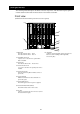
Components
The following illustrationdepicts the blade enclosure components. The illustration depicts optional
modules attached to the blade enclosure that are not included as standard.
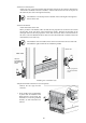
Front view
(When the front bezel and the power unit cover are opened)
1. Blade slot
From the upper left: Slot 1 – Slot 8
From the lower left: Slot 9 – Slot 16
2. CPU blade slot cover
A plate to cover a slot where no optional CPU
blade is installed
3. Power unit
From the left: Power unit 1 - Power unit 6
4. Power unit slot cover
A cover for a slot where no optional power unit is
installed
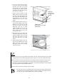
5. Power unit ejector
Turn this ejector and pull the handle to remove a
power unit.
6. Power unit lock
Pull this lock forward to release the lock of a
power unit ejector.
7. Power LED (green)
This LED is green when AC power is supplied.
8. Power STATUS LED (amber)
This LED is amber when an error occurs.
9. Key box
A box to fix and lock the power unit cover (can be
slid toward left and right)
10. Separator
A plate to separate the blade slot into the upper and
lower tier (when installing a full-height blade,
remove this plate)
1
3
6
7
8
5
2
4
9
10