
User guide


23
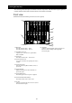
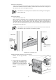
Rear view
1. Fan unit
From the upper left: Fan unit 1 – Fan unit 5
From the lower left: Fan unit 6 – Fan unit 10
2. Fan LED
(green/amber)
This LED is green when the status is normal. When an
error occurs, it is amber.
3. Fan unit ejector
Pull this ejector to remove a fan unit.
4. Switch module slot
From the top left: Slot 1, Slot 2
From the second tier left: Slot 3, Slot 4
From the third tier left: Slot 5, Slot 6
From the bottom left: Slot 7, Slot 8
5. Switch module cover
A cover for a slot where no optional switch module is
installed.
6. EM card
From the left: EM card1, EM card 2
7. EM card slot cover
A cover for a slot where no optional additional EM
card is installed.
8. EM card release lever
Pull this lever forward to remove the EM card.
9. EM tray release lever
Pull this lever forward to remove the EM tray.
*This module should not be removed by anyone
except maintenance staff.
10. AC inlet
A socket to which a power cord is connected
AC inlets correspond to the power units 1 – 6 on the
front side from right
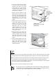
11. Dedicated Management LAN connector (EM
card)
Connected to a network system that supports
10BASE-T/100BASE-TX (auto-negotiation only)
12. SPEED LED (green) (EM card)
Green when the management LAN is operating in
100BASE-TX
13.LINK/ACT LED (green) (EM card)
Green when the management LAN connector is
connected to a network. When there is access, it
flashes green.
14. RESET switch (EM card)
A switch to reboot the EM card
15. STATUS LED (green/amber) (EM card)
Green when the status is normal. When an error
occurs, it is amber.
16.ACTIVE LED (green) (EM card)
Green on the active EM card. Off on the standby EM
card
17.ID LED (blue) (EM Card)
Used to identify EM card
18.Serial (COM) port (EM card)
A port to connect the EM serial console
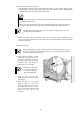
19. ID LED (blue) (the blade enclosure)
Used to identify blade enclosure
20. Power fan vent
Ejects exhaust air from a power fan
21. Power retention tie
A tie to fix a power cord
* These parts may not be installed.
22. Connector for maintenance
* These ports are for maintenance only.
23. Support stay
A plate to separate the switch module slot into the
left and right side.
RST
MNG LAN
ID
Active
M
1
3
4
8
9
10
14
15
16
17
18
19
12
14
17
18
15
16
Close-up of the EM card
2
5
7
11
13
12
13
⑬
⑥
11
20
6
21
8
22
23