
User guide


33
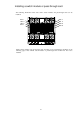
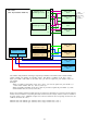
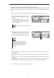
Internal connection between CPU blades and switch modules
If there is no description for the products that support your CPU blades, contact your NEC sales representative to obtain
the latest User's Guide.
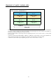
Because switch modules installed on the blade enclosure are shared among CPU blades, any mezzanine card with a different
interface cannot be installed on corresponding CPU blade mezzanine slots. For example, if 4G FC switches are installed on
the switch modules 3 and 4, 1000BASE-T Adapter (2ch) cannot be installed on their corresponding mezzanine slot (for
120Bb-6 and 120Bb-d6, the mezzanine slot 1).
CPU blade
(NEC Express5800/120Bb-6, 120Bb-d6)
Switch module slot 1
Switch module slot 2
Expansion slot 2
(For both type 1 and 2)
Switch module slot 3
Switch module slot 4
Switch module slot 6
Switch module slot 8
Switch module slot 5
Switch module slot 7
Standard interface
(Dedicated to LAN)
When a
mezzanine
card with 4
ports is
installed.
(1)
(2)
Expansion slot1
(Dedicated to
Type 1)
(1)
(2)
(3)
(4)
1
2
(1)
(1)
(1)
(1)
(1)
(1)
(1)
(1)
The numbers with parentheses in the figure represent port numbers of mezzanine cards or switch
modules.
(Switch module port numbers are an example when a CPU blade is installed on the slot 1.
When you install a CPU blade on the other slots, you need to replace the port number of the swi
tch modules.
Examples:
When you install a CPU blade on the slot 2, you need to replace the port number '(1)' of the
switch modules with '(2)'.
When you install a CPU blade on the slot 16, you need to replace the port number '(1)' of th
e switch modules with '(16)'.)