
User guide


42
Important
● The CPU blade blank cover that can be installed on the blade enclosure is N8405-030.
● To install a full-height blade, remove the separator dividing the target blade slots. For safety
reasons, removal of the separator should be done only by sales maintenance personnel.
Contact your sales maintenance personnel to remove the separator.
●To install a half-height blade, a separator should be installed on the target blade slots. The
blade enclosure is shipped with separators installed.
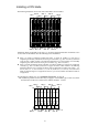
●If one full-height blade is installed on a full-height double-wide block (Slots 1, 2, 9 and 10;
Slots 3, 4, 11, and 12; Slots 5, 6, 13, and 14; or Slots 7, 8, 15, and 16), combine 2 CPU blade
slot covers with screws (screws are shipped with CPU blade slot covers) and attach them to
the blank space of the slots. For information on the blocks, see the illustrations on the
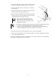
following pages. For information on combining CPU blade slot covers to make a full-height
CPU blade slot cover, see "Assembling a full-height CPU blade slot cover."
● A half-height blade and a full-height blade cannot occupy the same block (Slots 1, 2, 9, and
10; Slots 3, 4, 11, and 12; Slots 5, 6, 13, and 14; and Slots 7, 8, 15, and 16)
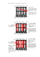
● If more than one 4G FC switch (12 ports) N8406-019 is installed on the blade enclosure,
install CPU blades connected to 4G FC switch modules (12ports) according to the order
(1 3 5 . . . 13 15) shown on the previous page on the upper level of the blade
enclosure. Then, install CPU blades that are not connected to 4G FC switch modules
(12ports) according to the instructions on the previous page. 4G FC switch modules (12
ports) are connected only to the upper level of the blade enclosure.