
User guide


72
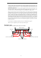
Power connector
Connect the power cords to the AC inlets of the power units installed on the power unit slots 1 and
4 at the rear of the blade enclosure (these units are standard equipment). If any optional power units
are installed on the power unit slots 2, 3, 5, and 6, connect the power cords to the AC inlets of the
optional power units as well.
If the N+N redundant mode is set as the power redundancy mode, power units in the slots 1 to 3
form power system 1 while power units in the slots 4 to 6 form power system 2. Note this when
you connect a device such as a power supply tap or uninterruptible power supply system.
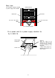
When you connect the power cords to the blade enclosure, use the cable ties that are shipped with
the blade enclosure to fix the power cords to the rack. All power cords should be fixed to the blade
enclosure by cable clamps or to power supply retention ties located near the AC inlets. Cable
clamps or cable ties are shipped with the blade enclosure. For details about installing/removing
power cords with cable clamps, see "Installing cable clamps" and "Removing a power cord form a
cable clamp". Power cords connected to the AC inlets of the power unit slots 1 to 3 should be
routed rightward horizontally and fixed to the rack by cable ties at the rear. Power cords connected
to the AC inlets of the power unit slots 4 to 6 should be routed leftward horizontally and fixed to
the rack by cable ties at the rear. Excessive force should not be applied to a spot where an AC inlet
touches a power cord.
For information on installing an optional power unit, see "Power unit" on page 81.
When AC power is supplied to a power unit, its power LED is green.
Fix to the rack frame.
Fix to the blade enclosure.
Blade enclosure
Rack frame
Overhead view
The illustration depicts four additional power supply units installed.
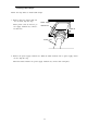
Fix to the rack frame.
Rack frame