N8406-017 4G FCスルーカード ユーザーズガイド 855-900578-A PN# 456-01763-000 2007年 11月 4版 注意 製品のご使用前に、必ず本書をお読みの上で注意をお守り下さい。本書は、必要な時にす ぐ見られるように保管して下さい。 1
注 意 この装置は、情報処理装置等電波障害自主規制協議会(VCCI)の基準に基づくクラスA情報 技術装置です。この装置を家庭環境で使用すると電波妨害を引き起こすことがあります。 この場合には使用者が適切な対策を講ずるよう要求されることがあります。 商標について ESMPROとDianaScopeは日本電気株式会社の登録商標または商標です。 その他、記載の会社名および商品名は各社の登録商標または商標です。 サンプルアプリケーションで使用している名称は、すべて架空のものです。実在する品名、団体名、個人名とは一切 関係ありません。 ご注意 (1) 本書の内容の一部または全部を無断転載することは禁止されています。 (2) 本書の内容に関しては将来予告なしに変更することがあります。 (3) NECの許可なく複製・改変などを行うことはできません。 (4) 本書は内容について万全を期して作成いたしましたが、万一ご不審な点や誤り、記載もれなどお気づ きのことがありましたら、お買い求めの販売店にご連絡ください。 (5) 運用した結果の影響については(4)項にかかわらず責任を負いかねますのでご了承ください。 2
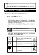
注意 この手引きは、 必要なときすぐに参照できるよう、 お手元に置いておくようにしてください。 「使用上のご注意」を必ずお読みください。本製品の移設の際は必ず本書も一緒にしてくだ さい。 使用上のご注意 - 必ずお読みください - 本製品を安全に正しくご使用になるために必要な情報が記載されています。 安全にかかわる表示について 本製品を安全にお使いいただくために、この手引きの指示に従って操作してください。 この手引きには装置のどこが危険か、どのような危険に遭うか、どうすれば危険を避けら れるかなどについて説明されています。また、装置内で危険が想定される箇所またはその 付近には警告ラベルが貼り付けられています。 手引きおよび警告ラベルでは、危険の程度を表す言葉として、「警告」と「注意」という 用語を使用しています。それぞれの用語は次のような意味を持つものとして定義されてい ます。 死亡又は重傷を負う危険性があることを示します。 火傷やけがの危険性があることを示します。 危険に対する注意・表示は次の3種類の記号を使って表しています。それぞれの記号は次 のような意味を持つものとして定義されています。 注
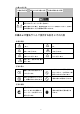
(本書での表示例) 注意を促す記号 危険に対する注意の内容 危険の程度を表す用語 指定以外のコンセントに差し込まない 電源は指定された電圧、電源の壁付きコンセントをお使いください。指定以 外の電源を使うと火災や漏電の原因となります。 本書および警告ラベルで使用する記号とその内容 注意の喚起 感電の危険性があることを示 爆発の危険性があることを示し します。 ます。 指などがはさまれるおそれが 発煙または発火のおそれがある あることを示します。 ことを示します。 高温による傷害を負うおそれ 回転物によるけがのおそれがあ があることを示します。 ることを示します。 特定しない一般的な注意・警告 を示します。 行為の禁止 機器の分解や改造を禁止する ことを示します。 水や液体のかかる場所で使用し ないでください。水に濡らすと感 電や発火のおそれがあります。 ぬれた手で触らないでくださ い。感電のおそれがあります。 一般的な禁止の通告を示します。 行為の強制 電源プラグをコンセントから 抜くこと、および分電盤のサー 一般的な使用者の行動の指示を キットブレーカを切ることの
安全上のご注意 安全のために、ここに記載されている注意事項を守ってください。本装置を取り付けるブ レード収納ユニット(SIGMABLADE-H)には、電源ユニットが搭載されています。感電しな いように注意してください。 一般的な注意事項 人命に関わる業務や高度な信頼性を必要とする業務には使用しない 本装置は、医療機器・原子力設備や機器、航空宇宙機器・輸送設備や機器な ど、人命に関わる設備や機器および高度な信頼性を必要とする設備や機器な どへの組み込みやこれらの機器の制御などを目的とした使用は意図されてお りません。これら設備や機器、制御システムなどに本装置を使用した結果、 人身事故、財産損害などが生じても当社はいかなる責任も負いかねます。 自分で分解・修理・改造はしない 本書に記載されている場合を除き、絶対に分解したり、修理・改造を行った りしないでください。装置が正常に動作しなくなるばかりでなく、感電や火 災の危険があります。 煙や異臭、異音がしたまま使用しない 万一、煙、異臭、異音などが生じた場合は、ただちに電源をOFFにして電源 プラグをコンセントから抜いてください。その後、お買い求めの販売店ま
装置内に水や異物を入れない 装置内に水などの液体、ピンやクリップなどの異物を入れないでください。 火災や感電、故障の原因となります。もし入ってしまったときは、すぐ電源 をOFFにして、ブレード収納ユニットから取り外してください。分解しない で販売店または保守サービス会社にご連絡ください。 中途半端に取り付けない インタフェースケーブルは確実に取り付けてください。ブレード収納ユニッ トには確実に取り付けてください。中途半端に取り付けると接触不良を起こ し、発煙や発火の原因となるおそれがあります。 指定以外のインタフェースケーブルを使用しない インタフェースケーブルは、NECが指定するものを使用し、接続する装置や コネクタを確認した上で接続してください。指定以外のケーブルを使用した り、接続先を誤ったりすると、ショートにより火災を起こすことがあります。 ペットを近づけない 本装置にペットなどの生き物を近づけないでください。排泄物や体毛が装置 内部に入って火災や感電の原因となります。 近くで携帯電話やPHS、ポケットベルを使わない 本装置のそばでは携帯電話やPHS、ポケットベルの電源をOFFにしておいて く
設置・移動・保管に関する注意事項 指定以外の場所に設置しない 本装置を次に示すような場所や本書で指定している場所以外に置かないでく ださい。火災の原因となるおそれがあります。 ● ほこりの多い場所。 ● 給湯器のそばなど湿気の多い場所。 ● 直射日光が当たる場所。● 不安定な場所。 腐食性ガスの存在する環境で使用または保管しない 腐食性ガス(二酸化硫黄、硫化水素、二酸化窒素、塩素、アンモニア、オゾン など)の存在する環境に設置し、使用しないでください。また、ほこりや空気 中に腐食を促進する成分(塩化ナトリウムや硫黄など)や導電性の金属などが 含まれている環境へも設置しないでください。装置内部のプリント板が腐食 し、故障および発煙・発火の原因となるおそれがあります。もしご使用の環 境で上記の疑いがある場合は、販売店または保守サービス会社にご相談くだ さい。 通気口をふさがない ブレード収納ユニットにある通気口をふさがないでください。ブレード収納 ユニットに搭載した機器の内部の温度が上がり、火災の原因となるおそれが あります。 故障時の処置 故障時の処置 故障した場合は、分電盤のブレーカを切断し、ま
お手入れ・内蔵機器の取り扱いに関する注意事項 ブレード収納ユニット内部に手を入れない ブレード収納ユニットに装置を取り付け/取り外しをする際には、ブレード 収納ユニット内に手を入れないでください。感電するおそれがあります。ま た、ブレード収納ユニットに取り付けられているカバーは装置の取り付けな ど必要な場合を除いて取り外さないでください。装置の取り付け/取り外し は1台ずつ行ってください。 ブレード収納ユニットに取り付けたまま取り扱わない お手入れをする場合は、ブレード収納ユニットから取り外してから行ってく ださい。たとえ電源をOFFにしても、ブレード収納ユニットに接続したまま 作業するとブレード収納ユニットに搭載されている機器が正常に動作しなく なるばかりか感電や火災の原因となるおそれがあります。 また、電源プラグはときどき抜いて、乾いた布でほこりやゴミをよくふき取 ってください。ほこりがたまったままで、水滴などが付くと発熱し、火災の 原因となるおそれがあります。 8
取り扱い上のご注意 - 装置を正しく動作させるために 本装置を正しく動作させるために次に示す注意事項をお守りください。これらの注意を無 視した取り扱いをすると装置の誤動作や故障の原因となります。 保守サービスについて 本製品の保守に関して専門的な知識を持つ保守員による診断・保守サービスを用意してい ます。 本製品をいつまでもよい状態でお使いになるためにも、保守サービス会社と保守サービス を契約されることをお勧めします。 ● スイッチモジュール/スルーカード - 本装置は近接制限区域に設置してください。 - 本装置を取り付けることができるブレード収納ユニットに搭載してください。 - スイッチモジュール/スルーカードはブレード収納ユニットに必ず正しく取り付 け直してください。 - 落雷等が原因で瞬間的に電圧が低下することがあります。この対策として無停電電 源装置等を使用することをお勧めします。 ● オプションの増設電源およびその他電子部品 - これらの製品は大変静電気に弱い電子部品です。身体の静電気を逃がしてから製品 を取り扱ってください。また、製品の端子部分や部品を素手で触ったり、製品を直 接机の
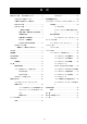
目 次 使用上のご注意 - 必ずお読みください - ................... 3 FCコネクタ......................................... 27 安全にかかわる表示について ........................... 3 緊急電源遮断(EPO) .................................................... 29 本書および警告ラベルで使用する コマンドラインインタフェース(CLI) (EMカード) ..... 30 記号とその内容 ................................................ 4 初期設定 ......................................................... 30 安全上のご注意 ................................................ 5 ユーザに対する 一般的な注意事項 .................................
まえがき この度は、N8406-017 4G FCスルーカードをお買い上げいただき誠にありがとうござい ます。 本装置はブレード収納ユニット(SIGMABLADE-H)に搭載することにより、各CPUブレード に取り付けたブレード用メザニンカード(FibreChannelコントローラ)を外部接続する機能 を実現させます。 本装置をご使用になる前に、必ず本書をお読みください。なお、SIGMABLADEシリーズ に添付の「ユーザーズガイド」または「スタートアップガイド」も併せて参照してくださ い。 装置概要 本装置は、ブレード収納ユニットに搭載される最大で16台のCPUブレードと接続すること により、各CPUブレードのメザニン拡張スロットに搭載したブレード用メザニンカード(F ibreChannelコントローラ)のポートを外部接続することができます。 添付品の確認 製品が入った梱包箱の中には、本体以外にいろいろな添付品が入っています。以下の構成 品表を参照してすべてがそろっていることを確認し、それぞれ点検してください。万一足 りないものや損傷しているものがある場合は、販売店に連絡してください。 品名 1 4G
各部の名称 本装置の各部の名称を次に示します。 装置前面 ① 1-4 ID 1 2 3 4 ② 5 6 7 8 5-8 9 10 11 12 STATUSラ IDラン ンプ プ ③ ④ 13 14 15 16 ⑤ 通信ポー ① 通信ポート ト 上段左からポート13~ポート16。 下段左からポート1~ポート12。 ② イジェクタ このイジェクタを手前に引くことで本装置を ブレード収納ユニットから取り外すことがで きる。 ③ IDランプ(青色) スイッチモジュール/スルーカードの筐体識 別に使用する。 ④ STATUSランプ(緑色/アンバー色) 正常状態の場合は緑色に点灯する。異常の場合 はアンバー色に点灯する。 ⑤ LINK/ACTランプ(緑色) 通信ポートがネットワークに接続されている 場合は緑色に点灯する。 12 13-16 9-12
設 置 構成品の確認 11ページの構成品表で、構成品がそろっていることを確認してください。 ブレード収納ユニットへの取り付け ● 本装置を取り付けることのできるブレード収納ユニットはブレード収納ユニット (SIGMABLADE-H)です。 ● スイッチモジュール/スルーカードは種類および組合せによって搭載可能なスイッ チモジュールスロットが異なりますので、注意してください。 ブレード収納ユニット(SIGMABLADE-H)の搭載スロットの位置については下図のとおり です。 スロット スロット 1 スロット 3 スロット 5 7 1-4 1-4 1-4 ID 1 2 3 4 5 6 7 8 5-8 9 10 11 12 13 14 15 16 13-16 9-12 1-4 ID 1 2 3 4 5 6 7 8 5-8 9 10 11 12 13 14 15 16 13-16 9-12 1-4 ID 1 2 3 4 5 6 7 8 5-8 9 10 11 12 13 14 15 16 13-16 9-12 1-4 ID 1 2 3 4 5 6
は、ブレード収納ユニットのユーザーズガイドを参照してください。 14
4G FCスルーカードとFibreChannelコントローラ間のFCコネクタ接続 図 FCポート(16ポート) FCポート(16ポート) 4G FCスルーカード2 4G FCスルーカード1 Port2 Port1 Port1 Port2 ・・・ 最大16台 コ ン ト ロ ー ラ Port2 Port1 Port2 FC コ ン ト ロ ー ラ FC 2/4Gbps FC FC コ ン ト ロ ー ラ Port1 コ ン ト ロ ー ラ CPUブレード ブレード収納ユニット(SIGMABLADE-H) ※本装置の通信ポート1~16は、それぞれブレード収納ユニットのブレードスロッ ト1~16に搭載されたCPUブレードのブレード用メザニンカード(FibreChannel コントローラ)に対応します。本装置の通信ポートについては「各部の名称」を、 ブレードスロットについてはブレード収納ユニットのユーザーズガイドを参照 してください。 ● メザニン拡張スロットを利用して本装置をCPUブレードに接続する場合は、使用す るメザニン拡張スロット数に応じた枚数のブレード用メザニ
取り付け手順 ブレード収納ユニットに本装置を取り付けます。本装置はブレード収納ユニットの電源が ONの状態(他のスロットのCPUブレードおよびスイッチモジュール/スルーカードが動作 している状態)でも取り付け/取り外しができます。(取り付けの一例を示します。他のス ロットへも同様の手順で取り付けられます。) 装置を安全にお使いいただくために次の注意事項を必ずお守りください。人 が死亡する、または重傷を負うおそれがあります。詳しくは、3ページ以降の 説明をご覧ください。 ● 複数のスイッチモジュール/スルーカードを同時に取り付け/取り外し しない ● ブレード収納ユニット内部に手を入れない ブレード収納ユニットをラックから取り出して、CPUブレード、スイッチモ ジュール、スルーカード、またはその他のオプションを取り付けたりしない でください。 1. 「ブレード収納ユニットへの取り付け」(13ページ)を参照して、取り付けるスロットを 確認する。 2.
4. 本装置のイジェクタ面を上にして装置 左右をしっかりと持ち、ゆっくりとて いねいにブレード収納ユニットに半 分(約20cm)ほど差し込む。 ② イジェクタを持たないでください。 ① イジェクタが曲がって装置が破損し てしまうおそれがあります。 5. イジェクタを完全に開いた状態にして、装置前面のフレーム部分を指で押し、ブレード 収納ユニットの奥まで装置をゆっくりとていねいに差し込む。 装置前面をゆっくりとていねいに押し、ブレード収納ユニットの奥まで差し込まれるとイ ジェクタが少し閉じます。そこまでゆっくりと押してください。 6.
取り外し手順 本装置の取り外しは、次のとおりです。 1. 本装置にインタフェースケーブルが接続されている場合は、すべてのケーブルを取り外 す。 2. イジェクタを開く。(イジェクタを開け ① る際は、イジェクタを固定しているスト ッ パ を右 に 押し な がら開 け てく だ さ い。) ② イジェクタは止まるまで完 全に開いてください。 3. イジェクタを持って装置のフレームの 左右を手で持てるくらい(約10cm)まで ブレード収納ユニットから引き出す。 重 イジェクタ部分を持って取り外さな いでください。イジェクタが外れて装 置を落下させたり、イジェクタが曲が って装置が破損してしまうおそれが あります。 4. 装置のフレームの左右をしっかりと持って、ブレード収納ユニットから取り出す。 本装置を取り外したまま運用する場合は、ブランクパネルを取り付けてください。 5.
SFPモジュールの取り付け 装置を安全にお使いいただくために次の注意事項を必ずお守りください。人 が死亡する、または重傷を負うおそれがあります。詳しくは、3ページ以降の 説明をご覧ください。 ● 光線を直視しない 本装置に添付のSFPモジュールは、レーザ安全基準クラス1に適合してい ますが、近距離(20cm以内)での直視は瞳孔に悪影響を与える恐れがあ ります。動作中はSFPモジュールのポートをのぞきこまないでください。 また、光ファイバケーブルを接続していない場合は必ず防塵カバー(ゴム キャップ)をはめ、コネクタ端子保護してください。 取り付け手順 SFPモジュールの本製品への実装時は通信ポートの奥まで差し込んでください。 N8406-017 4G FCスルーカード SFPモジュール 通信ポート 本装置に添付または指定製品以外のSFPモジュールはご利用になれません。 21
取り外し手順 SFPモジュールのレバー(引き抜き金具)を下ろしてください。 N8406-017 4G FCスルーカード SFPモジュール レバーをつまんで図中の矢印方向に引き抜いてください。 N8406-017 4G FCスルーカード SFPモジュール取外し時は必ずレバーを下ろし作業を実施してくださ い。レバーを下げずにSFPモジュールを引き抜いた場合、SFPモジュー ルの破損、通信ポートの破損等が発生する場合があります。 光ファイバケーブルの取り付けについては、ケーブルフォーミングや取 り扱う上での専門知識が必要です。専門知識を持った方が行ってくださ い。 23
電源のON/OFF スイッチモジュール/スルーカードの電源ON/OFF ブレード収納ユニットに搭載されているスイッチモジュール/スルーカードの電源のON/ OFFには次の2つの方法があります。ビデオモニタおよび接続している周辺機器をONにし てからそれぞれの方法で電源をONにしてください。スイッチモジュール/スルーカード の電源ON後の動作・確認等は「コマンドラインインタフェース」の「動作状態の確認」 を参照してください。 ブレード収納ユニットからの電源ON ラックの電源ONによりブレード収納ユニットに電源の供給が始まると、自動的にブレー ド収納ユニットに搭載されているスイッチモジュール/スルーカードの電源がONになり ます。また、ブレード収納ユニットに電源が供給された状態でスイッチモジュール/スル ーカードの交換を行った場合も、スイッチモジュール/スルーカードの交換後、自動的に スイッチモジュール/スルーカードの電源がONになります。(ブレード収納ユニットの電 源ONの方法はブレード収納ユニットのユーザーズガイドを参照してください。) ネットワーク・シリアル(COM)ポートからの電源ON/OFF ブレー
CLIからのスイッチモジュール/スルーカードの電源ONの方法は以下のとおりです。 1. EMカードの電源がONになっていることを確認する。 2. EMシリアルコンソールまたはEMコンソールのCLIから”Administrator”またはアクセス 権がADMINISTRATORかOPERATORであるユーザでログインしていることを確認す る。(ログインしていない場合は、”Administrator”またはアクセス権がADMINISTRATO RかOPERATORであるユーザでログインしてください。) 3. CLIより以下のコマンドを実行する。 (詳しくは「コマンド仕様」を参照してください。) ― 電源投入 指定したスイッチモジュール/スルーカードの電源を投入する。 POWERON SWITCH <スロット番号> 以上で完了です。 CLIからのスイッチモジュール/スルーカードの電源OFFの方法は以下のとおりです。 1. EMカードの電源がONになっていることを確認する。 2.
また、CLIからのスイッチモジュール/スルーカードの再起動の方法は以下のとおりです。 1. EMカードの電源がONになっていることを確認する。 2. EMシリアルコンソールまたはEMコンソールのCLIから”Administrator”またはアクセス 権がADMINISTRATORかOPERATORであるユーザでログインしていることを確認す る。(ログインしていない場合は、”Administrator”またはアクセス権がADMINISTRATO RかOPERATORであるユーザでログインしてください。) 3.
ケーブルの接続 本製品は4Gbpsまたは2Gbps用です。1Gbps製品を接続しないよう注意願い ます。 前面 FCコネクタ 本装置の通信ポートに搭載したSFPモジュールのFCコネクタにFCケーブルを接続し、iSt orage等のストレージ装置を接続することができます。詳しくは接続装置の説明書等を参 照してください。 PC ESMPRO/S M 1-4 ID 1 2 3 4 5 6 7 8 5-8 9 10 11 12 13 14 15 16 ID 13-16 1-4 9-12 1 2 3 4 5 6 7 8 5-8 9 10 11 12 13 14 15 16 13-16 9-12 iStorage ブレード収納ユニッ ト (FCスイッチ) 27 DianaScopeMg
SFPポートをお使いになる場合 以下の点にご注意ください。 光ファイバケーブルの取り付けについては、ケーブルフォーミングや取 り扱う上での専門知識が必要です。専門知識を持った方が行ってくださ い。 光ファイバケーブルは慎重かつ丁寧に扱うよう注意してください。 光ファイバケーブルの曲げ半径は「最低でも50mm」は確保してくださ い。 ケーブルのコネクタは無理に押し込まないでください、各コネクタは正 しい向き、正しい角度で差し込まないと接続できません。 正しく差し込んだ時は強い力を入れなくてもスムーズに差し込めるよう になっています。うまく差し込めないときには無理矢理差し込まずにも う一度コネクタの向きを確認してください。 ケーブル装着時にコネクタ及びコンタクトに座曲等の損傷、ゴミの付着、 汚れのないことを確認してください。 誤配線のないようにケーブルの仕様と接続先のコネクタを確認してくだ さい。 コネクタを床などに落下させ破損させないように取り扱いに注意してく ださい。また、コネクタを床上に引きずりゴミなどを付着させないよう にしてください。
緊急電源遮断(EPO) 環境異常(火災・地震)の発生時、コンピュータの入力電源、無停電電源装置(UPS)の電源、 空調機などの電源を緊急電源遮断(EPO:Emergency Power Off)させ、二次災害を防ぐ必要 があります。装置の電源を緊急に遮断する必要があるような危険が生じた場合には、ブレ ード収納ユニットのユーザーズガイドを参照してEPOを行ってください。 なお、EPOを行った場合、データが壊れる場合があります。したがって、どのような場合 にEPOを行うかを明確に定め、その条件や作業内容を周知徹底して運用してください。 29
コマンドラインインタフェース(CLI) (EMカード) EMカードのコマンドラインインタフェース(CLI)により、ブレード収納ユニットに搭載さ れているCPUブレードやスイッチモジュールなどの搭載モジュールおよびネットワーク の設定・管理等を行うことができます。 CLIはEMシリアルコンソールおよびEMコンソールから利用できます。CLI、EMシリアル コンソールおよびEMコンソールについては、ブレード収納ユニットのユーザーズガイド を参照してください。 初期設定 EMシリアルコンソールまたはEMコンソールから、ブレード収納ユニットに搭載されたス イッチモジュール/スルーカードの初期設定を行います。設定方法はブレード収納ユニッ トのユーザーズガイドを参照してください。(「ユーザに対するアクセス権の設定」、「E Mカードの設定確認およびバックアップ・リストア(EMカード)」 ユーザに対するモジュールアクセス権の設定(EMカード) 1. EMカードの電源がONになっていることを確認する。 2.
4. CLIより以下のコマンドを実行して設定項目が反映されていることを確認する。 設定したユーザからモジュールのIDランプのON/OFF操作を行う。(操作は「コマ ンド一覧」を参照してください。) ― モジュールのIDランプのON/OFF ユーザのスイッチモジュール/スルーカードのIDランプのON/OFFを行う。 (あらかじめ、設定する対象モジュールのスロット番号を確認してください) SET SWITCH UID <スロット番号> [ON | OFF] 以上で完了です。 動作状態の確認 ブレード収納ユニットおよびブレード収納ユニットに搭載されるモジュールの動作状態 を確認します。動作状態の確認はEMシリアルコンソールまたはEMコンソールのCLIから 行います。 スイッチモジュール/スルーカード 1. EMカードの電源がONになっていることを確認する。 2. EMシリアルコンソールまたはEMコンソールのCLIにログインしていることを確 認する。(ログインしていない場合はログインしてください。) 3.
以上で完了です。 32
モジュールの交換 装置を安全にお使いいただくために次の注意事項を必ずお守りください。人 が死亡する、または重傷を負うおそれがあります。詳しくは、3ページ以降の 説明をご覧ください。 ● 複数のCPUブレード、スイッチモジュール/スルーカード、EMカード、 FANユニット、電源ユニット、またはその他モジュールを同時に交換しな い ● ブレード収納ユニット内部に手を入れない スイッチモジュール/スルーカード スイッチモジュール/スルーカードを交換します。スイッチモジュール/スルーカードは ブレード収納ユニットの電源がONの状態(他のスロットのCPUブレードおよびスイッチモ ジュール/スルーカードが動作している状態)でも交換することができます。 1.
4. 交換するスイッチモジュールスロットに本装置を取り付ける。(本装置の取り付け方は 「取り付け手順」を参照してください。) 取り付けた後自動で電源がONにならない場合は、以下のコマンドを実行して本装置 の電源をONにする。 (1) EMカードの電源がONになっていることを確認する。 (2) EMシリアルコンソールまたはEMコンソールのCLIから”Administrator”またはア クセス権がADMINISTRATORかOPERATORであるユーザでログインしている ことを確認する。(ログインしていない場合は、”Administrator”またはアクセス権 がADMINISTRATORかOPERATORであるユーザでログインしてください。) (3) CLIより以下のコマンドを実行する。(詳しくは「コマンド仕様」を参照してくだ さい。) ― 電源投入 指定したスイッチモジュール/スルーカードの電源を投入する。 POWERON SWITCH <スロット番号> 5.
~ Memo ~ 35
コマンド一覧 コマンド一覧 SIGMABLADE-H EM ファームウェアでサポートする CLI コマンドの一覧を下表に示す。 「アクセス権」の意味 A: Administrator による操作が可能であることを意味する。 O: Operator による操作が可能であることを意味する。 U: User による操作が可能であることを意味する。 「EM カードのアクティブ/スタンバイ」の意味 A:アクティブ EM(現用系)からの設定が可能であることを意味する。 S:スタンバイ EM(待機系)からの設定が可能であることを意味する。 「バックアップ対象」の意味 ○:Config 情報でのバックアップ対象であることを意味する。 -:Config 情報でのバックアップ対象でないことを意味する。 SIGMABLADE-H EMファームウェア CLIコマンド一覧 コマンド アクセ 説明 初期値 ス権 EMカード バッ の クア アクティブ ップ / 対象 スタンバイ スイッチモジュール管理コマンド POWEROFF A/O SWITCH POWERON A/O A/O A/O A/O
コマンド アクセ 説明 初期値 ス権 EMカード バッ の クア アクティブ ップ / 対象 スタンバイ 表示項目: スイッチモジュールタイプ 製造者名 製品名 製品パーツ番号 製品バージョン 製品シリアル番号 SHOW SWITCH A/O/U LIST 搭載されているスイッチモジュ N/A A - N/A A - N/A A - ールの一覧を表示する。 SHOW SWITCH A/O/U PORT MAP 指定されたスイッチモジュール のポートマッピング情報(E-Keyi ng情報)を表示する。 SHOW SWITCH STATUS A/O/U スイッチモジュールの稼動ステ ータスを表示する。 表示項目: IDランプ状態 稼動ステータス ※ 「表示項目」は表示される主要な項目を記載したものです。 37 備考
コマンド仕様 スイッチモジュール管理コマンド ※ 「表示項目」は表示される主要な項目を記載したものです。 スイッチモジュールの電源OFF 概要 指定したスイッチモジュールの DC 電源を切断(OFF)する。 コマンド名 POWEROFF SWITCH 引数 <スイッチモジュール番号> | <スイッチモジュール番号> - <スイッチモジュール番号> | <スイッチモジュール番号> , <スイッチモジュール番号> | "ALL" <スイッチモジュール番号>と<スイッチモジュール番号>を’-‘(ハイフン)または‘,‘(カンマ)で 連結する場合、’-‘(ハイフン)または‘,‘(カンマ)の前後にスペースを挿入すること。 実行例 1Z34AB7890(Administrator)> poweroff switch 1 Powering off switch module 1.
実行例 1Z34AB7890(Administrator)> poweron switch 1 Powering on switch module 1. 1Z34AB7890(Administrator)> スイッチモジュール電源ONコマンド実行例 初期値 補足 スイッチモジュールの再起動 概要 指定したスイッチモジュールを再起動する。 コマンド名 RESTART SWITCH 引数 <スイッチモジュール番号> 実行例 1Z34AB7890(Administrator)> restart switch 4 Entering anything other than 'YES' will result in the command not executing. Are you sure you want to restart the Switch Module? YES Resetting Switch Module in slot 4.
第二引数 32 文字以内の半角英数字と一部記号で指定する。 実行例 1Z34AB7890(Administrator)> set switch name 1 Switch1 Changed the user assigned name for Switch Module #1 to "Switch1".
IP アドレス ファームウェアバージョン など コマンド名 SHOW SWITCH INFO 引数 <スイッチモジュール番号> | <スイッチモジュール番号> - <スイッチモジュール番号> | <スイッチモジュール番号> , <スイッチモジュール番号> | "ALL" <スイッチモジュール番号>と<スイッチモジュール番号>を’-‘(ハイフン)または‘,‘(カンマ)で 連結する場合、’-‘(ハイフン)または‘,‘(カンマ)の前後にスペースを挿入すること。 実行例 1Z34AB7890(Administrator)> show switch info 5 5.
ID ランプ状態 コマンド名 SHOW SWITCH LIST 引数 なし 実行例 1Z34AB7890(Administrator)> show switch list Slot Switch Type Manufacturer Power ---- ----------------- -------------------- ----1 [Absent] 2 [Absent] 3 Ethernet NEC Off 4 [Absent] 5 Fibre Channel NEC On 6 [Absent] 7 [Absent] 8 [Absent] Totals: 2 switch modules installed, 1 powered on.
実行例 > show switch port map all Status -----8: Size ---- Technology Product Name ---------- ------------ 7: 6: 5: OK Port Status Blade Mezz/Nic Port Single 1 2 3 PCIe 4 5 6 Single 1 2 3 4 7 Virtual I/O Switch 8 9 10 11 12 13 14 15 16 OK OK 9 10 2 2 1 1 4: 3: 2: 1: OK Port Status Blade Mezz/Nic Port Ethernet 5 6 7 8 1Gb Intelligent L2 Switch 9 10 11 12 13 14 15 16 OK 10 NI 1 1Z34AB7890(Administrator)> スイッチモジュール ポートマップ情報(E-Keying情報)表示コマンド実行例 初
スイッチモジュール ステータスの表示 概要 スイッチモジュールの稼動ステータスを表示する。 表示項目 稼動状態 温度状態 スイッチモジュール上の CPU 状態 STATUS ランプ状態 ID ランプ状態 電源状態 スイッチモジュールの消費電力(最大消費電力) スイッチモジュールの消費電力(待機時消費電力) E-FUSE 状態 コマンド名 SHOW SWITCH STATUS 引数 <スイッチモジュール番号> | <スイッチモジュール番号> - <スイッチモジュール番号> | <スイッチモジュール番号> , <スイッチモジュール番号> | "ALL" <スイッチモジュール番号>と<スイッチモジュール番号>を’-‘(ハイフン)または‘,‘(カンマ)で 連結する場合、’-‘(ハイフン)または‘,‘(カンマ)の前後にスペースを挿入すること。 44
実行例 1Z34AB7890(Administrator)> show switch status 1 Switch Module #1 Information: Status : OK Thermal : OK CPU Fault : OK Health LED : OK ID LED : Off Powered : On Power On Watts : 48 Power Off Watts : 5 E-FUSE Status : OK Diagnostic Status: Internal Data Management Processor Thermal Warning Thermal Danger I/O Configuration Power Device Failure Device Degraded OK OK OK OK Not Performed Not Performed OK OK 1Z34AB7890(Administrator)> スイッチモジュールステータス表示実行例 初期値 補足 Diagnostic Status について Internal Data FRU情報の正当性
異常時の処置 本章ではスイッチモジュール/スルーカードを中心に異常が発生した場合の一般的な解 決策について説明しています。 電源 ラックのスイッチをONにしても、スイッチモジュール/スルーカードのSTATUSランプ が緑色に点灯しない。 • 無停電電源装置(UPS)等の電源制御装置のスイッチが入っているかを確認してください。 • 分電盤のスイッチが入っているかを確認してください。 • ブレード収納ユニットに電源ケーブルが確実に接続されているかを確認してください。 • ブレード収納ユニットの電源ケーブルが電源タップに確実に接続されているかを確認 してください。 • 電源タップのケーブルが無停電電源装置(UPS)に確実に搭載されているかを確認してく ださい。 • 電源ユニットがブレード収納ユニットに確実に搭載されているかを確認してください。 • ブレード収納ユニットに搭載されている電源ユニットの台数が適切かを確認してくだ さい。 • ブレード収納ユニットに設定されている電源の冗長モードが適切かを確認してくださ い。 • スイッチモジュール/スルーカードがブレード収納ユニットに確実に搭載されている かを確認してく
廃 棄 装置の廃棄、回収又はリサイクル時は事前に当社営業にご連絡願います。 第三者への譲渡について 本装置または、本装置に添付されているものを第三者に譲渡(または売却)するときは、次 の注意を守ってください。 ● 本体について 本装置を第三者へ譲渡(または売却)する場合には、本書を一緒にお渡しください。 ● 添付のソフトウェアについて 本装置に添付のソフトウェアを第三者に譲渡(売却)する場合には、以下の条件を満た す必要があります。 - 添付されているすべてのものを譲渡し、譲渡した側は一切の複製物を保持しないこ と - 各ソフトウェアに添付されている『ソフトウェアのご使用条件』の譲渡、移転に関 する条件を 満たすこと - 譲渡、移転が認められていないソフトウェアについては、インストールした装置か ら削除した 後、譲渡すること 仕 様 モデル 4G FCスルーカード 型番 N8406-017 インタフェース 通信ポート(SFPコネクタ) 16ポート サイズ(W×D×H) 390mm×290mm×30mm(突起物を含む) 最大消費電力 30W 質量 1.
レーザ製品の取り扱い 本装置には、JIS C6802、EN60825、IEC825及びFDA21CFR chapter1 subchapter Jに基づくクラス 1 レ-ザ製品が使用されています。 注)クラス 1レーザは、JIC6802、EN60825、IEC825及びFDA 21CFRでは、被爆したとしても人体 に悪影響の無いレベルのレーザと定義されています。以下のラベルが装置の表面に貼られていま す。 クラス 1 レ-ザ製品 CLASS 1 LASER PRODUCT PER IEC825 LASER KLASSE 1 NACH IEC825 PRODUCTO LASER DE CLASE 1 Complies with 21CFR chapter 1, Subchapter J 電源の瞬時電圧低下対策について 本装置は、落雷等による電源の瞬時電圧低下に対し不都合が生じることがあります。電源の瞬時電圧 低下対策としては、交流無停電電源装置(UPS)等を使用されることをお勧めします。 48
お客様へ:本製品の販売元、営業等に事故発生時の緊急連絡先の記入をご依頼下さい。 緊急連絡先 TEL: FAX: 所在地: N8406-017 4G FCスルーカード ユーザーズガイド 2007 年 11月 4版 日 本 電 気 株 式 会 社 東京都港区芝五丁目7 番1 号 TEL(03)3454-1111 (大代表) 本書は再生紙を使用しています。 乱丁・落丁はお取り替えします。 © NEC Corporation 2006, 2007, © Hewlett-Packard Development Company, L.P.
2006 日本電気株式会社の許可なく複製・改変などを行うことはできません。 50
<保護用紙> 51
N8406-017 FC Pass-Through Card User‟s Guide 855-900578-A 2007 Nov. 4th Edition Note Read this guide carefully before using this product. Keep this guide handy for quick reference when necessary.
FCC COMPLIANCE This product has been tested and found to comply with the limits for a Class A digital device, pursuant to Part 15 of the FCC rules. These limits are designed to provide reasonable protection against harmful interface when the device is operated in a commercial environment. This device generates, uses and can radiated radio frequency energy and if not installed and used in accordance with the instruction manual, may cause harmful interference to radio communications.
damage arising from the use of this manual regardless of (4) above.
Note Keep this User‟s Guide handy for quick reference when necessary. Make sure to read “Notes for safety handling.” When you relocate the product, make sure to take this guide with the product. Notes for safety handling This section provides information for using the product safely. SAFETY INIDICATIONS To use this product safely, follow the instructions in this User‟s Guide.
Symbols and their descriptions used in this User’s Guide and warning labels are as follows: Attention Indicates the risk of electric shock. Indicates the risk of explosion. Indicates that improper use may cause fingers to be caught. Indicates the risk of smoke emission or fire. Indicates that improper use may cause personal injury. Indicates that improper use may cause personal injury due to moving fan blades. Indicates a general notice or warning that cannot be specifically identified.
Precautions for safety Observe the precautions for safety described in this section. The Blade Enclosure (SIGMABLADE-H) in which this card is installed has power units. Handle them carefully to avoid electric shock. . General precautions WARNING Do not use this product for services where critical high availability may directly affect human lives.
CAUTION Prevent water or foreign objects from getting into the product. Do not let water or foreign objects (e.g., pins or paper clips) enter the product. There is a risk of fire, electric shock, and malfunction. When such things accidentally enter the server, immediately turn off the power and unplug the cords. Contact your sales representative. Do not disassemble the product. Connect firmly Connect interface cables securely. Install the card securely in the Blade Enclosure.
Installation, relocation and storage WARNING Do not install the product in a place other than specified. Do not install the product in a place other than specified in this guide. Avoid the following locations. There is a risk of fire. ● dusty place ● a humid place located near a boiler, etc. ● a place exposed to direct sunlight ● an unstable place Do not use or store this product in a corrosive environment.
Maintenance, cleaning and handling of internal product WARNING Do not place your hands inside the Blade Enclosure. When you install or remove the product from the Blade Enclosure, do not place your hands inside the Blade Enclosure. There is a risk of electric shock. The cover attached to the Blade Enclosure should not be removed unless required. Only one product should be installed or removed at a time. CAUTION Do not handle the product while it is installed in the Blade Enclosure.
Handling precautions to use the card correctly Observe the following precautions to use this card correctly. Failure to observe the precautions can result in malfunction or mechanical error. About maintenance services Hint Diagnostic and maintenance services by personnel with expertise on maintenance of this product are available. To keep this product in good condition, it is recommended to purchase maintenance services from the maintenance service provider.
Table of Contents Notes for safety handling .............. 55 Connecting cables..................... 65 SAFETY INIDICATIONS ............. 55 Front view ......................... 65 Symbols and their descriptions used in t FC connector ................. 65 his User’s Guide and warning labels are Emergency power off (EPO) ........... 67 as follows: ......................... 56 Command line interface (CLI) (EM card) 68 Precautions for safety ............... 57 Initial settings.......................
Preface Thank you for purchasing the N8406-017 FC Pass-Through Card. This card allows mezzanine cards (FibreChannel controller) installed in CPU blades in the Blade Enclosure (SIGMABLADE-H) to connect to an external network. Make sure to read this guide before using the card. Refer to the User‟s Guide or startup guide that is shipped with the SIGMABLADE series as well.
Components The following diagram describes the card components: Front view 1 1-4 ID 1 2 3 4 2 5 6 7 8 5-8 9 10 11 12 13 14 15 16 STATUSラ IDラン ンプ プ 3 4 5 通信ポー 1. Communication port From top-left: Port 13 to 16 From bottom-left: Port 1 to 12 ト 2. Ejector Pull the ejector forward to remove the card from the Blade Enclosure. 3. ID LED (blue) This LED is used to identify the switch module/pass-through card. 4.
Installation Checking components See the list on page 54 to ensure that you have all the accessories. Installation of the card in a Blade Enclosure Important ●SIGMABLADE-H is the Blade Enclosure in which this card can be installed. ● Note that a switch module slot in which a switch module or pass-through card can be installed depends on the type of the switch module/pass-through card and how other switch modules and/or pass-through cards are installed.
Connection of FC connectors: between FC Pass-Through Cards and FibreChannels FC ports (16 ports) FC ports (16 ports) FC Pass-Through Card 2 FC Pass-Through Card 1 2/4Gbps Port2 Port1 Port1 Port2 Port1 Port1 Port2 FC Controller Up to 16 units FC Controller FC Controller FC Controller ・・・ Port2 CPU blade Blade enclosure (SIGMABLADE-H) The communication ports 1 to 16 of this card correspond to mezzanine cards for the CPU blades installed in the blade slots 1 to 16 of the Blade Enclosure.
Installing the card Follow the steps below to install the card in the Blade Enclosure. The card can be installed/removed even if the Blade Enclosure is powered on (i.e., switch modules/pass-through cards in other slots are working). An example of installation is provided. Follow the same steps for installation in other slots. WARNING Make sure to follow the instructions and notes to use the card safely. There is a risk of death or serious injury. For more information, see the descriptions from page 55.
4. Hold the both sides of the card with its ejector side facing the top and slowly insert the card halfway into the Blade Enclosure (approximately 20 cm). (2) Important Do not hold the ejector. Otherwise the ejector might be distorted, damaging the card. 5. (1) Insert the card slowly into the Blade Enclosure by pressing the frame of the card front with your thumbs with the ejector fully opened.
Removing the card Follow the steps below to remove the card: 1. If any interface cables are connected to the card, remove them. 2. Open the ejector. When you open the ejector, press the stopper securing the ejector rightward. Check Fully open the ejector until it stops. (1) (2) 3. Hold the ejector and pull the card out of the Blade Enclosure until you can hold the card frame with both of your hands (approximately 10 cm). 4. Important Do not hold the ejector.
Installation of SFP modules WARNING Make sure to follow the instructions below to use the card safely. There is a risk of death or serious injury. For more information, see the descriptions from page 55. ● Do not look directly at the laser The SFP modules shipped with this product are classified as a CLASS 1 LASER PRODUCT. However, looking at them within a distance of 20 cm may damage your eyesight. Do not look into SFP module ports during system operation.
Removing an SFP module Pull down the lever (metal part for removing SFP module) of the SFP module. N8406-017 FC Pass-Through Card SFP module Pull down this way Pull the lever toward the direction indicated by the arrow in the illustration. N8406-017 FC Pass-Through Card Pull this way Important When you remove an SFP module, make sure to pull down its lever. If you pull the SFP module without pulling down its lever, the module or the communication port may be damaged.
Powering on and off Powering on and off switch modules and pass-through cards Switch modules and pass-through cards installed in the Blade Enclosure can be powered on and off in one of two ways. Power on connected peripheral equipment first and then power on the modules and/or pass-through cards. For information on status or confirmation after switch modules and/or pass-through cards are powered on, see “Checking operations” in “Command line interface (CLI) (EM card).
Follow the instructions below to power off a switch module or pass-through card by using the CLI: 1. Check that the EM card is powered on. 2. Connect to the CLI of the EM card and log in as “Administrator” or with the access rights of an ADMINISTRATOR or OPERATOR. 3. Enter the following command. For details, see “Command specifications.
Connecting cables Important Note that this card supports only 4Gbps or 2Gbps. Do not connect a card which only supports 1Gbps. Front view FC connector You can connect an FC cable via an SFP module installed in the communication port of the card to connect storage equipment such as iStorage. For more information, see the guide of the equipment you are connecting.
Using SFP ports When you use an SFP port, note the following: Important To connect optical fiber cables, expertise in cable forming and handling is required. Cabling should be done by a person with such expertise. Handle optical fiber cables with care. Allow at least a 50 mm-radius when you bend an optical fiber cable. Do not forcibly squeeze the connector of an FC cable into an FC connector. The connector of an FC cable should be inserted correctly at the proper angle.
Emergency power off (EPO) In the case of an environmental disaster such as a fire, earthquake, etc., a secondary disaster should be prevented by shutting down the power of computers, uninterruptible power supplies (UPS), and/or air conditioners by performing emergency power off (EPO). In the event of an emergency requiring power-off of units and cards, perform EPO by referring to the User‟s Guide of the Blade Enclosure.
Command line interface (CLI) (EM card) The command-line interface (CLI) of EM cards enables you to configure and manage networks and modules installed in the Blade Enclosure, such as CPU blades and switch modules. You can use the CLI from the EM serial console or the EM console. For more information on the CLI, the EM serial console, and the EM console, see the User‟s Guide of the Blade Enclosure.
Checking operations Use the CLI of the EM serial console or the EM console to check whether modules installed in the Blade Enclosure are operating or not. Switch module/pass-through card 1. Check that the EM card is powered on. 2. Check that you are logged on the CLI of the EM serial console or the EM console. If you are not, log on. 3. Run the following command from the CLI. For details, see “Command specifications” in the User‟s Guide of the Blade Enclosure.
Replacing a module WARNING Make sure to follow the instructions and notes to use the card safely. There is a risk of death or serious injury. For more information, see the descriptions from page 55. ● Do not replace two or more switch modules, pass-through cards, EM cards, fan units, power units, or other modules at the same time. ● Do not place your hands inside the Blade Enclosure.
Memo 71
Commands Commands The following table shows CLI commands supported by the SIGMABLADE-H EM firmware. Indications in the Access right column A: operation by Administrator is possible. O: operation by Operator is possible. U: operation by User is possible.
Command specifications Switch module management command * “Information to be displayed” indicates key information to be displayed. Powering off switch modules Overview Shuts down the DC power of specified switch modules Command name POWEROFF SWITCH Argument | - | , | "ALL" When and are concatenated by ‟-„ (hyphen) or „,„ (comma), insert a space before and after‟-„(hyphen) or„,„(comma).
Default value Supplementary information Restarting a switch module Overview Restarts the specified switch module Command name RESTART SWITCH Argument Example of execution 1Z34AB7890(Administrator)> restart switch 4 Entering anything other than 'YES' will result in the command not executing. Are you sure you want to restart the Switch Module? YES Resetting Switch Module in slot 4.
Default value Supplementary information Displaying information on switch modules Overview Displays information on specified switch modules Information to be displayed Switch module type Manufacturer‟s name Product name Product part number Product version Product serial number IP address Firmware version, etc.
Overview Turns on/off the ID LED of the specified switch module Command name SET SWITCH UID First argument Second argument "ON" | "OFF" Example of execution Default value Supplementary information Displaying the list of switch modules Overview Displays the list of installed switch modules Information to be displayed Switch module type Manufacturer‟s name Power-supply status Health status IP LED status Command name SHOW SWITCH LIST Argument None Example of execution 1Z34AB7890(Administrator)>
Displaying the switch module map information (E-Keying information) Overview Displays the port mapping information about specified switch modules. Command name SHOW SWITCH PORT MAP Argument | - | , | "ALL" and „-„(hyphen) or „,‟(comma) must be separated by a blank space.
Port*2 The number of mezzanine card connected to the switch module port *1 “Port” shown above “Status” *2 “Port” shown above “Mezz/Nic” Displaying the status of switch modules Overview Displays the operational statuses of the switch module Information to be displayed Operation status Thermal status CPU status on switch modules STATUS LED status ID LED status Power-supply status Power-supply status Watts (Power On) Watts (Power Off) E-FUSE status Command name SHOW SWITCH STATUS Argument |
Default value Supplementary information Diagnostic Status indications Internal Data Shows FRU information validity. OK: valid, Failed: invalid (checksum error, etc.) Management Processor Shows the status of management processor on the switch module. OK: normal, Failed: failure Thermal Warning Shows the temperature warning status. OK: normal temperature, Failed: warning temperature, Not Performed: not checked Thermal Danger Shows abnormal temperature status.
Troubleshooting This chapter provides general troubleshooting information for problems that might occur with switch modules and pass-through cards. Power supply If the STATUS LED of a switch module/pass-through card is not lit green, check that: • The power supply control unit, such as an uninterruptible power supply (UPS), is switched on. • The power distribution board is switched on. • The power cable is securely connected to the Blade Enclosure.
Disposal Contact NEC sales representative before disposal, collection, or recycling of the device. Transfer to third party If this device or any accessories of this device is transferred (or sold) to a third party, observe the following instructions: ● Main unit of the device When this device is transferred (or sold) to a third party, include this User‟s Guide as well.
Handling laser products Class 1 Laser products conforming to JIS C6802, EN60825, IEC825 and FDA21CFR chapter1 subchapter J are installed in this card. Note: Class 1 Laser is defined in JIC6802, EN60825, IEC825 and FDA 21CFR as a laser that has no negative effect on humans.
To customer: Ask your sales representative to fill in the contact information in the case of an accident. Contact name: Phone: Fax: Address: N8406-017 FC Pass-Through Card User‟s Guide 4th edition November 2007 NEC Corporation 5-7-1 Shiba Minato-ku, Tokyo Japan 81-3-3454-1111 This document is printed on recycled paper. This manual may be replaced if pages are missing or out of order. © NEC Corporation 2006, 2007, © Hewlett-Packard Development Company, L.P.
84
85
*855- 900578- A0* 456-01763-000 PN# 456-01763-000 86 F