
User Guide


55
Components
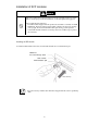
The following diagram describes the card components:
Front view
1. Communication port
From top-left: Port 13 to 16
From bottom-left: Port 1 to 12
2. Ejector
Pull the ejector forward to remove the card from
the Blade Enclosure.
3. ID LED (blue)
This LED is used to identify the switch
module/pass-through card.
4. STATUS LED (green/amber)
When this LED is lit green, it indicates the card is
working normally. When the LED is lit amber, it
indicates the card is faulty.
5. LINK/ACT LED (green)
This LED is lit green when its corresponding
communication port is connected to a network.
ID
1
1-4 5-8
9-12
13-16
2 3 4 5 6 7 8 9 10 11 12 13 14 15 16
3
4
1
2
5
通信ポー
ト
STATUSラ
ンプ
IDラン
プ