N8406-022A 1Gb Intelligent L2 Switch Smart Panel Reference Guide Part number: 856-126757-406-00 First edition: July 2008 456-01768-000 PN# 456-01768-000
Legal notices © 2008 NEC Corporation The information contained herein is subject to change without notice. The only warranties for NEC products and services are set forth in the express warranty statements accompanying such products and services. Nothing herein should be construed as constituting an additional warranty. NEC shall not be liable for technical or editorial errors or omissions contained herein. Microsoft®, Windows®, and Windows NT® are U.S. registered trademarks of Microsoft Corporation.
Contents SmartPanel Introduction ............................................................................................................................................................. 5 Additional references .............................................................................................................................................. 5 Typographical conventions ..............................................................................................................................
Show last 100 syslog messages ..................................................................................................................... 39 System user information ................................................................................................................................. 39 Layer 2 information ......................................................................................................................................... 40 FDB information menu ......................
SmartPanel Introduction The 1Gb Intelligent L2 Switch provides two switch modes: The conventional L2 switch mode, and SmartPanel mode. The switch can store up to two different software image, called image1 and image2. Normally, the conventional L2 switch software image is stored in image1, and the SmartPanel software is stored in image2. You can select which software image (image1 or image2) you want to run in switch memory. By default, the switch software is loaded from image1.
Management Network The 1Gb Intelligent L2 Switch is a Switch Module within the Blade Enclosure. The Blade Enclosure includes an Enclosure Manager Card which manages the modules and CPU Blades in the enclosure. The 1Gb Intelligent L2 Switch communicates with the Enclosure Manager Card through its internal management port (port 19). The factory default settings permit management and control access to the switch through the 10/100 Mbps Ethernet port on the Blade Enclosure, or the built-in console port.
Setting an IP address To access the switch via a Telnet, an SSH connection, or an HTTP connection, you need to have an Internet Protocol (IP) address set for the switch. You can assign the IP address only to the management interface (interface 256), associated with port 19. The management interface requests its IP address from a Dynamic Host Control Protocol (DHCP) server on the Enclosure Manager Card.
Table 3 User access levels User account Description and tasks performed user The user has no direct responsibility for switch management. He or she can view all switch status information and statistics, but cannot make any configuration changes to the switch. The user account is enabled by default, and the default password is user. The operator manages all functions of the switch. The operator can reset ports or the entire switch. By default, the operator account is disabled and has no password.
Browser-based interface Introduction This chapter explains how to access the switch browser-based interface (BBI) for the SmartPanel and configure the switch. Requirements To use the browser-based interface, you need the following: PC or workstation with network access to the switch Frame-capable Web-browser software, such as the following: Netscape Navigator 4.7x or higher Internet Explorer 6.
If the switch IP interface address has a name on your local domain name server, you can enter the name instead. Using Internet Explorer, you can enter the following: 3. Log in to the switch. If your switch and browser are properly configured, you will be asked to enter a password. Enter the account name and password for the switch. 4. Allow the BBI Dashboard page to load.
Port Status Area Menu Area Configuration Area There are three main regions on the screen. The Port Status Area is used to view port status. Click a port icon to view details. The Menu Area is used to select particular items or features to act upon. The Configuration Area is used to configure selected items. Port Status Area The Status Area contains port icons that display status information about each port. Click a port icon to display detailed information about the port.
Menu Area The Menu Area is used for selecting a particular feature to act upon. Configuration forms for the selected item appear in the Configuration Window. The Menu Area contains a tree of feature folders and names. Displays I/O bay number Click to expand or contact Click to select Click on System Settings to open it and reveal its contents. Click it again to close it. Click on any feature to load the configuration form in the Configuration Area.
Port Group Mapping SmartPanel ports can be combined into Port Groups. Up to five Port Groups are available in the SmartPanel. A Spare Ports Group is available for unused ports. VLANs and Link Aggregation Groups (trunks) are configured automatically for each Port Group. No network loops are allowed in the configuration. All external ports in the Port Group form a trunk group (static trunk or Link Aggregation Group). Port Group Characteristics SmartPanel Port Groups must have the following characteristics.
In this example, Port 1-4, 20-21 are assigned to Group1, and Port 5-8, 22-23 are assigned to Group2. The others are assigned to Spare Ports Group. Internal Port Settings On the BBI, choose Internal Port Settings to enable or disable the server blade port.
External Port Settings On the BBI, choose External Port Settings to configure the external port. The following table describes the external port configuration. Table 7 External Port Settings Command Description Port Name Sets a name for the port. The assigned port name appears next to the port number on some information and statistics screens. Enables or disables the port. Sets the link speed.
VLAN Virtual LANs (VLANs) are commonly used to split up groups of network users into manageable broadcast domains, to create logical segmentation of workgroups, and to enforce security policies among logical segments. This switch supports up to 1,000 VLANs per switch. Even though the maximum number of VLANs supported at any given time is 1,000, each can be identified with any number between 1 and 4095. VLAN 4095 is used by the management network, which includes the management port 19.
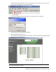
Non-Default Virtual LANs On the BBI, choose Non-Default Virtual LANs to create VLANs and assign them to Port Groups. The non-default VLAN ID is placed in the frame header of a packet in forwatding from the port. The following describes the steps to add VLAN ID. 1. Click Add VLAN to configure a new VLAN. 2. Enter a VLAN number and click OK. The following is displayed.
3. Select the corresponding radio button to assign the VLAN to a Port Group. 4. Click Apply to make the changes active. Management On the BBI, choose System Settings > Management to configure SNMP System Settings and System Log Server Settings. The following table describes the management configuration.
Table 8 Management Command Description Facility of Secondary Server This option sets the facility level of the secondary syslog server displayed. The default is 0. Local User Administration On the BBI, choose System Settings > Local User Administration to configure the user. The following table describes the user configuration. Table 9 Local User Administration Command Description Username Password User Type Enabled Eject user Defines the user name of maximum eight characters.
Remote User Administration On the BBI, choose System Settings > Remote User Administration to configure the RADIUS server or the TACACS+ server. The following table describes the configuration.
Time Services On the BBI, choose System Settings > Time Services to configure the NTP server. The following table describes the configuration. Table 11 Time Services Command General Settings Current Date Current Time Timezone Location Daylight Savings NTP Settings Time Services Update Internal (min) Primary Server Secondary Server Description Configures the system date. Configures the system time using a 24-hour clock format. Configures the time zone where the switch resides.
Trunking Trunk groups provide super-bandwidth, multi-link connections between SmartPanel or other trunk-capable devices. A trunk group is a group of ports that act together, combining their bandwidth to create a single, larger virtual link. SmartPanel trunk groups are static link aggregation groups that are compatible with Cisco’s EtherChannel technology. The SmartPanel is statically configured to place each Port Group into a separate trunk group.
Trunk Group configuration On the BBI, choose System Settings > Uplink/Group to enable or disable the Link Aggregation Control Protocol. When enabled, the external ports are configured as a LACP trunk group. When disabled, they are configured as a static trunk group. The default is disabled. Failover The primary application for Failover is to support Network Adapter Teaming. With Network Adapter Teaming, the NICs on each server all share the same IP address, and are configured into a team.
Failover configuration On the BBI, choose System Settings > Uplink/Group to configure the Switch Failover and Number of Links to Trigger Failover. IGMP Snooping IGMP Snooping allows the SmartPanel to forward multicast traffic only to those ports that request it. IGMP Snooping prevents multicast traffic from being flooded to all ports. The SmartPanel learns which server hosts are interested in receiving multicast traffic, and forwards it only to ports connected to those servers.
Boot Management On the BBI, choose System Settings > Boot Management to backup or restore the switch configuration, update the switch software image, or get dump file. The following table describes the configuration. Table 12 Boot Management Command Description Reboot the Module button Next boot config block Reboots the switch. Selects the Configuration Block file (active, backup or factory) that will run after the next reboot.
Table 12 Boot Management Command Description Put TS Dump Uploads the TS (tech support) dump file to the TFTP or FTP server specified in Remote File Name. Uploads the core (PANIC) dump file to the TFTP or FTP server specified in Remote Filename. Deletes the core dump in flash memory. Put Crash Dump Clear Crash Dump IMPORTANT: When the switch software is changed (NormalPanel or SmartPanel) and the switch is rebooted, the switch configuration is removed and the switch runs factory configuration block.
Command Line Interface Introduction The CLI is used for viewing switch information and statistics. In addition, the administrator can use the CLI for performing all levels of switch configuration. To make the CLI easy to use, the various commands have been logically grouped into a series of menus and submenus. Each menu displays a list of commands and/or submenus that are available, along with a summary of what each command will do.
Global commands Some basic commands are recognized throughout the menu hierarchy. These commands are useful for obtaining online Help, navigating through menus, and for applying and saving configuration changes. For help on a specific command, type help. The following screen displays: Global Commands: [can be issued from any menu] help up print lines verbose exit diff apply save ping traceroute telnet pushd popd who pwd quit revert history The following are used to navigate the menu structure: .
Table 13 Global commands Command Action popd who Returns to the last pushd location. Displays users who are logged in. Command line history and editing Using the command line interface, you can retrieve and modify previously entered commands with just a few keystrokes. The following options are available globally at the command line: Table 14 Command line history and editing options Option Description history !! !n or Displays a numbered list of the last ten previously entered commands.
Command line interface shortcuts The following shortcuts allow you to enter commands quickly and easily. Command stacking As a shortcut, you can type multiple commands on a single line, separated by forward slashes (/). You can connect as many commands as required to access the menu option that you want.
Information Menu Introduction You can view configuration information for the switch in the user, operator, and administrator command modes. This chapter discusses how to use the CLI to display switch information.
System Information Menu Command: /info/sys [System Menu] snmpv3 general log user dump - SNMPv3 Information Menu Show general system information Show last 100 syslog messages Show current user status Dump all system information The following table describes the System Information Menu options. Table 16 System Information Menu options Command Usage snmpv3 general Displays the SNMP v3 Menu.
Table 17 SNMPv3 Information Menu options Command Usage tparam notify dump Displays the Target parameters table. Displays the Notify table. Displays all the SNMPv3 information.
SNMPv3 Access Table information Command: /info/sys/snmpv3/access Group Name ---------v1v2grp admingrp Model ------snmpv1 usm Level -----------noAuthNoPriv authPriv ReadV WriteV --------- -------iso iso iso iso NotifyV ------v1v2only iso The access control sub system provides authorization services. The vacmAccessTable maps a group name, security information, a context, and a message type, which could be the read or write type of operation or notification into a MIB view.
Field Description Index Name User Name Tag Displays the unique index value of a row in this table. Displays the community string, which represents the configuration. Displays the User Security Model (USM) user name. Displays the community tag. This tag specifies a set of transport endpoints from which a command responder application accepts management requests and to which a command responder application sends an SNMP trap.
SNMPv3 Notify Table information Command: /info/sys/snmpv3/notify Name Tag -------------------- -------------------v1v2trap v1v2trap The following table describes the SNMPv3 Notify Table information. Table 25 SNMPv3 Notify Table Field Description Name Tag The locally arbitrary, but unique identifier associated with this snmpNotifyEntry. This represents a single tag value which is used to select entries in the snmpTargetAddrTable.
Engine ID = 80:00:07:50:03:00:0F:6A:F8:EF:00 usmUser Table: User Name Protocol -------------------------------- -------------------------------admin NO AUTH, NO PRIVACY adminmd5 HMAC_MD5, DES PRIVACY adminsha HMAC_SHA, DES PRIVACY v1v2only NO AUTH, NO PRIVACY vacmAccess Group Name ---------admin v1v2grp admingrp Table: Model ------usm snmpv1 usm Level -----------noAuthNoPriv noAuthNoPriv authPriv ReadV ------org org org WriteV -------org org org vacmViewTreeFamily Table: View Name Subtree Mask --------
System information Command: /info/sys/gen System Information at Time zone: Asia/Tokyo 6:56:22 Thu Jan 11, 2006 Blade Network Technologies 1Gb Intelligent L2 Switch, SmartPanel sysName: sysLocation: RackId: NEC01A 6X00125 RackName: Default_Rack_Name EnclosureSerialNumber: NEC01A 6X00125 EnclosureName: Default_Chassis_Name BayNumber: 1 Switch is up 0 days, 14 hours, 56 minutes and 22 seconds. Last boot: power cycle MAC address: 00:17:ef:80:7a:00 IP (If 256) address: 10.14.4.
Show last 100 syslog messages Command: /info/sys/log Date ---Jul 8 Jul 8 Jul 8 Jul 8 Jul 8 Jul 8 Jul 8 Jul 8 Jul 8 Jul 8 Jul 8 Jul 8 Jul 8 Jul 8 Jul 8 Jul 8 Jul 8 Jul 8 Jul 8 Jul 8 Time ---17:25:41 17:25:41 17:25:41 17:25:41 17:25:41 17:25:41 17:25:41 17:25:41 17:25:41 17:25:41 17:25:41 17:25:41 17:25:41 17:25:41 17:25:42 17:25:42 17:25:42 17:25:42 17:25:42 17:25:42 Severity level ----------------NOTICE NOTICE NOTICE NOTICE NOTICE NOTICE NOTICE NOTICE NOTICE NOTICE NOTICE NOTICE NOTICE NOTICE NOTICE NOTIC
Layer 2 information Command: /info/l2 [Layer 2 Menu] fdb - Forwarding Database Information Menu trunk - Show Trunk Group information dump - Dump all layer 2 information The following table describes the Layer 2 Information menu options. Table 27 Layer 2 information menu options Command Usage fdb trunk dump Displays the Forwarding Database Information Menu. When trunk groups are configured, you can view the state of each port in the various trunk groups.
FDB information menu Command: /info/l2/fdb [Forwarding Database Menu] find - Show a single FDB entry by MAC address port - Show FDB entries on a single port vlan - Show FDB entries on a single VLAN state - Show FDB entries by state dump - Show all FDB entries The forwarding database (FDB) contains information that maps the media access control (MAC) address of each known device to the switch port where the device address was learned.
Trunk group information Command: /info/l2/trunk Trunk group 1, Enabled Protocol - Static port state: 20: forwarding 21: forwarding 22: forwarding 23: forwarding 24: forwarding When trunk groups are configured, you can view the state of each port in the various trunk groups.
ARP information Command: /info/arp [Address Resolution Protocol Menu] find - Show a single ARP entry by IP address port - Show ARP entries on a single port vlan - Show ARP entries on a single VLAN addr - Show ARP entries for switch's interface dump - Show all ARP entries The Address Resolution Protocol (ARP) information includes IP address and MAC address of each entry, address status flags, VLAN, and port for the address, and port referencing information.
IP information Command: /info/l3/ip Interface information: 1: 47.80.23.243 255.255.254.0 47.80.23.255, Default gateway information: metric strict 4: 47.80.23.
Link status information Command: /info/link -----------------------------------------------------------------Port Speed Duplex Flow Ctrl Link --------------- --TX-----RX------1 1000 full yes yes up 2 1000 full yes yes up 3 1000 full yes yes up 4 1000 full yes yes up 5 any any yes yes down 6 any any yes yes down 7 any any yes yes down 8 any any yes yes up 9 any any yes yes down 10 any any yes yes down 11 any any yes yes down 12 any any yes yes down 13 any any yes yes down 14 any any yes yes down 15 any any y
Port number Port name VLAN membership N8406-022A 1Gb Intelligent L2 Switch Smart Panel Reference Guide 46
Group information Command: /info/group Group 1: Internal Ports: 1-16 External Ports: 20-24 Port VLAN ID: 1 Number of nondefault vlans in group: 0 VLANs: empty Default Group Vlan: 1 Trunk group 13: Enabled port state: 20: forwarding 21: forwarding 22: forwarding 23: forwarding 24: forwarding LACP Enabled IGMP Disabled Failover Enabled Failover Limit = 0 This displays the information of Port Group 1-5 and Spare Ports Group.
Statistics Menu Introduction You can view switch performance statistics in the user, operator, and administrator command modes. This chapter discusses how to use the CLI to display switch statistics. Menu information Command: /stats [Statistics Menu] port - Port Stats Menu clrports – Clear stats for all ports l2 - Layer 2 Stats Menu l3 - Layer 3 Stats Menu mp - MP-specific Stats Menu ntp - Show NTP stats dump - Dump all stats The following table describes the Statistics Menu options.
Port Statistics Menu Command: /stats/port [Port Statistics Menu] brg - Show bridging ("dot1") stats ether - Show Ethernet ("dot3") stats if - Show interface ("if") stats ip - Show Internet Protocol ("IP") stats link - Show link stats clear - Clear all port stats This menu displays traffic statistics on a port-by-port basis.
Ethernet statistics Command: /stats/port /ether Ethernet statistics for port 1: dot3StatsAlignmentErrors: dot3StatsFCSErrors: dot3StatsSingleCollisionFrames: dot3StatsMultipleCollisionFrames: dot3StatsLateCollisions: dot3StatsExcessiveCollisions: dot3StatsInternalMacTransmitErrors: dot3StatsFrameTooLongs: dot3StatsInternalMacReceiveErrors: 0 0 0 0 0 0 0 0 0 The following table describes the Ethernet statistics for a selected port: Table 37 Ethernet statistics for port Statistics Description
Table 37 Ethernet statistics for port Statistics Description dot3StatsInternalMacTransmitErrors A count of frames for which transmission on a particular interface fails due to an internal MAC sublayer transmit error. A frame is only counted by an instance of this object if it is not counted by the corresponding instance of either the dot3StatsLateCollisions object, the dot3StatsExcessiveCollisions object, or the dot3StatsCarrierSenseErrors object.
Table 38 Interface statistics for port Statistics Description Errors—IfHCIn For packet-oriented interfaces, the number of inbound packets that contained errors preventing them from being delivered to a higher-layer protocol. For character-oriented or fixed-length interfaces, the number of inbound transmission units that contained errors preventing them from being deliverable to a higher-layer protocol. The total number of octets transmitted out of the interface, including framing characters.
Link statistics Command: /stats/port /link Link statistics for port 1: linkStateChange: 2 The following table describes the link statistics for a selected port: Table 40 Link statistics for port Statistic Description linkStateChange The total number of link state changes. Layer 2 statistics Menu Command: /stats/l2 [Layer 2 Statistics Menu] fdb - Show FDB stats lacp - Show LACP stats The following table describes the Layer 2 statistics menu options.
Layer 3 statistics Menu Command: /stats/l3 [Layer 3 Statistics Menu] ip - Show IP stats route - Show route stats arp - Show ARP stats icmp - Show ICMP stats tcp - Show TCP stats udp - Show UDP stats igmp - Show IGMP stats clrigmp - Clear IGMP stats ipclear - Clear IP stats dump - Dump layer 3 stats The following table describes the Layer 3 statistics menu options. Layer 3 functionality is limited in this release.
Table 44 IP statistics Statistics Description ipInDiscards The number of input IP datagrams for which no problems were encountered to prevent their continued processing, but which were discarded (for example, for lack of buffer space). This counter does not include any datagrams discarded while awaiting re-assembly. The total number of input datagrams successfully delivered to IP user-protocols (including ICMP).
ICMP statistics Command: /stats/l3/icmp ICMP statistics: icmpInMsgs: icmpInDestUnreachs: icmpInParmProbs: icmpInRedirects: icmpInEchoReps: icmpInTimestampReps: icmpInAddrMaskReps: icmpOutErrors: icmpOutTimeExcds: icmpOutSrcQuenchs: icmpOutEchos: icmpOutTimestamps: icmpOutAddrMasks: 245802 41 0 0 244350 0 0 0 0 0 253777 0 0 icmpInErrors: icmpInTimeExcds: icmpInSrcQuenchs: icmpInEchos: icmpInTimestamps: icmpInAddrMasks: icmpOutMsgs: icmpOutDestUnreachs: icmpOutParmProbs: icmpOutRedirects: icmpOutEchoReps: i
TCP statistics Command: /stats/l3/tcp TCP statistics: tcpRtoAlgorithm: tcpRtoMax: tcpActiveOpens: tcpAttemptFails: tcpInSegs: tcpRetransSegs: tcpCurBuff: tcpOutRsts: 4 240000 252214 528 756401 0 0 417 tcpRtoMin: tcpMaxConn: tcpPassiveOpens: tcpEstabResets: tcpOutSegs: tcpInErrs: tcpCurConn: 0 512 7 4 756655 0 3 The following table describes the Transmission Control Protocol (TCP) statistics: Table 48 TCP statistics Statistics Description tcpRtoAlgorithm The algorithm used to determine the timeout val
UDP statistics Command: /stats/l3/udp UDP statistics: udpInDatagrams: udpInErrors: 54 0 udpOutDatagrams: udpNoPorts: 43 1578077 The following table describes the User Datagram Protocol (UDP) statistics: Table 49 UDP statistics Statistics Description udpInDatagrams udpOutDatagrams udpInErrors The total number of UDP datagrams delivered to the switch. The total number of UDP datagrams sent from this switch.
Management Processor statistics Command: /stats/mp [MP-specific Statistics Menu] i2c - Show i2c stats pkt - Show Packet stats tcb - Show All TCP control blocks in use ucb - Show All UDP control blocks in use cpu - Show CPU utilization The following table describes the MP-specific Statistics Menu options: Table 51 MP-specific Statistics Menu Command Usage i2c pkt tcb ucb cpu Displays i2c statistics. Displays packet statistics, to check for leads and load.
TCP statistics Command: /stats/mp/tcb All TCP allocated control blocks: 10ad41e8: 0.0.0.0 0 <=> 0.0.0.0 10ad5790: 47.81.27.5 1171 <=> 47.80.23.243 80 23 listen established The following table describes the Transmission Control Protocol (TCP) control block (TCB) statistics shown in this example: Table 53 MP specified TCP statistics Description Example statistic Memory 10ad41e8/10ad5790 Destination IP address Destination port Source IP Source port State 0.0.0.0/47.81.27.5 0/1171 0.0.0.0/47.80.23.
NTP statistics Command: /stats/ntp NTP statistics: Primary Server: Requests Sent: Responses Received: Updates: Secondary Server: Requests Sent: Responses Received: Updates: 17 17 1 0 0 0 Last update based on response from primary server. Last update time: 18:04:16 Tue Mar 13, 2006 Current system time: 18:55:49 Tue Mar 13, 2006 The switch uses NTP (Network Timing Protocol) version 3 to synchronize the switch’s internal clock with an atomic time-calibrated NTP server.
Configuration Menu Introduction The Configuration Menu is only available from an administrator login. It includes submenus for configuring every aspect of the switch. Changes to configuration are not active until explicitly applied. Changes can be saved to nonvolatile memory (NVRAM).
Viewing pending changes You can view all pending configuration changes by entering diff at any CLI prompt: # diff You can view all pending configuration changes that have been applied but not saved to flash memory by entering diff flash at any CLI prompt: # diff flash Applying pending changes To make your configuration changes active, you must apply them. To apply configuration changes, enter the following command at any prompt: # apply NOTE: All configuration changes take effect immediately when applied.
System configuration Command: /cfg/sys [System Menu] syslog sshd radius tacacs+ ntp ssnmp access watchdog date time timezone olddst dlight idle notice bannr hprompt dhcp rstctrl cur - Syslog Menu SSH Server Menu RADIUS Authentication Menu TACACS+ Authentication Menu NTP Server Menu System SNMP Menu System Access Menu Watchdog Menu Set system date Set system time Set system timezone (daylight savings) Set system DST for US Set system daylight savings Set timeout for idle CLI sessions Set login notice Set l
Table 58 System Configuration Menu options Command Usage rstctrl Enables or disables reset when the panic occurs on the switch software. The default value is enabled. Displays the current system parameters.
Secure Shell Server configuration Command: /cfg/sys/sshd [SSHD Menu] interval– scpadm – hkeygen skeygen sshport ena dis on off cur - Set Interval for generating the RSA server key Set SCP-only admin password Generate the RSA host key Generate the RSA server key Set SSH server port number Enable the SCP apply and save Disable the SCP apply and save Turn SSH server ON Turn SSH server OFF Display current SSH server configuration Telnet traffic on the network is not secure.
RADIUS server configuration Command: /cfg/sys/radius [RADIUS Server prisrv secsrv secret secret2 port retries timeout bckdoor secbd on off cur - Menu] Set primary RADIUS server address Set secondary RADIUS server address Set primary RADIUS server secret Set secondary RADIUS server secret Set RADIUS port Set RADIUS server retries Set RADIUS server timeout Enable/disable RADIUS backdoor for telnet/ssh/http/https Enable/disable RADIUS secure backdoor for telnet/ssh/http/https Turn RADIUS authentication ON Tur
TACACS+ server configuration Command: /cfg/sys/tacacs+ [TACACS+ Server Menu] prisrv - Set IP address of primary TACACS+ server secsrv - Set IP address of secondary TACACS+ server secret - Set secret for primary TACACS+ server secret2 - Set secret for secondary TACACS+ server port - Set TACACS+ port number retries - Set number of TACACS+ server retries timeout - Set timeout value of TACACS+ server retries bckdoor - Enable/disable TACACS+ backdoor for telnet/ssh/http/https secbd - Enable/disable TACACS+ secur
IMPORTANT: If TACACS+ is enabled, you must login using TACACS+ authentication when connecting via the console or Telnet/SSH/HTTP/HTTPS. Backdoor for console is always enabled, so you can connect using notacacs and the administrator password even if the backdoor (bckdoor) or secure backdoor (secbd) are disabled. If backdoor is enabled (bckdoor ena), type in notacacs as a backdoor to bypass TACACS+ checking, and use the administrator password to log into the switch.
System SNMP configuration Command: /cfg/sys/ssnmp [SNMP Menu] snmpv3 name locn cont rcomm wcomm timeout reqport cur - SNMPv3 Menu Set SNMP "sysName" Set SNMP "sysLocation" Set SNMP "sysContact" Set SNMP read community string Set SNMP write community string Set timeout for the SNMP state machine Set SNMP request port number Display current SNMP configuration The switch software supports SNMP-based network management.
SNMPv3 configuration Command: /cfg/sys/ssnmp/snmpv3 [SNMPv3 Menu] usm view access group comm taddr tparam notify v1v2 cur - usmUser Table Menu vacmViewTreeFamily Table Menu vacmAccess Table Menu vacmSecurityToGroup Table Menu community Table Menu targetAddr Table Menu targetParams Table Menu notify Table Menu Enable/disable V1/V2 access Display current SNMPv3 configuration SNMP version 3 (SNMPv3) is an extensible SNMP Framework that supplements the SNMPv2 Framework by supporting the following: a new SNMP
SNMPv3 User Security Model configuration Command: /cfg/sys/ssnmp/snmpv3/usm [SNMPv3 usmUser name auth authpw priv privpw del cur - 1 Menu] Set USM user name Set authentication protocol Set authentication password Set privacy protocol Set privacy password Delete usmUser entry Display current usmUser configuration You can make use of a defined set of user identities using this Security Model. An SNMP engine must have the knowledge of applicable attributes of a user.
Table 67 SNMPv3 View Configuration Menu options Command Description type included|excluded Selects whether the corresponding instances of vacmViewTreeFamilySubtree and vacmViewTreeFamilyMask define a family of view subtrees, which is included in or excluded from the MIB view. Deletes the vacmViewTreeFamily group entry. Displays the current vacmViewTreeFamily configuration.
SNMPv3 Group configuration Command: /cfg/sys/ssnmp/snmpv3/group [SNMPv3 vacmSecurityToGroup 1 Menu] model - Set security model uname - Set USM user name gname - Set group name del - Delete vacmSecurityToGroup entry cur - Display current vacmSecurityToGroup configuration The following table describes the SNMPv3 Group Configuration Menu options.
SNMPv3 Target Address Table configuration Command: /cfg/sys/ssnmp/snmpv3/taddr [SNMPv3 snmpTargetAddrTable 1 Menu] name - Set target address name addr - Set target transport address IP port - Set target transport address port taglist - Set tag list pname - Set targetParams name del - Delete targetAddrTable entry cur - Display current targetAddrTable configuration This menu allows you to configure an entry of a transport address that transmits SNMP traps.
The following table describes the SNMPv3 Target Parameters Table Configuration Menu options. Table 72 SNMPv3 Target Parameters Table Configuration Menu options Command Description name <1-32 characters> mpmodel snmpv1|snmpv2c|snm pv3 model usm|snmpv1|snmpv2 uname <1-32 characters> level noAuthNoPriv|authN oPriv|authPriv Configures the locally arbitrary, but unique identifier that is associated with this entry. del cur Configures the message processing model that is used to generate SNMP messages.
System Access configuration Command: /cfg/sys/access [System Access Menu] mgmt - Management Network Definition Menu user - User Access Control Menu (passwords) http - Enable/disable HTTP (Web) access https - HTTPS Web Access Menu wport - Set HTTP (Web) server port number snmp - Set SNMP access control tnet - Enable/disable Telnet access tnport - Set Telnet server port number cur - Display current system access configuration The following table describes the System Access Configuration menu options.
User Access Control configuration Command: /cfg/sys/access/user [User Access Control Menu] uid - User ID Menu eject - Eject user usrpw - Set user password (user) opw - Set operator password (oper) admpw - Set administrator password (admin) cur - Display current user status The following table describes the User Access Control menu options.
HTTPS Access configuration Command: /cfg/sys/access/https [https Menu] access port generate certSave cur - Enable/Disable HTTPS Web access HTTPS WebServer port number Generate self-signed HTTPS server certificate save HTTPS certificate Display current SSL Web Access configuration The following table describes the HTTPS Access Configuration menu options. Table 78 HTTPS Access Configuration menu options Command Description access enable|disable Enables or disables BBI access (Web access) using HTTPS.
Port configuration Command: /cfg/port [Port 1 Menu] speed fctl auto name ena dis cur - Set link speed and force full duplex mode Set flow control Set auto negotiation Set port name Enable port Disable port Display current port configuration This menu enables you to configure settings for individual switch ports. This command is enabled by default. NOTE: Port 19 is a port for switch management interface (interface 256). Cross-link ports (17-18) are not available on the SmartPanel software.
Group configuration Command: /cfg/group <1-5> [Group 1 Menu] addport remport addvlan remvlan pvid igmp failover limit lacp cur - Add ports to the group Remove ports from the group Add non-default (tagged) VLANs to the group Remove non-default (tagged) VLANs from the group Set default port VLAN id for the group Enable/Disable IGMP Snooping for the group Enable/Disable Failover for the group Number of External Links to trigger failover Enable/Disable LACP for the group Display current group configuration Us
Configuration Dump Command: /cfg/dump The dump program writes the current switch configuration to the terminal screen. To start the dump program, at the Configuration# prompt, enter: Configuration# dump The configuration is displayed with parameters that have been changed from the default values. The screen display can be captured, edited, and placed in a script file, which can be used to configure other switches.
Operations Menu Introduction Operations-level commands are used for making immediate and temporary changes to switch configuration. The Operations Menu is used for bringing ports temporarily in and out of service. This menu is available only from an administrator and operator login.
Boot Options Menu Introduction You must be logged in to the switch as the administrator to use the Boot Options Menu. The Boot Options Menu provides options for: Selecting a switch software image to be used when the switch is next reset. Selecting a configuration block to be used when the switch is next reset. Downloading or uploading a new software image to the switch via FTP or TFTP.
The exact form of the name will vary by FTP/TFTP server. However, the file location is normally relative to the FTP/TFTP directory. 5. Enter the username, if you are using a FTP server: Enter username for FTP server or hit return for TFTP server: 6. Enter the password for the FTP server (if prompted): Enter password for username on FTP server: 7. The system prompts you to confirm your request.
Uploading a software image from the switch You can upload a software image from the switch to a FTP or TFTP server. 1. At the Boot Options# prompt, enter: Boot Options# ptimg 2. The system prompts you for information. Enter the desired image: Enter name of switch software image to be uploaded ["image1"|"image2"|"boot"]: 3. Enter the name or the IP address of the FTP or TFTP server: Enter hostname or IP address of FTP/TFTP server: 4.
Resetting the switch You can reset the switch to make your software image file and configuration block changes occur. Resetting the switch causes the Spanning Tree Protocol to restart. This process can be lengthy, depending on the topology of your network. To reset the switch, at the Boot Options# prompt, enter: >> Boot Options# reset You are prompted to confirm your request. Current switch software information To display the current switch software information, enter the following.
Maintenance Menu Introduction The Maintenance Menu is used for debugging purposes, enabling you to generate a technical support dump of the critical state information in the switch, and to clear entries in the Forwarding Database and the Address Resolution Protocol (ARP). This menu is available only from an administrator and operator login.
Forwarding Manipulation options Command: /maint/fdb [FDB Manipulation Menu] find - Show a single FDB entry by MAC address port - Show FDB entries for a single port vlan - Show FDB entries for a single VLAN dump - Show all FDB entries add - Add a FDB entry del - Delete a FDB entry clear - Clear entire FDB, then re-add static entries The Forwarding Database (FDB) Manipulation Menu can be used to view information and to delete a MAC address from the Forwarding Database or clear the entire Forwarding Database.
ARP cache options Command: /maint/arp [Address Resolution Protocol Menu] find - Show a single ARP entry by IP address port - Show ARP entries on a single port vlan - Show ARP entries on a single VLAN addr - Show ARP entries for switch's interfaces dump - Show all ARP entries clear - Clear ARP cache The following table describes the Address Resolution Protocol Menu options: Table 89 Address Resolution Protocol Menu options Command Usage find Shows a single ARP entry by IP address.
IGMP Multicast Routers options Command: /maint/igmp/mrouter [IGMP Multicast vlan dump clear - Routers Menu] Show all multicast router ports on a single vlan Show all multicast router ports Clear multicast router port table The following table describes the IGMP Multicast Routers Maintenance Menu options. Table 92 IGMP Multicast Group Menu options Command Usage vlan <1-4094> dump clear Shows IGMP Multicast groups on a single VLAN. Shows all IGMP Multicast routers.
FTP/TFTP system dump put Command: /maint/ptdmp Use this command to put (save) the system dump to a FTP or TFTP server. NOTE: If the FTP or TFTP server is running SunOS or the Solaris operating system, the specified ptdmp file must exist prior to executing the ptdmp command, and must be writable (set with proper permission, and not locked by any application). The contents of the specified file will be replaced with the current dump data.