N8406-022A 1Gb Intelligent L2 Switch Command Reference Guide (AOS) Part number: 856-126757-206-00 First edition: July 2008 456-01765-000 PN# 456-01765-000
Legal notices © 2008 NEC Corporation The information contained herein is subject to change without notice. The only warranties for NEC products and services are set forth in the express warranty statements accompanying such products and services. Nothing herein should be construed as constituting an additional warranty. NEC shall not be liable for technical or editorial errors or omissions contained herein. Microsoft®, Windows®, and Windows NT® are U.S. registered trademarks of Microsoft Corporation.
Contents Command line interface Introduction ............................................................................................................................................................. 7 Additional references .............................................................................................................................................. 7 Connecting to the switch ...................................................................................................................
ARP address list information ........................................................................................................................... 39 Show all ARP entry information ...................................................................................................................... 39 IP information .......................................................................................................................................................
SNMPv3 View configuration............................................................................................................................ 77 SNMPv3 View-based Access Control Model configuration............................................................................. 78 SNMPv3 Group configuration ......................................................................................................................... 79 SNMPv3 Community Table configuration .....................................
Selecting a software image to run ...................................................................................................................... 114 Uploading a software image from the switch ...................................................................................................... 114 Selecting a configuration block ........................................................................................................................... 115 Resetting the switch ........................
Command line interface Introduction The 1Gb Intelligent L2 Switch is ready to perform basic switching functions right out of the box. Some of the more advanced features, however, require some administrative configuration before they can be used effectively.
To establish a console connection with the switch: 1. Connect the terminal to the console port using the null modem cable. 2. Power on the terminal. 3. Press the Enter key a few times on the terminal to establish the connection. 4. You will be required to enter a password for access to the switch. (For more information, see the ―Setting passwords‖ section in the ―First-time configuration‖ chapter.
The supported SSH encryption and authentication methods are listed below. Server Host Authentication—Client RSA authenticates the switch in the beginning of every connection Key Exchange—RSA Encryption: AES256-CBC AES192-CBC AES128-CBC 3DES-CBC 3DES ARCFOUR User Authentication—Local password authentication; Remote Authentication Dial-in User Service (RADIUS) The following SSH clients are supported: SSH 3.0.1 for Linux (freeware) SecureCRT® 4.1.8 (VanDyke Technologies, Inc.) OpenSSH_3.
Table 2 User access levels User account Description and tasks performed User The user has no direct responsibility for switch management. He or she can view all switch status information and statistics, but cannot make any configuration changes to the switch. The user account is enabled by default, and the default password is user. The operator manages all functions of the switch. The operator can reset ports or the entire switch. By default, the operator account is disabled and has no password.
Menu basics Introduction The AOS CLI is used for viewing switch information and statistics. In addition, the administrator can use the CLI for performing all levels of switch configuration. To make the CLI easy to use, the various commands have been logically grouped into a series of menus and submenus. Each menu displays a list of commands and/or submenus that are available, along with a summary of what each command will do.
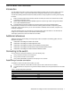
Global commands Some basic commands are recognized throughout the menu hierarchy. These commands are useful for obtaining online Help, navigating through menus, and for applying and saving configuration changes. For help on a specific command, type help. The following screen displays: Global Commands: [can be issued from any menu] help up print lines verbose exit diff apply save ping traceroute telnet pushd popd who pwd quit revert history The following are used to navigate the menu structure: .
Table 4 Global commands Command Action pushd popd who Remembers the current location in the directory of menu commands. Returns to the last pushd location. Displays users who are logged in. Command line history and editing Using the command line interface, you can retrieve and modify previously entered commands with just a few keystrokes.
Command line interface shortcuts The following shortcuts allow you to enter commands quickly and easily. Command stacking As a shortcut, you can type multiple commands on a single line, separated by forward slashes (/). You can connect as many commands as required to access the menu option that you want.
First-time configuration Introduction This chapter describes how to perform first-time configuration and how to change system passwords. To begin first-time configuration of the switch, perform the following steps. 1. Connect to the switch console. After connecting, the login prompt displays. Blade Network Technologies 1Gb Intelligent L2 Switch. Enter password: 2. Enter admin as the default administrator password. The system displays the Main Menu with administrator privileges.
4. Apply and save configuration if you are not configuring the switch with Telnet support. Otherwise apply and save after the performing the ―Optional Setup for Telnet Support‖ steps. >> System# apply >> System# save Setting passwords NEC recommends that you change all passwords after initial configuration and as regularly as required under the network security policies. See the ―Accessing the switch‖ section in the ―Command line interface‖ chapter for a description of the user access levels.
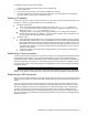
[System Menu] syslog - Syslog Menu sshd - SSH Server Menu radius - RADIUS Authentication Menu tacacs+ - TACACS+ Authentication Menu ntp - NTP Server Menu ssnmp - System SNMP Menu access - System Access Menu date - Set system date time - Set system time timezone - Set system timezone (daylight savings) olddst - Set system DST for US idle - Set timeout for idle CLI sessions notice - Set login notice bannr - Set login banner hprompt - Enable/disable display hostname (sysName) in CLI prompt bootp - Enable/disab
5. Enter the current administrator password at the prompt. Only the administrator can change the user password. Entering the administrator password confirms your authority. Changing USER password; validation required... Enter current administrator password: 6. Enter the new user password at the prompt: Enter new user password: 7. Enter the new user password, again, at the prompt: Re-enter new user password: 8.
Information Menu Introduction You can view configuration information for the switch in the user, operator, and administrator command modes. This chapter discusses how to use the CLI to display switch information.
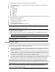
System Information Menu Command: /info/sys [System Menu] snmpv3 general log user dump - SNMPv3 Information Menu Show general system information Show last 100 syslog messages Show current user status Dump all system information The following table describes the System Information Menu options. Table 7 System Information Menu options Command Usage snmpv3 general Displays the SNMP v3 Menu.
The following table describes the SNMPv3 Information Menu options. Table 8 SNMPv3 Information Menu options Command Usage usm view access group Displays User Security Model (USM) table information. Displays information about view name, subtrees, mask and type of view. Displays View-based Access Control information. Displays information about the group that includes the security model, user name, and group name. Displays information about the community table. Displays the Target Address table.
SNMPv3 View Table information Command: /info/sys/snmpv3/view View Name Subtree ------------------ ---------------------------iso 1 v1v2only 1 v1v2only 1.3.6.1.6.3.15 v1v2only 1.3.6.1.6.3.16 v1v2only 1.3.6.1.6.3.
SNMPv3 Group Table information Command: /info/sys/snmpv3/group Sec Model ---------snmpv1 usm usm User Name ----------------------------v1v2only adminmd5 adminsha Group Name ------------------------------v1v2grp admingrp admingrp A group is a combination of security model and security name that defines the access rights assigned to all the security names belonging to that group. The group is identified by a group name. The following table describes the SNMPv3 Group Table information.
SNMPv3 Target Parameters Table information Command: /info/sys/snmpv3/tparam Name MP Model User Name Sec Model Sec Level ------------------- -------- -------------------- --------- ----------v1v2param snmpv2c v1v2only snmpv1 noAuthNoPriv The following table describes the SNMPv3 Target Parameters Table information. Table 15 SNMPv3 Target Parameters Table Field Description Name Displays the locally arbitrary, but unique identifier associated with this snmpTargeParamsEntry.
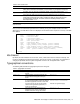
SNMPv3 dump Command: /info/sys/snmpv3/dump Engine ID = 80:00:07:50:03:00:0F:6A:F8:EF:00 usmUser Table: User Name Protocol -------------------------------- -------------------------------admin NO AUTH, NO PRIVACY adminmd5 HMAC_MD5, DES PRIVACY adminsha HMAC_SHA, DES PRIVACY v1v2only NO AUTH, NO PRIVACY vacmAccess Group Name ---------admin v1v2grp admingrp Table: Model ------usm snmpv1 usm Level -----------noAuthNoPriv noAuthNoPriv authPriv ReadV ------org org org WriteV -------org org org vacmViewTreeFa
System information Command: /info/sys/gen System Information at Time zone: Asia/Tokyo 6:56:22 Thu Jan 11, 2006 Blade Network Technologies 1Gb Intelligent L2 Switch sysName: sysLocation: RackId: NEC01A 6X00125 RackName: Default_Rack_Name EnclosureSerialNumber: NEC01A 6X00125 EnclosureName: Default_Chassis_Name BayNumber: 1 Switch is up 0 days, 14 hours, 56 minutes and 22 seconds. Last boot reason: reset from console MAC address: 00:10:00:01:00:01 IP (If 1) address: 10.14.4.
Show last 100 syslog messages Command: /info/sys/log Date ---Jul 8 Jul 8 Jul 8 Jul 8 Jul 8 Jul 8 Jul 8 Jul 8 Jul 8 Jul 8 Jul 8 Jul 8 Jul 8 Jul 8 Jul 8 Jul 8 Jul 8 Jul 8 Jul 8 Jul 8 Time ---17:25:41 17:25:41 17:25:41 17:25:41 17:25:41 17:25:41 17:25:41 17:25:41 17:25:41 17:25:41 17:25:41 17:25:41 17:25:41 17:25:41 17:25:42 17:25:42 17:25:42 17:25:42 17:25:42 17:25:42 Severity level ----------------NOTICE NOTICE NOTICE NOTICE NOTICE NOTICE NOTICE NOTICE NOTICE NOTICE NOTICE NOTICE NOTICE NOTICE NOTICE NOTIC
Layer 2 information Command: /info/l2 [Layer 2 Menu] fdb - Forwarding Database Information Menu lacp - Link Aggregation Control Protocol Menu stp - Show STP information cist - Show CIST information trunk - Show Trunk Group information vlan - Show VLAN information gen - Show general information dump - Dump all layer 2 information The following table describes the Layer 2 Information menu options.
FDB information menu Command: /info/l2/fdb [Forwarding Database Menu] find - Show a single FDB entry by MAC address port - Show FDB entries on a single port vlan - Show FDB entries on a single VLAN state - Show FDB entries by state dump - Show all FDB entries The forwarding database (FDB) contains information that maps the media access control (MAC) address of each known device to the switch port where the device address was learned.
Link Aggregation Control Protocol information Command: /info/l2/lacp [LACP Menu] aggr port dump - Show LACP aggregator information for the port - Show LACP port information - Show all LACP ports information The following table describes the Link Aggregation Control Protocol Menu options. Table 20 LACP information Command Usage aggr port dump Displays LACP aggregator information for the port. Displays LACP information for the port. Displays all LACP information parameters.
Spanning Tree information Command: /info/l2/stp -----------------------------------------------------------------upfast disabled, update 40 -----------------------------------------------------------------Spanning Tree Group 1: On (STP/PVST+) VLANs: 1 Current Root: 8000 00:02:a5:d1:0f:ed Parameters: Port ---1 2 3 Priority 32768 Priority -------0 0 0 Cost ---0 0 0 Path-Cost 8 Hello 2 MaxAge 20 FastFwd -------n n n Port 20 FwdDel 15 Hello MaxAge FwdDel 2 20 15 Aging 300 State Designated Bridge Des P
The following table describes the STP parameters. Table 21 STP parameters Parameter Description Current Root Shows information about the root bridge for the Spanning Tree. Information includes the priority (hex) and MAC address of the root. Path-cost is the total path cost to the root bridge. It is the summation of the path cost between bridges (up to the root bridge). The current root port refers to the port on the switch that receives data from the current root.
Rapid Spanning Tree and Multiple Spanning Tree information Command: /info/l2/stp -----------------------------------------------------------------upfast disabled, update 40 -----------------------------------------------------------------Spanning Tree Group 1: On (RSTP) VLANs: 1-3 4095 Current Root: 8000 00:00:01:00:19:00 Parameters: Port ---1 2 3 4 5 6 7 8 9 10 11 12 Prio ---0 0 0 0 0 0 0 0 0 0 0 0 Priority 32768 Cost ---0 0 0 0 0 0 0 0 0 0 0 0 Path-Cost 0 Hello 9 MaxAge 20 Port Hello MaxAge FwdDel 0
The following table describes the STP parameters in RSTP or MSTP mode. Table 22 Rapid Spanning Tree parameter descriptions Parameter Description Current Root Shows information about the root bridge for the Spanning Tree. Information includes the priority (hex) and MAC address of the root. Path-cost is the total path cost to the root bridge. It is the summation of the path cost between bridges (up to the root bridge).
Common Internal Spanning Tree information Command: /info/l2/cist Mstp Digest: 0xac36177f50283cd4b83821d8ab26de62 Common Internal Spanning Tree: VLANs: 1 3-4094 Current Root: 8000 00:03:42:fa:3b:80 Path-Cost 11 Port 1 MaxAge 20 FwdDel 15 CIST Regional Root: Path-Cost 8000 00:03:42:fa:3b:80 11 Parameters: Port ---1 2 3 4 5 6 7 8 9 10 11 12 Priority 32768 MaxAge 20 FwdDel 15 Hops 20 Prio Cost State Role Designated Bridge Des Port Hello Type ---- ---- ------ ---- --------------------- -------- ----- -
The following table describes the CIST parameters. Table 23 Common Internal Spanning Tree parameter descriptions Parameter Description CIST Root Shows information about the root bridge for the Common Internal Spanning Tree (CIST). Values on this row of information refer to the CIST root. Shows information about the root bridge for this MSTP region. Values on this row of information refer to the regional root.
VLAN information Command: /info/l2/vlan VLAN ---1 2 7 11 14 15 16 17 18 20 21 22 24 300 4000 4095 Name Status -------------------------------- -----Default VLAN ena pc03p ena pc07f ena pc04u ena 8600-14 ena 8600-15 ena 8600-16 ena 8600-17 ena 35k-1 ena 35k-3 ena 35k-4 ena pc07z ena redlan ena ixiaTraffic ena bpsports ena Mgmt VLAN ena Ports ---------------4 5 2 7 11 14 15 16 17 18 20 21 22 24 1 12 13 23 3-6 8-10 19 This information display includes all configured VLANs and all member ports that have an a
Layer 3 information Command: /info/l3 [Layer 3 Menu] arp ip igmp dump - ARP Information Menu Show IP information Show IGMP Snooping Multicast Group information Dump all layer 3 information The following table describes the Layer 3 Information Menu options. Layer 3 functionality is limited in this release. Table 25 Layer 3 information menu options Command Usage arp ip Displays the Address Resolution Protocol (ARP) Information Menu. Displays IP Information.
ARP address list information Command: /info/arp/addr IP address IP mask --------------- --------------205.178.18.66 255.255.255.255 205.178.50.1 255.255.255.255 MAC address VLAN Flags ----------------- ---- ----00:70:cf:03:20:04 4095 00:70:cf:03:20:04 1 Show all ARP entry information Command: /info/arp/dump IP address Flags --------------- ----192.168.2.4 192.168.2.19 192.168.2.
IGMP multicast group information Command: /info/l3/igmp [IGMP Multicast mrouter find vlan port trunk dump - Group Menu] Show IGMP Snooping Multicast Router Port information Show a single group by IP group address Show groups on a single vlan Show groups on a single port Show groups on a single trunk Show all groups The following table describes the commands used to display information about IGMP groups learned by the switch.
RMON Information Menu Command: /info/rmon [RMON Information Menu] hist - Show RMON History group information alarm - Show RMON Alarm group information event - Show RMON Event group information dump - Show all RMON information The following table describes the RMON Information parameters. Table 30 RMON History Information Menu /info/rmon/hist Command Usage hist alarm event dump Displays the RMON History Information menu. Displays the RMON Alarm Information menu. Displays the RMON Event Information menu.
RMON alarm information Command: /info/rmon/alarm RMON Alarm group configuration: Index ----1 2 3 4 5 8 10 11 15 18 100 Interval -------30 900 300 1800 1800 1800 1800 1800 1800 1800 1800 Type ---abs abs abs abs abs abs abs abs abs abs abs rLimit -------10 0 10 10 10 10 10 10 10 10 10 fLimit -------0 10 20 0 0 0 0 0 0 0 0 Index ----1 2 3 4 5 8 10 11 15 18 100 OID -----------------------------1.3.6.1.2.1.2.2.1.10.257 1.3.6.1.2.1.2.2.1.11.258 1.3.6.1.2.1.2.2.1.12.259 1.3.6.1.2.1.2.2.1.13.260 1.3.6.1.2.1.
RMON event information Command: /info/rmon/event RMON Event group configuration: Index ----1 2 3 4 5 10 11 15 100 Type ---both none log trap both both both both both Last Sent ---------------0D: 0H: 1M:20S 0D: 0H: 0M: 0S 0D: 0H: 0M: 0S 0D: 0H: 0M: 0S 0D: 0H: 0M: 0S 0D: 0H: 0M: 0S 0D: 0H: 0M: 0S 0D: 0H: 0M: 0S 0D: 0H: 0M: 0S Description --------------------------------Event_1 Event_2 Event_3 Event_4 Log and trap event for Link Down Log and trap event for Link Up Send log and trap for icmpInMsg Send log an
Use this command to display link status information about each port on a switch, including: Port number Port speed (10 Mb/s, 100 Mb/s, 1000 Mb/s, or any) Duplex mode (half, full, or any) Flow control for transmit and receive (no, yes, or any) Link status (up or down) Port information Command: /info/port Port Tag RMON PVID NAME ---- --- ---- ---- -------------1 n d 1 Downlink1 2 n d 1 Downlink2 3 n d 1 Downlink3 4 n d 1 Downlink4 5 n d 1 Downlink5 6 n d 1 Downlink6 7 n d 1 Downlink7 8 n d 1 Downlink8 9 n d
Logical Port to GEA Port mapping Command: /info/geaport Logical Port -----------1 2 3 4 5 6 7 8 9 10 11 12 13 14 15 16 17 18 19 20 21 22 23 24 GEA Port(0-based) ----------------1 2 4 7 8 12 13 14 0 3 5 6 9 10 11 15 16 17 18 19 23 22 21 20 GEA Unit --------0 0 0 0 0 0 0 0 0 0 0 0 0 0 0 0 0 0 0 0 0 0 0 0 This display correlates the logical port number to the GEA unit on which each port resides.
Information dump Command: /info/dump Use the dump command to dump all switch information available from the Information Menu (10K or more, depending on your configuration). This data is useful for tuning and debugging switch performance. If you want to capture dump data to a file, set the communication software on your workstation to capture session data prior to issuing the dump commands.
Statistics Menu Introduction You can view switch performance statistics in the user, operator, and administrator command modes. This chapter discusses how to use the CLI to display switch statistics.
Port Statistics Menu Command: /stats/port [Port Statistics Menu] brg - Show bridging ("dot1") stats ether - Show Ethernet ("dot3") stats if - Show interface ("if") stats ip - Show Internet Protocol ("IP") stats link - Show link stats rmon - Show RMON stats clear - Clear all port stats This menu displays traffic statistics on a port-by-port basis.
Ethernet statistics Command: /stats/port /ether Ethernet statistics for port 1: dot3StatsAlignmentErrors: dot3StatsFCSErrors: dot3StatsSingleCollisionFrames: dot3StatsMultipleCollisionFrames: dot3StatsLateCollisions: dot3StatsExcessiveCollisions: dot3StatsInternalMacTransmitErrors: dot3StatsFrameTooLongs: dot3StatsInternalMacReceiveErrors: 0 0 0 0 0 0 0 0 0 The following table describes the Ethernet statistics for a selected port: Table 37 Ethernet statistics for port Statistics Description
Table 37 Ethernet statistics for port Statistics Description dot3StatsInternalMacTransmitErrors A count of frames for which transmission on a particular interface fails due to an internal MAC sublayer transmit error. A frame is only counted by an instance of this object if it is not counted by the corresponding instance of either the dot3StatsLateCollisions object, the dot3StatsExcessiveCollisions object, or the dot3StatsCarrierSenseErrors object.
Table 38 Interface statistics for port Statistics Description Errors—IfHCIn For packet-oriented interfaces, the number of inbound packets that contained errors preventing them from being delivered to a higher-layer protocol. For character-oriented or fixed-length interfaces, the number of inbound transmission units that contained errors preventing them from being deliverable to a higher-layer protocol. The total number of octets transmitted out of the interface, including framing characters.
Link statistics Command: /stats/port /link Link statistics for port 1: linkStateChange: 2 The following table describes the link statistics for a selected port: Table 40 Link statistics for port Statistic Description linkStateChange The total number of link state changes.
Table 41 RMON statistics Statistic Description etherStatsFragments The total number of packets received that were less than 64 octets in length (excluding framing bits but including FCS octets) and had either a bad Frame Check Sequence (FCS) with an integral number of octets (FCS Error) or a bad FCS with a non-integral number of octets (Alignment Error).
FDB statistics Command: /stats/l2/fdb FDB statistics: current: 91 hiwat: 91 This menu option enables you to display statistics regarding the use of the forwarding database, including the number of current entries and the maximum number of entries ever recorded. The following table describes the Forwarding Database (FDB) statistics: Table 43 Forwarding Database statistics Statistic Description current hiwat Current number of entries in the Forwarding Database.
Table 44 Layer 3 statistics menu options Command Usage ipclear Clears IP statistics. Use this command with caution as it will delete all the IP statistics. Displays all Layer 3 statistics. dump GEA Layer 3 statistics menu Command: /stats/l3/geal3 [GEA Layer 3 Statistics Menu] l3bucket - Show GEA L3 bucket for an IP address dump - Dump GEA layer 3 stats counter The following table describes the Layer 3 GEA statistics menu options.
Table 46 IP statistics Statistics Description ipInDiscards The number of input IP datagrams for which no problems were encountered to prevent their continued processing, but which were discarded (for example, for lack of buffer space). This counter does not include any datagrams discarded while awaiting re-assembly. The total number of input datagrams successfully delivered to IP user-protocols (including ICMP).
ICMP statistics Command: /stats/l3/icmp ICMP statistics: icmpInMsgs: icmpInDestUnreachs: icmpInParmProbs: icmpInRedirects: icmpInEchoReps: icmpInTimestampReps: icmpInAddrMaskReps: icmpOutErrors: icmpOutTimeExcds: icmpOutSrcQuenchs: icmpOutEchos: icmpOutTimestamps: icmpOutAddrMasks: 245802 41 0 0 244350 0 0 0 0 0 253777 0 0 icmpInErrors: icmpInTimeExcds: icmpInSrcQuenchs: icmpInEchos: icmpInTimestamps: icmpInAddrMasks: icmpOutMsgs: icmpOutDestUnreachs: icmpOutParmProbs: icmpOutRedirects: icmpOutEchoReps: i
TCP statistics Command: /stats/l3/tcp TCP statistics: tcpRtoAlgorithm: tcpRtoMax: tcpActiveOpens: tcpAttemptFails: tcpInSegs: tcpRetransSegs: tcpCurBuff: tcpOutRsts: 4 240000 252214 528 756401 0 0 417 tcpRtoMin: tcpMaxConn: tcpPassiveOpens: tcpEstabResets: tcpOutSegs: tcpInErrs: tcpCurConn: 0 512 7 4 756655 0 3 The following table describes the Transmission Control Protocol (TCP) statistics: Table 50 TCP statistics Statistics Description tcpRtoAlgorithm The algorithm used to determine the timeout val
UDP statistics Command: /stats/l3/udp UDP statistics: udpInDatagrams: udpInErrors: 54 0 udpOutDatagrams: udpNoPorts: 43 1578077 The following table describes the User Datagram Protocol (UDP) statistics: Table 51 UDP statistics Statistics Description udpInDatagrams udpOutDatagrams udpInErrors The total number of UDP datagrams delivered to the switch. The total number of UDP datagrams sent from this switch.
Management Processor statistics Command: /stats/mp [MP-specific Statistics Menu] pkt - Show Packet stats tcb - Show All TCP control blocks in use ucb - Show All UDP control blocks in use cpu - Show CPU utilization The following table describes the MP-specific Statistics Menu options: Table 53 MP-specific Statistics Menu Command Usage pkt tcb ucb cpu Displays packet statistics, to check for leads and load. Displays all Transmission Control Protocol (TCP) control blocks (TCB) that are in use.
TCP statistics Command: /stats/mp/tcb All TCP allocated control blocks: 10ad41e8: 0.0.0.0 0 <=> 0.0.0.0 10ad5790: 47.81.27.5 1171 <=> 47.80.23.243 80 23 listen established The following table describes the Transmission Control Protocol (TCP) control block (TCB) statistics shown in this example: Table 55 MP specified TCP statistics Description Example statistic Memory 10ad41e8/10ad5790 Destination IP address Destination port Source IP Source port State 0.0.0.0/47.81.27.5 0/1171 0.0.0.0/47.80.23.
SNMP statistics Command: /stats/snmp SNMP statistics: snmpInPkts: snmpInBadC'tyNames: snmpInASNParseErrs: snmpOutPkts: snmpInTooBigs: snmpInBadValues: snmpInGenErrs: snmpInTotalSetVars: snmpInGetNexts: snmpInGetResponses: snmpOutTooBigs: snmpOutBadValues: snmpOutGenErrs: snmpOutGetNexts: snmpOutGetResponses: snmpSilentDrops: 54 0 0 54 0 0 0 0 52 0 0 0 0 0 54 0 snmpInBadVersions: snmpInBadC'tyUses: snmpEnableAuthTraps: snmpInBadTypes: snmpInNoSuchNames: snmpInReadOnlys: snmpInTotalReqVars: snmpInGetRequest
Table 58 SNMP statistics Statistics Description snmpInReadOnlys The total number of valid SNMP Protocol Data Units (PDUs), which were delivered to the SNMP protocol entity and for which the value of the error-status field is read-only. It should be noted that it is a protocol error to generate an SNMP PDU, which contains the value read-only in the error-status field. As such, this object is provided as a means of detecting incorrect implementations of the SNMP.
NTP statistics Command: /stats/ntp NTP statistics: Primary Server: Requests Sent: Responses Received: Updates: Secondary Server: Requests Sent: Responses Received: Updates: 17 17 1 0 0 0 Last update based on response from primary server. Last update time: 18:04:16 Tue Mar 13, 2006 Current system time: 18:55:49 Tue Mar 13, 2006 The switch uses NTP (Network Timing Protocol) version 3 to synchronize the switch‘s internal clock with an atomic time-calibrated NTP server.
Uplink Failure Detection statistics This menu option allows you to display Uplink Failure Detection (UFD) statistics. To reset UFD statistics, follow the command /stats/ufd with the following argument: clear.
Configuration Menu Introduction The Configuration Menu is only available from an administrator login. It includes submenus for configuring every aspect of the switch. Changes to configuration are not active until explicitly applied. Changes can be saved to flash memory.
Viewing pending changes You can view all pending configuration changes by entering diff at any CLI prompt: # diff You can view all pending configuration changes that have been applied but not saved to flash memory by entering diff flash at any CLI prompt: # diff flash Applying pending changes To make your configuration changes active, you must apply them. To apply configuration changes, enter the following command at any prompt: # apply NOTE: All configuration changes take effect immediately when applied.
Reminders CLI reminders prompt users to complete configuration tasks that require multiple steps. The default setting for CLI reminders is enabled. Use the following command to disable CLI reminders: /cfg/sys/reminders dis The following is an example of a configuration task performed with CLI reminders enabled. >> Layer 2# vlan 5 VLAN number 5 with name "VLAN 5" created. Reminder: VLAN 5 needs to be enabled. >> VLAN 5# add 9 Port 9 is an UNTAGGED port and its current PVID is 1.
Table 62 System Configuration Menu options Command Usage dlight disable|enable Disables or enables daylight saving time in the system clock. When enabled, the switch will add an extra hour to the system clock so that it is consistent with the local clock. By default, this option is disabled. Sets the idle timeout for CLI sessions, from 1 to 60 minutes. The default is 5 minutes. This setting affects both the console port and Telnet port.
Table 63 Syslog Configuration Menu options Command Description console disable|enable Enables or disables delivering syslog messages to the console. When necessary, disabling console ensures the switch is not affected by syslog messages. It is enabled by default. Displays a list of features for which syslog messages can be generated. You can choose to enable/disable specific features or enable/disable syslog on all available features.
The following table describes the SSHD Configuration Menu options. Table 64 SSHD Configuration Menu options Command Description intrval <0-24> Defines interval for auto-generating the RSA server key. The switch will auto-generate the RSA server key at the interval defined in this command. The value of zero (0) means the RSA server key autogeneration is disabled.
The following table describes the RADIUS Server Configuration Menu options. Table 65 RADIUS Server Configuration Menu options Command Description prisrv secsrv secret <1-32 characters> |none Sets the primary RADIUS server address. Sets the secondary RADIUS server address. This is the shared secret between the switch and the RADIUS server(s). This is the secondary shared secret between the switch and the RADIUS server(s).
TACACS+ protocol is more reliable than RADIUS, as TACACS+ uses the Transmission Control Protocol (TCP) whereas RADIUS uses the User Datagram Protocol (UDP). Also, RADIUS combines authentication and authorization in a user profile, whereas TACACS+ separates the two operations. TACACS+ offers the following advantages over RADIUS as the authentication device: TACACS+ is TCP-based, so it facilitates connection-oriented traffic.
NTP server configuration Command: /cfg/sys/ntp [NTP Server Menu] prisrv - Set primary NTP server address secsrv - Set secondary NTP server address intrval - Set NTP server resync interval on - Turn NTP service ON off - Turn NTP service OFF cur - Display current NTP configuration This menu enables you to synchronize the switch clock to a Network Time Protocol (NTP) server. By default, this option is disabled. The following table describes the NTP Server Configuration Menu options.
An SNMP agent is a software process on the managed device that listens on UDP port 161 for SNMP messages. Each SNMP message sent to the agent contains a list of management objects to retrieve or to modify. SNMP parameters that can be modified include: System name System location System contact Use of the SNMP system authentication trap function Read community string Write community string The following table describes the System SNMP Configuration Menu options.
SNMP version 3 (SNMPv3) is an extensible SNMP Framework that supplements the SNMPv2 Framework by supporting the following: a new SNMP message format security for messages access control remote configuration of SNMP parameters For more details on the SNMPv3 architecture please see RFC2271 to RFC2275. The following table describes the SNMPv3 Configuration Menu options.
Table 70 User Security Model Configuration Menu options Command Description auth md5|sha|none Configures the authentication protocol between HMAC-MD5-96 or HMAC-SHA-96. The default algorithm except usmUser 1-2 is none. Configures your password for authentication. If you selected an authentication algorithm using the above command, you need to provide a password; otherwise you will get an error message during validation. Configures the type of privacy protocol on the switch.
SNMPv3 View-based Access Control Model configuration Command: /cfg/sys/ssnmp/snmpv3/access [SNMPv3 vacmAccess 1 Menu] name - Set group name model - Set security model level - Set minimum level of security rview - Set read view index wview - Set write view index nview - Set notify view index del - Delete vacmAccess entry cur - Display current vacmAccess configuration The view-based Access Control Model defines a set of services that an application can use for checking access rights of the use
SNMPv3 Group configuration Command: /cfg/sys/ssnmp/snmpv3/group [SNMPv3 vacmSecurityToGroup 1 Menu] model - Set security model uname - Set USM user name gname - Set group name del - Delete vacmSecurityToGroup entry cur - Display current vacmSecurityToGroup configuration The following table describes the SNMPv3 Group Configuration Menu options.
SNMPv3 Target Address Table configuration Command: /cfg/sys/ssnmp/snmpv3/taddr [SNMPv3 snmpTargetAddrTable 1 Menu] name - Set target address name addr - Set target transport address IP port - Set target transport address port taglist - Set tag list pname - Set targetParams name del - Delete targetAddrTable entry cur - Display current targetAddrTable configuration This menu allows you to configure an entry of a transport address that transmits SNMP traps.
The following table describes the SNMPv3 Target Parameters Table Configuration Menu options. Table 76 SNMPv3 Target Parameters Table Configuration Menu options Command Description name <1-32 characters> mpmodel snmpv1|snmpv2c|snm pv3 model usm|snmpv1|snmpv2 uname <1-32 characters> level noAuthNoPriv|authN oPriv|authPriv Configures the locally arbitrary, but unique identifier that is associated with this entry. del cur Configures the message processing model that is used to generate SNMP messages.
System Access configuration Command: /cfg/sys/access [System Access Menu] mgmt - Management Network Definition Menu user - User Access Control Menu (passwords) http - Enable/disable HTTP (Web) access https - HTTPS Web Access Menu wport - Set HTTP (Web) server port number snmp - Set SNMP access control tnport - Set Telnet server port number tport - Set the TFTP Port for the system cur - Display current system access configuration The following table describes the System Access Configuration menu options.
User Access Control configuration Command: /cfg/sys/access/user [User Access Control Menu] uid - User ID Menu eject - Eject user usrpw - Set user password (user) opw - Set operator password (oper) admpw - Set administrator password (admin) cur - Display current user status The following table describes the User Access Control menu options.
HTTPS Access configuration Command: /cfg/sys/access/https [https Menu] access port generate certSave cur - Enable/Disable HTTPS Web access HTTPS WebServer port number Generate self-signed HTTPS server certificate save HTTPS certificate Display current SSL Web Access configuration The following table describes the HTTPS Access Configuration menu options. Table 82 HTTPS Access Configuration menu options Command Description access enable|disable Enables or disables BBI access (Web access) using HTTPS.
The following table describes the Port Configuration Menu options. Table 83 Port Configuration Menu options Command Description gig pvid <1-4095> Displays theGigabit Ethernet Physical Link Menu. Sets the default VLAN number which will be used to forward frames which are not VLAN tagged. The default number for all ports except Port 19 is 1. Note: VLAN 4095 is a VLAN for switch management interface. Sets a name for the port (maximum 64 characters).
The following table describes the Gigabit Link Configuration Menu options. Table 84 Gigabit Link Configuration Menu options Command Description speed 10|100|1000|any Sets the link speed. Not all options are valid on all ports. The choices include: 10 Mb/s 100 Mb/s 1000 Mb/s ―any,‖ for automatic detection (default) Note: Ports 1-18 are set to 1000 Mb/s, and cannot be changed. Sets the operating mode. Not all options are valid on all ports.
Rapid Spanning Tree Protocol / Multiple Spanning Tree Protocol configuration Command: /cfg/l2/mrst [Multiple Spanning Tree Menu] cist - Common and Internal Spanning Tree menu name - Set MST region name rev - Set revision level of this MST region maxhop - Set Maximum Hop Count for MST (4 - 60) mode - Spanning Tree Mode on - Globally turns RSTP/MSTP ON off - Globally turns RSTP/MSTP OFF cur - Display current MST parameters The switch supports the IEEE 802.1w Rapid Spanning Tree Protocol (RSTP) and IEEE 802.
Common Internal Spanning Tree configuration Command: /cfg/l2/mrst/cist [Common Internal Spanning Tree Menu] brg - CIST Bridge parameter menu port - CIST Port parameter menu add - Add VLAN(s) to CIST default - Default Common Internal Spanning Tree and Member parameters cur - Display current CIST parameters The Common Internal Spanning Tree (CIST) provides compatibility with different MSTP regions and with devices running different Spanning Tree instances. It is equivalent to Spanning Tree Group 0.
CIST port configuration Command: /cfg/l2/mrst/cist/port [CIST Port prior cost hello link edge on off cur 1 - Menu] Set port Priority (0-240) Set port Path Cost (1-200000000, 0 for auto) Set CIST port Hello Time (1-10 secs) Set MSTP link type (auto, p2p, or shared; default: auto) Enables or disables edge port Turn port's Spanning Tree ON Turn port's Spanning Tree OFF Display current port Spanning Tree parameters CIST port parameters are used to modify MST operation on an individual port basi
The following table describes the commands used to configure CIST Port Configuration Menu options. Table 89 CIST Port Configuration Menu options Command Description prior <0-240> Configures the CIST port priority. The port priority helps determine which bridge port becomes the designated port. In a network topology that has multiple bridge ports connected to a single segment, the port with the lowest port priority becomes the designated port for the segment.
The following table describes the Spanning Tree Configuration Menu options. Table 90 Spanning Tree Configuration Menu options Command Description brg port add <1-4094> Displays the Bridge Spanning Tree Menu. Displays the Spanning Tree Port Menu. Associates a VLAN with a spanning tree and requires an external VLAN ID as a parameter. Breaks the association between a VLAN and a spanning tree and requires an external VLAN ID as a parameter. Removes all VLANs from a spanning tree.
Table 91 Bridge Spanning Tree Configuration Menu options Command Description fwd <4-30> Configures the bridge forward delay parameter. The forward delay parameter specifies the amount of time that a bridge port has to wait before it changes from the listening state to the learning state and from the learning state to the forwarding state. The range is 4 to 30 seconds, and the default is 15 seconds. This command does not apply to MSTP.
Table 92 Spanning Tree Port Configuration Menu options Command Description edge disable|enable Enables or disables this port as an edge port. An edge port is not connected to a bridge, and can begin forwarding traffic as soon as the link is up. Configure server ports as edge ports (enabled). By default, Ports 1-16 are configured as edge ports. This command only applies when RSTP is turned on. See the ―Common Internal Spanning Tree configuration‖ section for more information.
[Trunk group 1 Menu] add - Add port to trunk group rem - Remove port from trunk group ena - Enable trunk group dis - Disable trunk group del - Delete trunk group cur - Display current Trunk Group configuration Trunk groups can provide super-bandwidth connections between switches or other trunk capable devices. A trunk is a group of ports that act together, combining their bandwidth to create a single, larger port. Up to 12 trunk groups can be configured on the switch, with the following restrictions.
DIP (destination IP only) SIP + DIP (source IP and destination IP) SMAC + DMAC (source MAC and destination MAC) The following table describes the IP Trunk Hash Configuration Menu options. Table 97 IP Trunk Hash Set Menu options Command Description smac enable|disable dmac enable|disable sip enable|disable dip enable|disable cur Enable or disable trunk hashing on the source MAC. Enable or disable trunk hashing on the destination MAC. Enable or disable trunk hashing on the source IP.
Table 99 LACP Port Configuration Menu options Command Description adminkey <1-65535> Set the admin key for this port. Only ports with the same admin key and oper key (operational state generated internally) can form a LACP trunk group. Displays the current LACP configuration for this port.
VLAN configuration Command: /cfg/l2/vlan <1-4095> [VLAN 1 Menu] name stg add rem def ena dis del cur - Set VLAN name Assign VLAN to a Spanning Tree Group Add port to VLAN Remove port from VLAN Define VLAN as list of ports Enable VLAN Disable VLAN Delete VLAN Display current VLAN configuration The commands in this menu configure VLAN attributes, change the status of the VLAN, delete the VLAN, and change the port membership of the VLAN.
Layer 3 configuration Command: /cfg/l3 [Layer 3 Menu] if gw arp igmp dns cur - Interface Menu Default Gateway Menu ARP Menu IGMP Menu Domain Name System Menu Display current IP configuration The following table describes the Layer 3 Configuration Menu options. Layer 3 functionality is limited in this release. Table 101 L3 Configuration Menu options Command Description if <1-256> gw <1-4> arp igmp dns cur Displays the IP Interface Menu. Displays the IP Default Gateway Menu.
Default Gateway configuration Command: /cfg/l3/gw <1-4> [Default gateway 1 Menu] addr - Set IP address intr - Set interval between ping attempts retry - Set number of failed attempts to declare gateway DOWN arp - Enable/disable ARP only health checks ena - Enable default gateway dis - Disable default gateway del - Delete default gateway cur - Display current default gateway configuration The switch supports up to four gateways. By default, no gateways are configured on the switch.
IGMP configuration Command: /cfg/l3/igmp [IGMP Menu] snoop mrouter igmpflt on off cur - IGMP Snoop Menu Static Multicast Router Menu IGMP Filtering Menu Globally turn IGMP ON Globally turn IGMP OFF Display current IGMP configuration IGMP Snooping allows the switch to forward multicast traffic only to those ports that request it. IGMP Snooping prevents multicast traffic from being flooded to all ports.
Table 106 IGMP Snoop Menu options Command Description clear fastlv <1-4094> disable|enable Removes all VLANs from IGMP Snooping. Enables or disables Fastleave processing. Fastleave allows the switch to immediately remove a port from the IGMP port list, if the host sends a Leave message, and the proper conditions are met. This command is disabled by default. Enables IGMP Snooping. Disables IGMP Snooping. This is the default. Displays the current IGMP Snooping parameters.
IGMP filtering configuration Command: /cfg/l3/igmp/igmpflt [IGMP Filter Menu] filter - IGMP Filter Definition Menu port - IGMP Filtering Port Menu ena - Enable IGMP Filtering dis - Disable IGMP Filtering cur - Display current IGMP Filtering configuration The following table describes the IGMP Filter Configuration Menu options. Table 108 IGMP Filtering Menu Command Description filter <1-16> port ena dis cur Displays the IGMP Filter Definition Menu. Displays the IGMP Filtering Port Menu.
IGMP filtering port configuration Command: /cfg/l3/igmp/igmpflt/port [IGMP Port 17 Menu] filt - Enable/disable IGMP Filtering on port add - Add IGMP filter to port rem - Remove IGMP filter from port cur - Display current IGMP Filtering Port configuration The following table describes the IGMP Port Filtering Configuration Menu options. Table 110 IGMP Filtering Port Menu Command Description filt enable|disable add <1-16> rem <1-16> cur Enables or disables IGMP Filtering on this port.
Remote Monitoring configuration Command: /cfg/rmon [RMON Menu] hist event alarm cur - RMON History Menu RMON Event Menu RMON Alarm Menu Display current RMON configuration Remote Monitoring (RMON) allows you to monitor traffic flowing through the switch. The RMON MIB is described in RFC 1757. The following table describes the RMON Configuration Menu options. Table 112 RMON Menu options Command Description hist event alarm cur Displays the RMON History Menu. Displays the RMON Event Menu.
RMON event configuration Command: /cfg/rmon/event <1-65535> [RMON Event 1 descn type owner delete cur Menu] - Set description for the event - Set event type - Set owner for the event - Delete this event and restore defaults - Display current event configuration The switch supports up to 30 Event Groups. The following table describes the RMON Event Menu options. Table 114 RMON Event Menu options Command Description descn <1-127 characters> Enter a text string to describe the event.
The following table describes the RMON Alarm Menu options. Table 115 RMON Alarm Menu options Command Description oid <1-127 characters> Configures an alarm MIB Object Identifier. The alarm OID can have a maximum of 127 characters. Configures the time interval over which data is sampled and compared with the rising and falling thresholds. The range is from 1 to 65535 seconds. The default is 1800 seconds.
The following table describes the Port Mirroring Configuration Menu options. Table 116 Port Mirroring Configuration Menu options Command Description mirror disable|enable monport cur Enables or disables port mirroring. The default is disabled. Displays port mirroring menu. Displays current settings of the mirrored and monitoring ports.
The following table describes the Uplink Failure Detection (UFD) Configuration Menu options. Table 118 Uplink Failure Detection Configuration Menu options Command Description fdp on off cur Displays the Failure Detection Pair menu. Globally turns Uplink Failure Detection ON. Globally turns Uplink Failure Detection OFF. This is the default. Displays the current Uplink Failure Detection configuration parameters.
Link to Disable configuration Command: /cfg/ufd/fdp /ltd [Failure Link addport remport addtrnk remtrnk addkey remkey cur to Disable Menu] - Add port to Link to Disable - Remove port from Link to Disable - Add trunk to Link to Disable - Remove trunk from Link to Disable - Add adminkey to Link to Disable - Remove adminkey from Link to Disable - Display current LtD configuration The following table describes the Link to Disable (LtD) Menu options.
NOTE: The output file is formatted with line-breaks but no carriage returns. The file cannot be viewed with editors that require carriage returns (such as Microsoft Notepad). NOTE: If the FTP/TFTP server is running SunOS™ or the Solaris™ operating system, the specified ptcfg file must exist prior to executing the ptcfg command and must be writable (set with proper permission, and not locked by any application). The contents of the specified file will be replaced with the current configuration data.
Operations Menu Introduction Operations-level commands are used for making immediate and temporary changes to switch configuration. The Operations Menu is used for bringing ports temporarily in and out of service. This menu is available only from an administrator and operator login.
Boot Options Menu Introduction You must be logged in to the switch as the administrator to use the Boot Options Menu. The Boot Options Menu provides options for: Selecting a switch software image to be used when the switch is next reset. Selecting a configuration block to be used when the switch is next reset. Downloading or uploading a new software image to the switch via FTP/TFTP.
When the above requirements are met, use the following procedure to download the new software to the switch. 1. At the Boot Options# prompt, enter: Boot Options# gtimg 2. Enter the name of the switch software to be replaced: Enter name of switch software image to be replaced ["image1"/"image2"/"boot"]: 3. Enter the hostname or IP address of the FTP/TFTP server: Enter hostname or IP address of FTP/TFTP server: 4.
Selecting a software image to run You can select which software image (image1 or image2) you want to run in switch memory for the next reboot. 1. At the Boot Options# prompt, enter: Boot Options# image 2. Enter the name of the image you want the switch to use upon the next boot. The system informs you of which image is currently set to be loaded at the next reset, and prompts you to enter a new choice: Currently set to use switch software "image1" on next reset.
Selecting a configuration block When you make configuration changes to the switch, you must save the changes so that they are retained beyond the next time the switch is reset. When you execute the save command, your new configuration changes are placed in the active configuration block. The previous configuration is copied into the backup configuration block. There is also a factory configuration block. This holds the default configuration set by the factory when the switch was manufactured.
Current switch software information To display the current switch software information, enter the following. >> Boot Options# cur Currently set to boot software image2, factory default config block. Current FLASH software: image1: version 1.2.0, downloaded 0:15:51 Mon Jan 2, 2006 NormalPanel image2: version 1.0.0, downloaded 1:32:08 Sun Jan 8, 2006 SmartPanel boot kernel: version 1.2.
Maintenance Menu Introduction The Maintenance Menu is used for debugging purposes, enabling you to generate a technical support dump of the critical state information in the switch, and to clear entries in the Forwarding Database and the Address Resolution Protocol (ARP) and routing tables. This menu is available only from an administrator and operator login.
System maintenance options Command: /maint/sys [System Maintenance Menu] flags - Set NVRAM flag word The System Maintenance Menu is reserved for use by NEC technical support. The options are used to perform system debugging. The following table describes the System Maintenance Menu options. Table 125 System Maintenance Menu options Command Usage flags Sets the flags that are used for debugging purposes by NEC technical support.
Debugging options Command: /maint/debug [Miscellaneous Debug Menu] tbuf - Show MP trace buffer snap - Show MP snap (or post-mortem) trace buffer clrcfg - Clear all flash configs The Miscellaneous Debug Menu displays trace buffer information about events that can be helpful in understanding switch operation.
IGMP Multicast Group options Command: /maint/igmp [IGMP Multicast snoop mrouter clear - Group Menu] IGMP Snooping Menu IGMP Multicast Router Port Menu Clear group and mrouter tables The following table describes the IGMP Multicast Group Maintenance Menu options. Table 129 IGMP Multicast Group Menu options Command Usage snoop mrouter clear Displays the IGMP Snooping maintenance menu. Displays the IGMP Multicast Router maintenance menu. Clears IGMP Multicast data from switch memory.
Technical support dump Command: /maint/tsdmp Use this command to dump all switch information, statistics, and configuration. If you want to capture dump information to a file, set your communication software on your workstation to capture session data prior to issuing the tsdmp command. FTP/TFTP technical support dump put Command: /maint/pttsdmp Use this command to put (save) the technical support dump to a FTP/TFTP server.
Clearing dump information Command: /maint/cldmp To clear dump information from flash memory, at the Maintenance# prompt, enter: Maintenance# cldmp The switch clears the dump region of flash memory and displays the following message: FLASH dump region cleared. If the flash dump region is already clear, the switch displays the following message: FLASH dump region is already clear.