
Handbook


Error! Use the Home tab to apply 見出し 1 to the text that you want to appear here. 31
Ports and trunking
Introduction
The first part of this chapter describes the different types of ports used on the switch.
For specific information on how to configure ports for speed, auto-negotiation, and duplex modes, see
the port commands in the Command Reference Guide.
The second part of this chapter provides configuration background and examples for trunking multiple
ports together. Trunk groups can provide super-bandwidth, multi-link connections between switches or
other trunk-capable devices. A trunk group is a group of links that act together, combining their
bandwidth to create a single, larger virtual link. The switch provides trunking support for the 4 external
ports and 16 server ports.
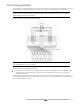
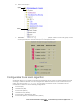
Ports on the switch
The following table describes the Ethernet ports of the switch, including the port name and function.
NOTE: The actual mapping of switch ports to NIC interfaces is dependant on the operating system
software, the type of server blade, and the enclosure type. For more information, see the N8406-026
10Gb Intelligent L3 Switch User’s Guide.
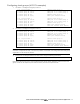
Table 7 Ethernet switch port names
Port number
Port alias
1
Downlink1
2
Downlink2
3
Downlink3
4
Downlink4
5
Downlink5
6
Downlink6
7
Downlink7
8
Downlink8
9
Downlink9
10
Downlink10
11
Downlink11
12
Downlink12
13
Downlink13
14
Downlink14
15
Downlink15
16
Downlink16
17
Mgmt
18
Uplink1
19
Uplink2
20
Uplink3
21
Uplink4
Port trunk groups
When using port trunk groups between 2 switches, you can create an aggregate link operating at up to
40 Gigabits per second, depending on how many physical ports are combined. The switch supports up to
12 trunk groups per switch, each with up to 6 ports per trunk group.
The trunking software detects broken trunk links (link down or disabled) and redirects traffic to other trunk
members within that trunk group. You can only use trunking if each link has the same configuration for
speed, flow control, and auto-negotiation.
Statistical load distribution
In a configured trunk group containing more than one port, the load distribution is determined by
information embedded within the data frame. For IP traffic, the switch will calculate the trunk port to
use for forwarding traffic by implementing the load distribution algorithm on value equals to modulus of
(XOR of last 3 bits of Source and last 3 bits of Destination IP address). For non-IP traffic, the switch will