
User's Manual

NDA-24298 CHAPTER 3
Page 33
Issue 1
CHAPTER 3 OFFICE DATA DESIGN SHEET
Office data design sheets are used to design the configuration and specification of IPX.
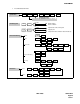
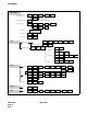
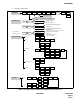
1. Trunking Diagram
The Trunking diagram shows the system configuration and the number of lines.
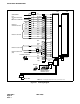
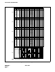
2. Bay Face Layout
The Bay Face layout shows the circuit card mounting slots.
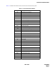
3. Port Location Table
A Port Location table denotes the Line/Trunk circuit cards located in each Universal Slot of PIM.
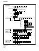
4. Numbering Plan Table
Area Codes for various service features are determined according to the Dial Access Numbering Plan. There are
three types of Dial Access Numbers.
• Station Access Numbers
• Special Service Access Numbers
• Trunk Access Numbers
5. Restriction Tables
1. Service Feature Restriction Class
2. Trunk Restriction Class Table
3. Tenant Restriction Tables