
User's Manual


ND-70185 (E) CHAPTER 7
Page 151
Revision 3.0
TROUBLESHOOTING
3-C PM C-level Infinite Loop (Temporary)
3. 3-C PM C-level Infinite Loop (Temporary)
This message is displayed when the C-level program has been detected as abnormal by the Port Micropro-
cessor (PM) mounted on the FCH (PA-FCHA) card. In this instance, the system performs an appropriate
restart (B-monitor/Initial restart) according to the frequency of the failures. If the frequency exceeds 15
times an hour, it is judged as permanent. See "3-B PM C-level Infinite Loop (Permanent)".
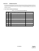
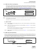
Figure 7-5 3-C PM C-level Infinite Loop (Temporary)
Note:
B-monitor Restart: Ports whose link has already been established remain connected, while ports processing
a call-origination may be released.
Initial Restart: All ports on the circuit card are force released to be placed in idle state.
3.1 Repair Procedure
STEP 1: If the 3-C message has been displayed only once or twice, monitor the failure for a while. Otherwise,
move to STEP 2.
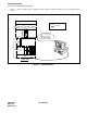
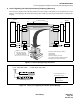
STEP 2: Initialize the indicated FCH (PA-FCHA) card using the MB key. See Figure 7-3 “How to Initialize
the FCH (PA-FCHA) card.”
When the LED on the FCH card lights green, and the related system messages are not displayed, mon-
itor the system for a while. Otherwise move to STEP 3.
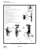
STEP 3: Replace the FCH card, following the procedure listed in Figure 7-4 “How to Replace FCH (PA-
FCHA) card.”
4. 3-D PM Lockup Failure (Permanent)
The CPU sends diagnosis data at periodic intervals to the Port Microprocessor (PM) on FCH (PA-FCHA) cards
in order to monitor the PM. If the CPU cannot receive the return data within a predetermined time period, the
system displays this data. When the failure is detected more than 15 times per hour, the failure is judged as per-
manent. Otherwise, 3-E PM Lockup Failure (Temporary) is displayed.
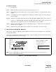
Figure 7-6 3-D PM Lockup Failure (Permanent)
1. xx0x 0000 0000 0000 2. 0000 0000 0000 0000.........
MG
U
G
FCH Mounting Location
FCH Mounting Location
MG: Module Group
U: Unit (0-3)
G: Group (00-23)
PM Restart Type
PM Restart Type
0/1 = B-monitor / Initial Restart
Note
1. xx00 0000 0000 0000 2. 0000 0000 0000 0000.........
MG
U
G
FCH Mounting Location
FCH Mounting Location
MG: Module Group
U: Unit (0-3)
G: Group (00-23)