
User's Manual


ND-70185 (E) CHAPTER 7
Page 155
Revision 3.0
TROUBLESHOOTING
23-S FCH Failure Notification (Detection)
6.2 Repair Procedure
• 13-I (Temporary)
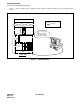
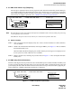
STEP 1: Make sure that the front cable is securely inserted. (See Figure 7-10.)
STEP 2: If this message has been displayed once or twice, monitor the failure for a while. Otherwise, move to
STEP 3.
STEP 3: If 13-J (Recovery) has been displayed after this message, monitor the failure for a while. Otherwise,
move to STEP 4.
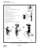
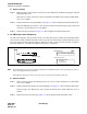
STEP 4: Initialize the indicated FCH (PA-FCHA) card using the MB key. (MB key: Down
➔
Up
➔
Down)
See Figure 7-3. When the LED on the FCH card lights green and the related system messages are not
displayed any more, monitor the system for a while. Otherwise, move to STEP 5.
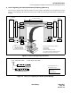
STEP 5: Replace the FCH card, following the procedure listed in Figure 7-4. If the failure exists after card re-
placement, move to STEP 6.
STEP 6: Replace the front cable labeled 10AL (10) FLT CA, since the cable is suspected as faulty.
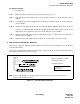
7. 23-S FCH Failure Notification (Detection)
This message is displayed when the FCH (PA-FCHA) card is faulty due to the problems such as an Ethernet
controller initial failure.
The message is displayed in the following format. If this message is displayed, check the related Ethernet cables,
following the procedure listed on the next page.
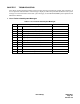
Figure 7-11 23-S FCH Failure Notification
1. xx0x xx00 0000 0000 2. 0000 0000 0000 0000.........
MG
U
G
FCH Mounting Location
FCH Mounting Location
MG: Module Group
U: Unit (0-3)
G: Group (00-23)
FCH CKT No.
Circuit Number of FCH (0 - 7)
FLTINF: Fault Information
Note
FLTINF
FLTINF = 01H: ETHER Controller Initial NG (If this is indicated, replace the FCH (PA-FCHA) card.)
FLTINF = 02H: ETHER Link Failure
Note: