
User's Manual


ND-70185 (E) CHAPTER 4
Page 33
Revision 3.0
INSTALLATION
Key Setting on Circuit Cards
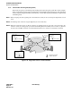
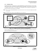
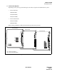
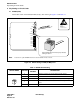
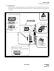
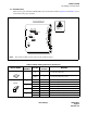
2.2 PA-FCHA (FCH)
Set the switches on the FCH (PA-FCHA) card(s) as shown below. This card has DIP switches, whose key
settings determine the time slots of the Fusion link. In Figure 4-5, CH3 is designated as the D/I channel in
an example.
Figure 4-5 Switch Setting on FCH (PA-FCHA) Card
4
C
0
2
6
A
E
1
2
3
4
OFF
1
2
3
4
5
6
7
8
OFF
1
2
3
4
5
6
7
8
OFF
1
2
3
4
5
67
8
OFF
1
2
3
4
5
67
8
OFF
1
2
3
4
OFF
1
2
3
4
5
6
7
8
OFF
1
2
3
4
5
6
7
8
OFF
1
2
3
4
5
67
8
OFF
1
2
3
4
5
67
8
OFF
4
C
0
2
6
A
E
SW14
SW13
SW12
SW11
SW10
OPE
MB
EST3
EST2
EST1
EST0
PWALM
LYR
LB
LOAD
MNT
10-BASE-T
MODE
DTI
FCH
ATTENTION
Contents
Static Sensitive
Handling
Precautions Required
4
C
0
2
6
A
E
.
.
MODE
Refer to Table 4-2.
FCH (PA-FCHA) Card
FCH (PA-FCHA) Card
SW14
Refer to Table 4-3.
1
2
3
4
OFF
SW13
SW12
SW11
8
9
10
11
12
13
14
15
1
2
3
4
5
67
8
OFF
16
17
18
19
20
21
22
23
1
2
3
4
5
67
8
OFF
Note: Multiple choices are
available.
1
2
3
4
5
6
7
8
0
1
2
3
4
5
6
7
OFF
D / I channel = CH3 (example)
SW10
1
2
3
4
5
6
7
8
OFF
Not Used
ON: T203 Timer = Variable
OFF: T203 Timer = 10 secs. (Standard Setting)
MNT
0 1 2 3
Make-busy-request
Not Used
CH:
CH:
CH:
OFF