
User's Manual

CHAPTER 4 ND-70185 (E)
Page 48
Revision 3.0
INSTALLATION
Connecting Cables
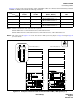
When dual FCH is provided for the HUB dedicated to each internal LANI card (LANI-A: in Slot
00 of each CPR), connect FCH#0 to HUB#0 and FCH#1 to HUB#1.
When your system also uses the external LANI cards (LANI-B in Slot 03 of each CPR), prepare
another set of FCH cards for the HUB dedicated to the external LANI cards. Then, if the FCH is in
dual configuration, connect one FCH to the HUB for No. 0 system of the external LANI, and the
other to the HUB for the No. 1 system of the external LANI.
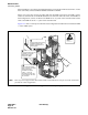
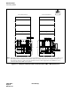
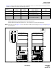
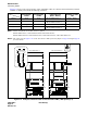
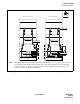
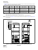
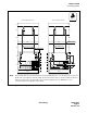
Figure 4-12 shows an example of a HUB in a dual configuration and the FCH card mounted in PIM
1 of the 1 IMG system.
Figure 4-12 Connecting 10 BASE-T Cables (example)
ATTENTION
Contents
Static Sensitive
Handling
Precautions Required
DTI
2
3
3
Connect HUB and FCH using a
10 BASE-T straight cable.
Refer to figures listed on the
following pages.
DTI
FCH
This figure shows an example where HUB is provided in a dual configuration and FCH card is mounted in PIM1 of 1-IMG system.
LANI
LANI
PIM 1
PIM 0
HUB
(PA-M96
)
HUB
(PA-M96)
GT
GT
2
Connect two HUB cards using
a 10 BASE-T cross cable.
(When HUB is in dual
configuration.) Note
-
1
1
Connect the LANI and the
HUB card using a 10 BASE-T
straight cable. Eight
10 BASE-T connectors
(TP0-X - TP7-X) are
furnished on the front edge
of the HUB card. Use one of
the connectors.
1
Note
Note
Note:
This step can be skipped when dual LANIs (LANI-A and LANI-B) are used for each CPU and FCH is
provided in a dual configuration.