AccuSync LCD200VX TM
Index Warning .................................................................................................................... 1 Contents ................................................................................................................. 2 Quick Start ............................................................................................................. 3 Controls ..................................................................................................................
WARNING TO PREVENT FIRE OR SHOCK HAZARDS, DO NOT EXPOSE THIS UNIT TO RAIN OR MOISTURE. ALSO, DO NOT USE THIS UNIT'S POLARIZED PLUG WITH AN EXTENSION CORD RECEPTACLE OR OTHER OUTLETS UNLESS THE PRONGS CAN BE FULLY INSERTED. REFRAIN FROM OPENING THE CABINET AS THERE ARE HIGH VOLTAGE COMPONENTS INSIDE. REFER SERVICING TO QUALIFIED SERVICE PERSONNEL. CAUTION CAUTION: TO REDUCE THE RISK OF ELECTRIC SHOCK, MAKE SURE POWER CORD IS UNPLUGGED FROM WALL SOCKET.
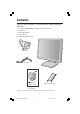
Contents Your new NEC AccuSync™ LCD monitor box* should contain the following: • AccuSync LCD200VX monitor with height adjustable base • Power Cord • Video Signal Cable • User’s Manual • Cable Management Cover Power Cord Video Signal Cable Cable Management Cover TM AccuSync LCD200VX User’s Manual * Remember to save your original box and packing material to transport or ship the monitor. 2 ASLCD200VXmanual062204.
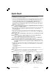
Quick Start To attach the LCD monitor to your system, follow these instructions: 1. Turn off the power to your computer. 2. For the PC or MAC with DVI digital output: Connect the DVI signal cable (not included) to the connector of the display card in your system (Figure A.1). Tighten all screws. For the PC with Analog output: Connect the 15-pin mini D-SUB signal cable to the connector of the display card in your system (Figure A.2). Tighten all screws.
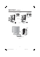
Quick Start –continued Input2 (DVI) Input1 (D-Sub) Input1 (D-Sub) Cable cover Figure C.1 vacation switch power button Figure D.1 4 ASLCD200VXmanual062204.
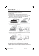
Quick Start –continued Raise and Lower Monitor Screen To raise or lower screen, place hands on each side of the monitor and lift or lower to the desired height (Figure RL.1). NOTE: Handle with care when raising or lowering the monitor screen. Figure RL.1 Tilt Swivel Grasp top and bottom sides of the monitor screen with your hands and adjust the tilt as desired (Figure TS.1). Grasp both sides of the monitor screen with your hands and adjust the swivel as desired (Figure TS.2).
Quick Start –continued Remove Monitor Stand for Mounting To prepare the monitor for alternate mounting purposes: 1. Disconnect all cables. 2. Place hands on each side of the monitor and lift up to the highest position. 3. Place monitor face down on a non-abrasive surface. (Place the screen on a 51 mm/ 2.0 inch platform so that the stand is parallel with the surface.) (Figure S.1). 4. Adjust the stand into a 30 degree angle (Figure S.2). 51 mm Figure S.2 Figure S.1 5.
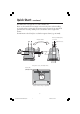
Quick Start –continued This LCD monitor is designed for use with a flexible arm. Please use the attached screws (4pcs) as shown in the picture when installing. To meet the safety requirements, the monitor must be mounted to an arm which guaranties the necessary stability under consideration of the weight of the monitor. The LCD monitor should only be used with an approved arm (e.g. GS mark). Thickness of Bracket (Arm) Replace Screws 2.0~3.2mm Tighten all screws.
Controls OSM® (On-Screen Manager) control buttons on the front of the monitor function as follows: To access OSM menu, press any of the control buttons ( <, >, –, +, EXIT). To change signal input, press the SELECT button. NOTE: OSM must be closed in order to change signal input. Menu EXIT Exits the OSM controls. Exits to the OSM main menu. Moves the highlighted area left/right to select control menus. Moves the highlighted area up/down to select one of the controls.
Controls Tools 1 SHARPNESS: This function is digitally capable to keep crisp image at any timings. It is continuously adjustable to get distinct image or soft one as you prefer, and set independently by different timings. The number of adjustment steps is different depending on whether EXPANSION Mode is OFF, FULL or ASPECT (1600 x 1200 is OFF Mode). EXPANSION MODE: Sets the zoom method. FULL: The image is expanded to 1600 x 1200, regardless of the resolution.
Controls –continued Information DISPLAY MODE: Indicates the current display resolution and frequency setting of the monitor. MONITOR INFO.: Indicates the model and serial numbers of your monitor. OSM® Warning: OSM Warning menus disappear with Exit button. NO SIGNAL: This function gives a warning when there is no signal present. After power is turned on or when there is a change of input signal or video is inactive, the No Signal window will appear.
Recommended Use Safety Precautions and Maintenance FOR OPTIMUM PERFORMANCE, PLEASE NOTE THE FOLLOWING WHEN SETTING UP AND USING THE ACCUSYNC LCD COLOR MONITOR: • DO NOT OPEN THE MONITOR. There are no user serviceable parts inside and opening or removing covers may expose you to dangerous shock hazards or other risks. Refer all servicing to qualified service personnel. • Do not spill any liquids into the cabinet or use your monitor near water.
Recommended Use –continued CORRECT PLACEMENT AND ADJUSTMENT OF THE MONITOR CAN REDUCE EYE, SHOULDER AND NECK FATIGUE. CHECK THE FOLLOWING WHEN YOU POSITION THE MONITOR: • For optimum performance, allow 20 minutes for warm-up. • Adjust the monitor height so that the top of the screen is at or slightly below eye level. Your eyes should look slightly downward when viewing the middle of the screen. • Position your monitor no closer than 16 inches and no further away than 28 inches from your eyes.
Specifications Monitor Specifications AccuSync™ LCD200VX Monitor Notes LCD Module Diagonal : Viewable Image Size : Native Resolution (Pixel Count) : 20.1 inch 20.1 inch 1600 x 1200 Active matrix; thin film transistor (TFT) liquid crystal display (LCD); 0.255 mm dot pitch; 250cd/m2 white luminence; 400:1 contrast ratio, typical Input Signal Video : Sync : ANALOG 0.7 Vp-p/75 Ohms Separate sync. TTL Level Horizontal sync. Positive/Negative Vertical sync.
Features Reduced Footprint: Provides the ideal solution for environments requiring superior image quality but with size and weight limitations. The monitor’s small footprint and low weight allow it to be moved or transported easily from one location to another. AccuColor® Control Systems: Six color presets select the desired color setting (sRGB and NATIVE color presets are standard and cannot be changed). R,G,B: Increases or decreases Red, Green or Blue color depending upon which is selected.
Troubleshooting No • • • • • picture The signal cable should be completely connected to the display card/computer. The display card should be completely seated in its slot. Check the Vacation Switch should be in the ON position. Front Power Switch and computer power switch should be in the ON position. Check to make sure that a supported mode has been selected on the display card or system being used. (Please consult display card or system manual to change graphics mode.
References NEC-Mitsubishi Monitor Customer Service & Support Customer Service and Technical Support: (800) 632-4662 Fax: (800) 695-3044 Parts and Accessories/Macintosh Cable Adapter: (888) NEC-MITS [888-632-6487] Customer Service Policies & Processes: http://www.necmitsubishi.com/ css/ServicePolicies/ServicePolicies.htm Online Technical Support Knowledge Base: http://www.necmitsubishi.com/ css/knowledgebase.cfm Customer Service & Technical Support Email: http://www.necmitsubishi.com/ css/techform.
Limited Warranty NEC-Mitsubishi Electronics Display of America, Inc. (hereinafter “NMD-A”) warrants this Product to be free from defects in material and workmanship and, subject to the conditions set forth below, agrees to repair or replace (at NMD-A’s sole option) any part of the enclosed unit which proves defective for a period of three (3) years from the date of first consumer purchase. Spare parts are warranted for ninety (90) days.
TCO’99 Congratulations! You have just purchased a TCO’99 approved and labelled product! Your choice has provided you with a product developed for professional use. Your purchase has also contributed to reducing the burden on the environment and also to the further development of environmentally adapted electronics products.
TCO’99 –continued accumulative* processes. Flame retardants have been found in human blood and researchers fear that disturbances in foetus development may occur. TCO’99 demand requires that plastic components weighing more than 25 grams must not contain flame retardants with organically bound chlorine and bromine. Flame retardants are allowed in the printed circuit boards since no substitutes are available. Lead** Lead can be found in picture tubes, display screens, solders and capacitors.
20 ASLCD200VXmanual062204.
AVERTISSEMENT AFIN D’ÉVITER TOUT RISQUE D’INCENDIE OU D’ÉLECTROCUTION, NE PAS EXPOSER CET APPAREIL À LA PLUIE OU À L’HUMIDITÉ. NE PAS UTILISER LA FICHE D’ALIMENTATION POLARISÉE AVEC UNE PRISE DE CORDON DE RALLONGE OU AUTRE PRISE SAUF SI LES BROCHES PEUVENT ÊTRE ENTIÈREMENT INTRODUITES. NE PAS OUVRIR LE BOÎTIER, LEQUEL CONTIENT DES COMPOSANTS À HAUTE TENSION. CONFIER TOUS TRAVAUX À DU PERSONNEL TECHNIQUE QUALIFIÉ.
Contenu La boîte* de votre nouveau moniteur NEC AccuSync™ contient : • • • • Moniteur AccuSync LCD200VX avec sa base ajustable en hauteur Cordon d'alimentation Câble pour le signal vidéo Manuel de l’utilisateur • Un cache-câbles Cordon d'alimentation Câble pour le signal vidéo Un cache-câbles TM AccuSync LCD200VX Manuel de l’utilisateur * Ne pas oublier de conserver la boîte et le matériel d'emballage d'origine pour transporter ou expédier le moniteur. 22 ASLCD200VXmanual062204.
Mise en marche rapide Pour raccorder le moniteur LCD au système,suivez les directives ciaprès: 1. Mettez l’ordinateur hors tension. 2. Pour un PC ou un Mac équipé d’une sortie numérique DVI: Branchez le câble DVI-D -DVI-D (non fourni) au connecteur de la carte graphique de votre ordinateur (Figure A.1). Serrez toutes les vis. Pour un PC équipé d’une sortie analogique: Branchez le câble de signal mini-connecteur D-SUB à 15 broches-DVI au connecteur de la carte graphique de votre système (Figure A.2).
Mise en marche rapide (suite) Input1 (D-Sub) Input1 (D-Sub) Input2 (DVI) Input2 (DVI) Un cache-câbles Figure C.1 Interrupteur de vacances Figure D.1 Bouton d’alimentation 24 ASLCD200VXmanual062204.
Mise en marche rapide (suite) Levez et baissez l’écran du moniteur Pour lever ou baisser l’écran, placez les mains de chaque côté du moniteur et positionnez-le à la hauteur de votre choix. (Figure RL.1). NOTA: Manipule sur soin quand augmentant ou l’écran diminuant écran. Figure RL.1 Incliner Pivoter Mettez vos mains sur les côtés inférieur et supérieur de l'écran et réglez l'inclinaison comme désirée (Figure TS.1).
Mise en marche rapide (suite) Enlevez le support du moniteur pour le montage Pour préparer le moniteur à des fins de montage différents : 1. Débranchez tous les câbles. 2. Placez les mains de chaque côté du moniteur en le soulevant dans sa position la plus haute. 3. Placez le moniteur avec l’écran vers le bas sur une surface non abrasive. (Placez le moniteur sur une plateforme de 51 mm/2,0 pouces de façon à ce que le support soit parallèle à la surface.) (Figure S.1). 4.
Mise en marche rapide (suite) Ce moniteur LCD a été conçu pour être utilisé avec un bras flexible. Utiliser les vis fournies (4pièces) lors de l’installation comme indiqué sur la figure. Le moniteur doit être installé sur un bras garantissant la stabilité nécessaire correspondant au poids du moniteur. Ce moniteur LCD ne peut être unilisé qu’ avec un bras homoloqué (par ex. marque GS).
Commandes Les boutons de réglage OSM® situés sur l’avant du moniteur fournissent les fonctions suivantes : Pour accéder au menu OSM, appuyez sur une des touches de commande ( <, > , –, +, EXIT). Pour changer l’entrée du signal, appuyez sur le bouton SELECT. REMARQUE: Le menu OSM doit être fermé pour pouvoir modifier le signal d’entrée. Menu principal EXIT Quitte les commandes OSM. Revient au menu principal OSM.
Commandes (suite) Système de contrôle des couleurs AccuColor® Six colore prérégle sélectionner la désiré couleur mettant (sRGB et NATIVE couleur prérégle sommes standards et cannot être transformé). R, V, B: Augmente ou diminue le niveau des couleurs rouge, vert ou bleu, suivant celui qui a été sélectionné. Le changement de couleur apparraît à l’écran et le sens (augmentation ou diminution) est indiqué par les barres de couleur. Native: Originale couleur nrésenta par le LCD panel qu’est unadjustable.
Commandes (suite) fenêtre s’ouvrira a l’écran et vous indiquera que les r´églages ne sont pas accessibles. Pour verrouiller, appuyer sue les touches SELECT et “+” simultanément. Pour déverrouiller, appuyer sur les touches SELECT et “+” simultanément. ERREUR RESOLUTION: La résolution optimale est 1600 x 1200. Lorsque ON est sélectionné pour cette fonction, le message Notification de résolution apparaît de 30 secondes après la non reconnassance du signal d’entrée en tant que signal 1600 x 1200.
Usage recommandé Consignes de sécurité et d’entretien POUR UN FONCTIONNEMENT OPTIMAL, PRIÈRE DE NOTER CE QUI SUIT POUR LE RÉGLAGE ET L'UTILISATION DU MONITEUR COULEUR ACCUSYNC™ LCD : • NE PAS OUVRIR LE MONITEUR. Aucune pièce intérieure ne nécessite l'intervention de l'utilisateur, et l'ouverture ou la dépose des couvercles peut entraîner des risques de décharges électriques dangereuses ou d'autres risques. Confier tous travaux à du personnel technique qualifié.
Usage recommandé (suite) LA MODIFICATION DE LA POSITION ET DU RÉGLAGE DU MONITEUR PEUT RÉDUIRE LA FATIGUE DES YEUX, DES ÉPAULES ET DE LA NUQUE. OBSERVER LES DIRECTIVES CI-APRÈS LORS DU POSITIONNEMENT DU MONITEUR : • Pour une performance optimale, laissez le moniteur se réchauffer pendant 20 minutes. • Régler la hauteur du moniteur de sorte que le dessus de l'écran soit au niveau ou légèrement en-dessous du niveau des yeux.
Fiche technique Caractér. techn. du moniteur Moniteur Remarques AccuSync™ LCD200VX Module LCD 20,1 po 20,1 po 1600 x 1200 Diagonale : Surface utile : Résolution (nombre de pixels) : Signal d'entrée Vidéo : Sync : ANALOGIQUE 0,7 Vp-p/75 Ohms Entrée numérique: DVI Synchro séparée niveau TTL. Positif/négatif sync. horizontale Positif/négatif sync. verticale Sync.
Fonctions Encombrement réduit : Constitue la solution idéale pour les environnements qui nécessitent une image de haute qualité et un encombrement et un poids limités. L’encombrement réduit et le faible poids du moniteur permettent de le déplacer ou de le transporter rapidement d’un point à un autre. Système de commande AccuColor® : Six que couleur prérégle sélectionner que couleur color mettant le désiré (sRGB et NATIVE prérégle sommes standards et cannot être transformé).
Dépannage Pas • • • • d'image Le câble vidéo doit être bien connecté à la carte d'affichage et à l’ordinateur. La carte d'affichage doit être insérée à fond dans son logement. Vérifiez que l’interrupteur de vacances soit sur la position MARCHE. Les interrupteurs d’alimentation du moniteur à l’avantet de l’ordinateur doivent être sur la position MARCHE.
Références Service à la clientèle et assistance technique du moniteur MEC-Mitsubishi Service à la clientèle et assistance technique: (800) 632-4662 Télécopieur: (800) 695-3044 Pièces et accessoires/adaptateur de câble Macintosh: Politiques et processus du service à la clientèle: Base de connaissance de l’assistance technique en lign: Adresse électronique du service à la clientèle et de l’assistance technique: (888) NEC-MITS [888-632-6487] http://www.necmitsubishi.com/ css/ServicePolicies/ServicePolicies.
Garantie limitée NEC-Mitsubishi Electronics Display of America, Inc. (ci-après «NMD-A») garantit que ce produit est exempt de vice de fabrication et de main-d’oeuvre et, selon les conditions énoncées ci-dessous, accepte de réparer ou remplacer, à sa discrétion, toute pièce de l’appareil concerné qui s’avérerait défectueuse et ce, pendant une période de trois (3) ans à partir de la date d’achat initial. Les pièces de rechange sont garanties pendant quatre-vingt dix (90) jours.
TCO’99 (C’est une traduction de portion Anglaise de TCO’99.) Félicitations! Vous avez acheté un produit qui répond à la directive TCO’99. En choisissant ce produit conçu pour une utilisation professionnelle, vous contribuez aussi à la réduction des effets nuisibles sur l’environnement et aussi au développement continu de produits électroniques respectueux de l’environnement.
TCO’99 (suite) organiquement liés. Les retardateurs de flame sont autorisés dans les cartes à circuits imprimés étant donné qu’aucun substitut n’est encore disponible. Plomb** Le plomb peut être présent dans les tubes cathodiques, les écrans, les soudures et les condensateurs. Le plomb s’attaque au système nerveux et, à doses élevées, entraîne l’intoxication par le plomb. La directive TCO’99 permet l’inclusion du plomb était donné qu’aucun remplacement n’ait encore été mis au point.
40 ASLCD200VXmanual062204.
Série LCD NEC AVIS DE PROPRIÉTÉ EXCLUSIVE ET DE DÉGAGEMENT DE RESPONSABILITÉ Les informations contenues dans ce document, y compris tous les designs et matériel s'y rapportant, sont la propriété de NEC-Mitsubishi Electronics Display of America et/ou ses concédants.
NEC LCD Series PROPRIETARY NOTICE AND LIABILITY DISCLAIMER The information disclosed in this document, including all designs and related materials, is the valuable property of NECMitsubishi Electronics Display of America and/or its licensors, as appropriate, reserve all patent, copyright and other proprietary rights to this document, including all design, manufacturing, reproduction, use and sales rights thereto, except to the extent said rights are expressly granted to others.