本書は製品とともに大切に保管してください Keep this manual carefully. N8103-89 ディスクアレイコントローラ(SATA) ユーザーズガイド Disk Array Controller (SATA) User's Guide 製品をご使用になる前に必ず本書をお読みください。 本書は熟読の上、大切に保管してください。 Make sure you read this manual before using the product. After reading this manual carefully, store it in a safe place.
商標について Microsoft とそのロゴおよび、Windows、MS、MS-DOS は米国 Microsoft 社の米国およびその他の国 における登録商標です。 PromiseTechnology, Inc.とそのロゴおよび、FastTrak、FastBuild Utility、Web-based Promise Array Management(WebPAM)は、米国 Promise 社の登録商標です。 ESMPRO®は、日本電気株式会社の商標です。 Trademarks Microsoft, its logo, Windows, Windows Server and MS-DOS are worldwide registered trademarks of Microsoft Corporation of the U.S.A. Promise Technology, Inc.
まえがき Preface このたびは、本ディスクアレイコントローラをお買い上げいただきまことにありがとうご ざいます。 本書は、N8103-89 ディスクアレイコントローラ(SATA) (以降「本製品」と呼ぶ)を正し く、安全に設置、使用するための手引きです。本製品を取り扱う前に必ずお読みください。 また、本製品を使用する上でわからないこと、不具合が起きたときにもぜひご利用くださ い。本書は、必要な時にすぐに参照できるように必ずお手元に保管してください。 本製品を取り付ける本体装置の取り扱いについての説明は、本体装置のユーザーズガイド を参照してください。また、本製品を取り扱う前に「使用上のご注意」を必ずお読みくだ さい。 なお、本書は和英併記となっております。日本語での説明は i ページから 52 ページを、英 語での説明は i ページから xvi ページおよび、53 ページから 106 ページを参照してくださ い。 Congratulations for your purchase of the Disk Array Controller.
ii このユーザーズガイドは、必要なときすぐに参照できるよう、お手元に置いておくようにしてください。 「使用上のご注意」を必ずお読みください。 Keep this User's Guide at hand for quick reference at anytime necessary. Be sure to read this section carefully. 使用上のご注意 ~必ずお読みください~ NOTES ON USE - Always read the Notes 本製品を安全に正しくご使用になるために必要な情報が記載されています。 The following includes information necessary for proper and safe operation of the product.
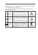
iii 危険に対する注意・表示は次の3種類の記号を使って表しています。それぞれの記号は次 のような意味を持つものとして定義されています。 Precautions against hazards are presented with the following symbols. The individual symbols are defined as follows: 注意の喚起 Attention 行為の禁止 Prohibited Action 行為の強制 Mandatory Action この記号は危険が発生するおそれがあることを表し ます。記号の中の絵表示は危険の内容を図案化したも のです。 This symbol indicates the presence of a hazard. An image in the symbol illustrates the hazard type. この記号は行為の禁止を表します。記号の中や近くの 絵表示は、してはならない行為の内容を図案化したも のです。 This symbol indicates prohibited actions.
iv 本書で使用する記号とその内容 Symbols Used in This Manual and Warning Labels 注意の喚起 Attentions 特定しない一般的な注意・警告を示します。 Indicates a general notice or warning that cannot be specifically identified. 感電のおそれがあることを示します。 Indicates that improper use may cause an electric shock. 高温による障害を負うおそれがあることを示します。 Indicates that improper use may cause personal injury. 発煙または発火のおそれがあることを示します。 Indicates that improper use may cause fumes or fire.
v 安全上のご注意 Safety Indications 本製品を安全にお使いいただくために、ここで説明する注意事項をよく読んでご理解して いただき、安全にご活用ください。記号の説明については巻頭の『安全にかかわる表示に ついて』の説明を参照してください。 This section provides notes on using your product safely. Read this section carefully to ensure proper and safe use of the product. For symbols, see "SAFETY INDICATIONS" provided earlier. <全般的な注意事項> General WARNING 人命に関わる業務や高度な信頼性を必要とする業務には使用しない Do not use the product in life-critical applications or applications requiring high reliability.
vi CAUTION 装置内に水や異物を入れない Keep water or foreign matter away from the server. 装置内に水などの液体、ピンやクリップなどの異物を入れないでください。火災や 感電、故障の原因となります。もし入ってしまったときは、すぐに本体装置の電源 をOFFにして電源コードをACコンセントから抜いてください。分解しないで販売店 または保守サービス会社に連絡してください。 Do not let any form of liquid (water etc.) or foreign matter (e.g., pins or paper clips) enter the server. Failure to follow this warning may cause an electric shock, a fire, or a failure of the server.
vii <電源・電源コードに関する注意事項> Power Supply and Power Cord Use CAUTION 電源がONのまま取り付け・取り外しをしない Disconnect the power cord(s) before installing or removing the product in/from the server. 本体装置への取り付け・取り外しの際や、周辺機器との接続の際は必ず主電源に接 続している電源コードをACコンセントから抜いてください。電源コードがACコンセ ントに接続されたまま取り付け・取り外しや接続をすると感電するおそれがありま す。 Make sure to power off the server and disconnect the power cord(s) from a power outlet before installing/removing the product in/from the server, or connecting with the peripheral devices.
viii <設置・移動・保管・接続に関する注意事項> Installation, Relocation, Storage, and Connection CAUTION プラグを差し込んだままインタフェースケーブルの取り付けや取り外しをしない Do not connect any interface cable with the power cord of the server plugged to a power source. インタフェースケーブルの取り付け/取り外しは本体装置の電源コードをコンセン トから抜いて行ってください。たとえ電源をOFFにしても電源コードを接続したま まケーブルやコネクタに触ると感電したり、ショートによる火災を起こしたりする ことがあります。 Make sure to power off the server and unplug the power cord from a power outlet before connecting/disconnecting any interface cable to/from the server.
ix CAUTION 腐食性ガスの存在する環境で使用または保管しない Do not use or store the product in the place where corrosive gases exist. 腐食性ガス(二酸化硫黄、硫化水素、二酸化窒素、塩素、アンモニア、オゾンなど) の存在する環境に設置し、使用しないでください。 また、ほこりや空気中に腐食を促進する成分(塩化ナトリウムや硫黄など)や導電 性の金属などが含まれている環境へも設置しないでください。装置内部のプリント 板が腐食し、故障および発煙・発火の原因となるおそれがあります。もしご使用の 環境で上記の疑いがある場合は、販売店または保守サービス会社にご相談ください。 Make sure not to locate or use the server in the place where corrosive gases (sulfur dioxide, hydrogen sulfide, nitrogen dioxide, chlorine, ammonia, ozone, etc) exist.
x <お手入れに関する注意事項> Cleaning and Working with the Product WARNING 自分で分解・修理・改造はしない Do not disassemble, repair, or alter the server. 本製品の分解や、修理・改造は絶対にしないでください。装置が正常に動作しなく なるばかりでなく、感電や火災の危険があります。 Never attempt to disassemble, repair, or alter the product on any occasion. Failure to follow this instruction may cause an electric shock or fire as well as malfunctions of the product. プラグを差し込んだまま取り扱わない Disconnect the power plug before accessing inside the server.
xi <運用中の注意事項> During Operation CAUTION 雷がなったら触らない Avoid contact with the server during thunderstorms. 雷が鳴りだしたら、本製品内蔵の本体装置には、触れないでください。感電するお それがあります。 Disconnect the power plug from the outlet when a thunderstorm is approaching. If it starts thundering before you disconnect the power plug, do not touch any part of the server containing the product. Failure to follow this warning may cause an electric shock. ペットを近づけない Keep animals away from the server.
xii 使用上のご注意 ~装置を正しく動作させるために~ 本製品を使用するときに注意していただきたいことを次に示します。これらの注意を無視 して、本製品を使用した場合、資産(データやその他の装置)が破壊されるおそれがあります ので必ずお守りください。 本製品は Express5800 シリーズに Serial-ATA(SATA)機器を接続するためのディ スクアレイコントローラです。他の目的では使用しないでください。 本製品は大変デリケートな電子装置です。本製品を取り扱う前に、本体装置の金 属フレーム部分などに触れて身体の静電気を逃がしてください。本製品の取り扱 いは端の部分を持ち、表面の部品やコネクタと接続する部分には触れないように してください。また、本製品を落としたり、ぶつけたりしないでください。 本製品には、同一規格のハードディスクドライブ(以降「HDD」と呼ぶ)を接続 してください。 本製品に接続可能な本体装置、増設用 HDD ケージ、HDD については、お買い求 めの販売店にお問い合わせください。 本製品は、他の PCI ボード(ディスクアレイコントロー
xiii 本書について This Manual 本書は、Windows などのオペレーティングシステムやキーボード、マウスといった一般的 な入出力装置などの基本的な取り扱いについて十分な知識を持ったユーザを対象として記 載されています。 The guide is intended for persons who are familiar with operating systems including Windows and fundamental operations of general-purpose I/O devices including the keyboard and mouse. <本書の記号について> Text Conventions 本書の中には安全に関わる注意記号の他に次の3種類の記号を使用しています。それぞれ の記号は次のような意味をもつものとして定義されています。 The following conventions are used throughout this User's Guide.
xiv 第三者への譲渡について Transfer to Third Party 本製品を第三者に譲渡(または売却)する時には、必ず本書を含む全ての添付品をあわせ て譲渡(または売却)してください。 Make sure to provide this manual along with the product to a third party.
xv 廃棄について Disposal 本製品の廃棄については、各自治体の廃棄ルールに従って分別廃棄して下さい。詳しくは、 各自治体にお問い合わせ下さい。 Dispose of the product according to all national laws and regulations.
xvi 本書で使用する略称 Abbreviations 正 式 名 称 Formal title 略 称 Abbreviation N8103-89 ディスクアレイコントローラ(SATA) ユーザーズガイド N8103-89 Disk Array Controller (SATA) User’s Guide N8103-89 ディスクアレイコントローラ(SATA) N8103-89 Disk Array Controller (SATA) 本書 this manual N8103-93 増設バッテリ(SATA) N8103-93 Additional DAC Battery (SATA) N8154-01 増設用 HDD ケージ(S-ATA) N8154-01F S-ATA HDD Cage N8154-09 増設用 HDD ケージ(SATA2) N8154-09F SATA2 HDD Cage Web-based Promise Array Manager オペレーションシステム Operation System ハードディスクドライブ Hard disk drive 本製品またはディスクアレイ
xvii 目 次 まえがき Preface ......................................................................................................................... i 使用上のご注意 ~必ずお読みください~ NOTES ON USE - Always read the Notes -.................................................................... ii 本書で使用する記号とその内容 Symbols Used in This Manual and Warning Labels ................ iv 安全上のご注意 Safety Indications.............................................................................................. v 使用上のご注意 ~装置を正しく動作させるために~ ....
xviii 第 3 章 本製品の機能について .......................................................................................... 21 1.リビルド...................................................................................................................................... 21 1-1.マニュアルリビルド(手動リビルド)..................................................................................... 21 1-2.オートリビルド(自動リビルド)............................................................................................ 21 2.メディアパトロール..............
第 1 章 概要 本製品を初めてお使いになる場合は、この章からお読みください。 ここでは、本製品の運用上必ずお守りしていただきたい事項、ならびに、本製品の特徴と ハードウェアのセットアップについて説明します。 1.運用上のご注意~必ずお守りください~ 本製品を安全に運用していただくため、以下の注意事項をお守りください。 1-1.
2 1-2.
3 2.仕様 項 目 仕 様 備 SATA コネクタ数 キャッシュ容量 PCI バス PCI コネクタ 最大 PCI バス転送レート デバイスインターフェース 最大データ転送レート RAID レベル 本体装置への最大搭載数 最大 HDD 接続台数 最大ロジカルドライブ数 外形寸法 フルハイト PCI ブラケット使用時 ロープロファイル PCI ブラケット使用時 質量 動作電圧 消費電力(MAX) 内部 4 チャネル 64MB 動作環境 温度 湿度 PCI2.3 準拠 ユニバーサル/32Bit 266MB/sec 考 SATA Signal: 7pin 66MHz Serial ATA Generation1 対応 150MB/sec 0, 1, 5, 10 1枚 4台 8 1 チャネルに HDD1 台接続 121(幅)x180(長さ)x22(高)mm 81(幅)x180(長さ)x22(高)mm 約 0.09kg 5V 5.3W 10°C~35°C 20%~80% 3.3V/1.044A 3.3V/0.458A(SDRAM) 1.8V/0.
4 3.
5 4.
6 1 チャネル 1~4(Port 1~4) SATA デバイス機器を接続するためのコネクタです。 チャネル 2 チャネル 4 チャネル 3 チャネル 1 2 HW ラベル 本製品の管理レビジョンを表示しているラベルです。 REV XXX 3 増設バッテリ用コネクタ N8103-93 増設バッテリ(SATA)を接続するためのコネクタです。 4 I2C コネクタ I2C ケーブルを接続するコネクタです。 5 N コードラベル 本製品のNコードを表示しています。 N8103-89 6 HDD LED コネクタ 本体装置の DISK ACCESS ランプを点灯させるために、本体装置のマザーボードと接続 します。 7 PCI コネクタ 本体装置の PCI スロットに接続するコネクタです。
7 5.
8 5-1.セットアップの準備 セットアップを行う前に、以下の注意事項をご覧ください。 本製品は、本体装置1台に対して1枚のみ実装可能です。複数枚の実装は できません。 PCI スロットには、本体装置により実装制限がある場合があります。取 り付ける前に本体装置のユーザーズガイドを確認してください。 本製品に接続するHDD は、同一規格のHDD を使用してください。本製 品に接続可能なHDD については、お買い求めの販売店にご確認くださ い。 本製品は、他のPCI ボード(ディスクアレイコントローラ、ミラーリング ボード、SCSI コントローラ等)の混在使用を制限している場合がありま す。本製品を他のPCI ボードと混在してご使用になる場合は、混在が可 能かどうかお買い求めの販売店にご確認ください。 1. すべてのアプリケーションを終了し、OS のシャットダウン処理を行います。 2. POWER スイッチを押して本体装置の電源をOFFにします。 3. 本体装置の電源ユニットに接続している全ての電源コードをコンセントから抜き ます。 4.
9 5-2.ブラケットの選択・取り付け 本製品はフルハイト PCI ブラケットが取り付けられています。ロープロファイルに対応し た PCI スロットに本製品を取り付ける場合は、添付のロープロファイル PCI ブラケットに 交換する必要があります。 1. フルハイト PCI ブラケットと本製品を固定しているネジ(2 本)を取り外します 2. フルハイト PCI ブラケットを取り外します。 3. ロープロファイル PCI ブラケットを取り付けます。 4.
10 5-3.本製品の取り付け 1. 本製品を取り付ける PCI スロットの位置を確認し、対応する増設スロットカバー を取り外します。 取り外した増設スロットカバーは大切に保管してください。外したネジ は、本製品の取り付けに使用しますので、なくさないでください。 本製品は、PCI ホットプラグ機能には対応していません。本製品を抜き 差しする場合は、必ず本体装置の電源をOFF にして、電源コードをコン セントから抜いてください。 PCI スロットには、本体装置により実装制限がある場合があります。取り 付ける前に本体装置のユーザーズガイドをご覧ください。 2. 本製品を PCI スロットにしっかりと差し込み、固定します。ネジで固定する場合 は、増設スロットカバーを取り外した時のネジを使用して固定します。 本製品 (ディスクアレイコントローラ) ネジ 3.
11 5-4.
12 5-5.増設用 HDD ケージの取り付け 増設用 HDD ケージを使用する場合は、増設用 HDD ケージに添付されているユーザーズ ガイドの手順に従って取り付けます。 5-6.
13 5-7.ケーブルのフォーミング SATA ケーブルおよび I2C ケーブルを固定するため、以下の手順に従ってケーブルを フォーミングします。 1.
14 2.
15 第 2 章 RAID について ここでは、本製品がサポートしている RAID 機能について説明します。 1. RAID の概要 1-1.
16 1-3.ロジカルドライブ(Logical Drive) ロジカルドライブは複数の HDD のグループを表すもので、OS からは物理ドライブとして 認識されます。本製品の設定可能なロジカルドライブの数は、HDD を 4 台実装した場合で 最大 8 個になります。 次の図は本製品(ディスクアレイコントローラ)に HDD を 4 台接続し、3 台でロジカルドラ イブを作成、残りの 1 台をホットスペアディスクに設定した構成例です。 ディスクアレイコントローラ ロジカルドライブ1 チャネル1 (Port 1) LD 1-1 チャネル 2 (Port 2) LD 1-2 チャネル 3 (Port 3) LD 1-3 LD x-x : ロジカルドライブに割り 当てられた HDD Spare : ホットスペアディスク チャネル 4 (Port 4) Spare 1-4.パリティ(Parity) 冗長データのことです。複数台の HDD のデータから 1 セットの冗長データを生成します。 生成された冗長データは、HDD が故障したときにデータの復旧のために使用されます。 1-5.
17 1-6.
18 2. RAID レベル 本製品がサポートしている RAID レベルについて詳細な説明をします。 2-1. RAID レベルの特徴 各 RAID レベルの特徴は下表の通りです。 レベル 機 RAID0 能 冗長性 特 徴 ストライピング なし RAID1 ミラーリング あり RAID5 データおよび冗長データ のストライピング あり RAID10 ストライピングとミラー リングの組合せ あり データ読み書きが最も高速 容量が最大 容量=HDD1 台の容量×HDD 台数 HDD が 2 台必要 容量=HDD1 台の容量 HDD が 3 台以上必要 容量=HDD1 台の容量×(HDD 台数-1) HDD が 4 台必要 容量=HDD1 台の容量×2 2-2.
19 2-3.「RAID1」について 1 つの HDD に対してもう 1 つの HDD へ同じデータを記録する方式です。この方式を「ミ ラーリング」と呼びます。 1 台の HDD にデータを記録するとき同時に別の HDD に同じデータが記録されます。一方 の HDD が故障したときに同じ内容が記録されているもう一方の HDD を代わりとして使 用することができるため、システムをダウンすることなく運用できます。 アレイコントローラ Disk 1 Disk 2 ストライプ 1 ストライプ 1 ストライプ 2 ストライプ 2 2-4.
20 2-5.
21 第 3 章 本製品の機能について 本製品が持つ機能を説明します。 1.リビルド リビルド(Rebuild)は、ハードディスクドライブ(以降「HDD」と呼ぶ)に故障が発生した場 合に、故障した HDD のデータを復旧させる機能です。 『RAID1』や『RAID5』 、 『RAID10』 など、冗長性のあるロジカルドライブ対して実行することができます。 1-1.マニュアルリビルド(手動リビルド) 本製品の管理ユーティリティ Web-based Promise Array Manager(以降「WebPAM」と呼ぶ) を使用し、手動で実施するリビルドです。HDD を選択してリビルドを実行することができ ます。 詳しい操作方法については、本製品添付の CD-ROM「S-ATA Array Management Software」 内のオンラインマニュアル「Web-based Promise Array Manager ユーザーズガイド」をご 覧ください。 1-2.
22 リビルドを実行する場合は、以下の点に注意してください。 リビルドに使用するHDD は、故障したHDD と同一容量、同一回転数、 同一規格のものを使用してください。 リビルド中は負荷がかかるため、処理速度は低下します。 リビルド中は、本体装置のシャットダウンやリブートを実施しないでく ださい。万が一、停電などの不慮な事故でシャットダウンしてしまった 場合、速やかに電源の再投入を行ってください。自動的にリビルドが再 開されます。 ホットスワップリビルドを実行するためには、 増設用HDD ケージが必要 です。 故障したHDD を抜いてから新しいHDD を実装するまでに、90秒以上の 間隔をあけてください。 ホットスワップリビルドが動作しない場合は、マニュアルリビルドを実 行してください。
23 2.
24 3.
25 4.
26 例) RAID5 のロジカルドライブのエクスパンション 以下は、80GB HDD×3 台で構成された RAID5 のロジカルドライブに、80GB HDD を 1 台追加する場合の例です。 ロジカルドライブ(RAID5) 80GB 80GB 【実行前】 容量 = 160GB 80GB 80GB エクスパンション実行 ロジカルドライブ(RAID5) 【実行後】 容量 = 240GB 80GB 80GB 80GB 80GB
27 第 4 章 ランプ表示について 本製品は、増設用 HDD ケージと接続することでハードディスクドライブ(以降「HDD」 と呼ぶ)のアクセス状態や、故障やリビルド動作中などのステータスを確認することがで きます。また、本体装置添付の LED ケーブルを接続することで、アクセス時に本体装置前 面の DISK ACCESS ランプを点滅させることができます。 1.
28 2.
29 第 5 章 ロジカルドライブの作成 ここでは本製品のコンフィグレーションユーティリティ「FastBuild Utility」について説明 します。 1.FastBuild Utility を使用する前に 「FastBuild Utility」を使用する前に、サポート機能および注意事項をご覧ください。 1-1.
30 1-2.
31 (2) サポート外のスプリット構成 (2-1)異なる RAID レベルが作成された構成(その 1) アレイコントローラ LD1-1 80GB LD1-2 80GB LD1-3 80GB RAID5 LD サイズ: 160GB LD2-1 40GB LD2-2 40GB LD2-3 40GB RAID0 LD サイズ: 120GB HDD 2 (120GB) HDD 3 (120GB) HDD 1 (120GB) (2-2)異なる RAID レベルが作成された構成(その 2) アレイコントローラ LD1-1 80GB LD1-2 80GB LD1-3 80GB LD1-4 80GB RAID5 LD サイズ: 240GB LD3-2 40GB RAID1 LD サイズ: 40GB L RAID1 LD サイズ: 40GB LD2-1 40GB LD2-2 40GB LD3-1 40GB HDD 1 (120GB) HDD 2 (120GB) HDD 3 (120GB) HDD 4 (120GB) (2-3)異なる台数の HDD で作成された構成 ア
32 (2-4)異なる容量の HDD で作成された構成 アレイコントローラ RAID1 LD サイズ: 40GB LD1-1 80GB LD1-2 80GB LD1-1 40GB LD1-2 40GB HDD 1 (120GB) HDD 2 (120GB) LD1-3 80GB LD1-4 80GB HDD 3 (80GB) HDD 4 (80GB) RAID5 LD サイズ: 240GB (2-5)異なる HDD で作成された構成 アレイコントローラ RAID5 LD サイズ: 120GB LD1-1 60GB LD1-2 60GB LD1-3 60GB Free 60GB Free 60GB LD1-1 60GB LD1-2 60GB LD1-3 60GB HDD 2 (120GB) HDD 3 (120GB) HDD 4 (120GB) HDD 1 (120GB) RAID5 LD サイズ: 120GB
33 2. FastBuild Utility の起動とメニュー 2-1. FastBuild Utility の起動 以下の POST 画面が表示されたら+キーを押して FastBuild Utility を起動します。 【POST 画面イメージ(ロジカルドライブ未設定時)】 FT SX4100 (tm) BIOS Version x.x.xxxx.xx (c) xxxx-xxxx Promise Technology, Inc. All rights reserved. Installed ECC DIMM: 64M No Array is defined... Press to enter FastBuild (tm) Utility...
34 2-2. Main Menu FastBuild Utility を起動すると最初に表示される[Main Menu]画面です。ここから各種設定 を行うため<1>~<4>キーを押して画面を切り換えます。 <1>~<4>キーの入力は、標準キーボードから入力してください。テンキー からの入力は出来ません。 FastBuild (tm) Utility (c) xxxx-xxxx Promise Technology, Inc. [ Main Menu ] View Drive Assignments..............[ 1 ] Define LD...........................[ 2 ] Delete LD...........................[ 3 ] Controller Configuration............[ 4 ] [ Keys Available ] Press 1..
35 2-3. View Drive Assignments [Main Menu]で<1>キーを押すと以下の[View Drive Assignments]画面が表示されます。この 画面では、HDD の情報とロジカルドライブの構成状態を確認することができます。 各チャネルの移動は矢印キー『↑』『↓』で移動します。情報のみの表示な ので設定項目はありません。 HDD を 4 台接続し、2 台で RAID1 のロジカルドライブを 2 個設定し、1 台で RAID0 のロジカルドライブを作成した構成 例) FastBuild (tm) Utility (c) xxxx-xxxx Promise Technology, Inc.
36 [Assignment] HDD のロジカルドライブの構成状態が表示されます。 Assignment 意味 LD x-y 正常に動作可能であり、ロジカルドライブの一部として設定されてい る状態。 『x』はロジカルドライブ番号を示します。 『y』はロジカルドライブ内での HDD の割り当て番号を示します。 「Assignment」が『Free』になっている場合は、以下の 3 通りのディ スクに該当します。 ロジカルドライブに割り当てられていないディスク オフラインになっているディスク スペアディスク Free HDD のモデル名の欄の容量と『Extent x』の欄に表示される容量とでは、 『Extent x』の欄の容量の方が少なく表示されます。これは、モデル名の欄 の容量が使用しているHDD の全容量を表示しているのに対して、『Extent x』の欄の容量は本製品が使用する管理領域を除いた容量を表示しているた めです。
37 2-4. Define LD [Main Menu]で<2>キーを押すと以下の[Define LD Menu]画面が表示されます。 この画面ではロジカルドライブの新規作成および既存のロジカルドライブの情報・ステー タスの確認もできます。 例)HDD3 台での RAID5 構成 FastBuild (tm) Utility (c) xxxx-xxxx Promise Technology, Inc.
38 2-5. Delete LD [Main Menu]で<3>キーを押すと以下の[Delete LD Menu]画面が表示されます。この画面か らロジカルドライブの削除を実行することができます。 例)HDD3 台での RAID5 構成 FastBuild (tm) Utility (c) xxxx-xxxx Promise Technology, Inc. [ Delete LD Menu ] LD LD LD LD LD LD LD LD 1 2 3 4 5 6 7 8 RAID 5 ---------------------- 3 ---------------------- 159866 ------------------------------------ Functional ---------------------- [ Keys Available ] [↑] Up [↓] Down [ESC] Exit [Del or Alt+D] Delete Delete LD(ロジカルドライブの削除)の実行手順 1.
39 2-6. Controller Configuration [Main Menu]で<4>キーを押すと以下の画面が表示されます。 この画面からエラー検出時の起動方法の設定、およびシステムリソースの確認を行うこと ができます。 FastBuild (tm) Utility (c) xxxx-xxxx Promise Technology, Inc.
40 2-7. FastBuild Utility の終了 1. キーを押し[Main Menu]画面まで戻ります。 2. [Main Menu]の表示画面でキーを押すと FastBuild Utility の終了を確認する メッセージが表示されます。 System is going to REBOOT! Are You Sure? Y – Reboot / Any key - Back 3.
41 3.ロジカルドライブの作成 ここでは FastBuild Utility 上でロジカルドライブ作成するときの操作について説明します。 3-1.ロジカルドライブの作成作業フロー ロジカルドライブの 作成開始 FastBuild Utility の起動 既存のロジカル ドライブがある? No Yes ロジカルドライブの 追加? Yes No ロジカルドライブを削除する HDD の接続確認 ロジカルドライブの作成 起動方法の設定 本体装置の再起動 ロジカルドライブの 作成終了 z[Delete LD] 「2-5.
42 3-2.
43 3-3.ロジカルドライブの作成方法 1. FastBuild Utility を起動します。 2. [Main Menu] で<1>キーを押して[View Drive Assignments]を立ち上げます。 FastBuild (tm) Utility (c) xxxx-xxxx Promise Technology, Inc. [ View Drives Assignments ] Channel:ID 1:Mas MAXTOR Extent 2:Mas MAXTOR Extent 3:Mas MAXTOR Extent 4:Mas MAXTOR Extent Drive Model 6Y080MO 1 6Y080MO 1 6Y080MO 1 6Y080MO 1 Capacity (MB) 80001 79933 80001 79933 80001 79933 80001 79933 Assignment Free Free Free Free [ Keys Available ] [↑] Up 3.
44 5. [Main Menu]で<2>キーを押して[Define LD Menu]を立ち上げます。 FastBuild (tm) Utility (c) xxxx-xxxx Promise Technology, Inc. [ Define LD Menu ] LD No LD 1 LD 2 LD 3 LD 4 LD 5 LD 6 LD 7 LD 8 RAID Mode ------------------------- Total Drv ------------------------- Capacity (MB) ----------------------------------------- Status ------------------------- [ Keys Available ] [↑] Up 6.
45 7.
46 8. 設定項目の設定が完了したら、[Devices Assignments]で作成するロジカルドライ ブに使用する HDD を選択します。矢印キー『↑』『↓』で対象の HDD にカーソ ル移動し、キーを押します。[Assignment]の表示が『N』→『Y』に変更 されると HDD がロジカルドライブに割り当てられたことを意味します。 9. ロジカルドライブの設定がすべて完了したら+キーを押して構成情報を 保存します。 10. 「Fast Init」の設定を『ON』に設定した場合、以下のメッセージが表示されます。 Fast Initialization を実施する場合は、再度+ キーを押します。Fast Initialization を実施しない場合は、その他の任意のキー(キーなど)を押しま す。 Fast Initialization Option has been selected. It will erase the MBR data of the disks.
47 13. ロジカルドライブ作成後、以下の[Define LD Menu]画面が表示されます。作成し たロジカルドライブの情報を確認したい場合は、カーソルを対象のロジカルドラ イブに移動しキーを押してください。[View LD Definition Menu]画面が表 示されます。前画面に戻る場合はキーを押します。 FastBuild (tm) Utility (c) xxxx-xxxx Promise Technology, Inc.
48 第 6 章 運用・保守 1.保守サービス 保守サービスは NEC の保守サービス会社、および NEC が指定した保守サービス会社に よってのみ実施されますので、純正部品の使用はもちろんのこと、技術力においてもご安 心の上、ご都合にあわせてご利用いただけます。 なお、お客さまが保守サービスをお受けになる際のご相談は、弊社営業担当または代理店 で承っておりますのでご利用ください。 2.予防保守 2-1.データのバックアップ 万が一の場合に備え、定期的にハードディスクドライブ(以降「HDD」と呼ぶ)内のデータ をバックアップすることをお勧めします。 データのバックアップについては、本体装置のユーザーズガイドをご覧ください。 2-2.
49 3.保守機能について 本製品で以下の保守機能をサポートしています。 Configuration on Disk(COD)機能 リビルド機能 クリティカルブート機能 3-1. Configuration on Disk(COD)機能 Configuration on Disk (COD)機能は、コンフィグレーション情報を HDD 内部に記録する機 能です。この機能により、万一ディスクアレイコントローラが故障し、ディスクアレイコ ントローラの交換を行っても、コンフィグレーション情報が失われることはありません。 ディスクアレイコントローラ交換後、コンフィグレーション情報を HDD から読み込み、 正常に動作させることが可能です。 本製品はコンフィグレーション情報をディスクアレイコントローラ内に保 存しません。コンフィグレーション情報は、すべてHDD 内に記録/保存され ます。 3-2.
50 4.本製品の交換 本装置を交換する際は以下の手順に従ってください。 本体装置の取り扱いについては、本体装置のユーザーズガイドをご覧くださ い。 1. 本体装置の電源を OFF にして、電源コードをコンセントから抜きます。電源が ON になっている場合は、OS のシャットダウン処理を行った後、本体装置の電源 を OFF にして電源コードをコンセントから抜いてください。 2. 本体装置のサイドカバーや部品等を取り外します。 3. 本製品に接続されているケーブル(SATA ケーブル、I2C ケーブル、LED ケーブル) を取り外します。 SATA ケーブルを取り外す前に、本製品のSATA コネクタとSATA ケーブ ルのチャネル番号を確認し、接続構成を必ず控えてください。 4.
51 5.
52 (3)HDD が故障した → 契約されている保守サービス会社、または購入された販売店へ連絡してく ださい。 (4)リビルドが実行できない リビルドするHDD の容量が少なくありませんか? → 故障した HDD と同じ容量のディスクを使用してください。 ロジカルドライブのRAID レベルが、RAID0 ではありませんか? → RAID0 には冗長性がないためリビルドができません。故障した HDD を交 換して、再度ロジカルドライブを作成してください。 WebPAM の設定が正しく設定されていますか? →WebPAM の設定項目の中には、リビルドの動作を制限するものもあります。 詳しくは、本製品添付の CD-ROM「S-ATA Array Management Software」 内のオンラインマニュアル「Web-based Promise Array Manager ユーザー ズガイド」をご覧ください。 (5)メディアパトロールが実行できない HDD が『Free』の状態ではありませんか? → 『Free』ディスクに対しては、メディアパトロールは実行できません。 WebPA
Contents Chapter 1 Overview ........................................................................................................... 55 1. Notes on Use - Always Follow These Notes - ............................................................................ 55 1-1. Installation of WebPAM....................................................................................................... 55 1-2. Preventive Maintenance by Media Patrol/Synchronization .................................................
54 Chapter 5 Creating Logical Drive ....................................................................................... 83 1. Before Using FastBuild Utility..................................................................................................... 83 1-1. Support Functions .............................................................................................................. 83 1-2. Notes on Creation of Logical Drive .....................................................................
55 Chapter 1 Overview Read this chapter first if you use the disk array controller for the first time. This chapter describes the notes you should always follow while you use the card, the features of the card, and the hardware setup. 1. Notes on Use - Always Follow These Notes - Follow the following notes to allow you to use the card safely. 1-1. Installation of WebPAM Install the Web-based Promise Array Manager (called WebPAM hereafter), management utility which manages the card on OS.
56 2. Specification Item Specification Remarks Number of SATA connectors Cache capacity PCI bus PCI connector Maximum PCI bus transfer rate Device interface 4 internal channels 64 MB Conforming to PCI2.
57 3. Features of Disk Array Controller The disk array controller is equipped with four channels of interface connectors conforming to Serial-ATA Generation1. The data transfer rate per channel is up to 150 MB/sec. The card realizes low cost and high performance. The card can be connected to an additional battery to operate in the WriteBack mode, which can improve the access performance further. In addition, the card can be connected to an additional HDD cage to provide the hot-swap feature.
58 4. Names and Functions of Sections This section describes the sections on the card.
59 1 Channel 1 - 4 (Port 1 - 4) These channels allow the card to be connected to SATA devices. Channel 2 Channel 4 Channel 3 Channel 1 2 HW label Indicates the management revision of the card. REV XXX 3 Additional battery connector The connector allows the card to be connected to an additional battery. 4 I2C connector The connector is connected with an I2C cable. 5 N code label Indicates the N code of the card.
60 5. Hardware Setup Install the disk array controller in a server in the following procedure. Check Before the installation, always refer to the User’s Guide of the server. The job flow varies depending on the server type, system configuration, and existence of additional HDD cage. Check the server type and device configuration before the installation to follow the correct flow. Start setup Prepare for setup. Select and install bracket.
61 5-1. Prepare for setup Notice Note the following before the setup. Only a single disk array controller can be installed in a server. Some limitation may be imposed to the installation on the PCI slot depending on the type of the server. Before the installation, check the limitation following the User’s Guide of the server. HDDs to be connected to the card should have the same specification. Contact your service representative for HDDs which can be connected to the card.
62 5-2. Selecting and Installing Bracket The card is previously equipped with a full-height PCI bracket. To install the card on a PCI slot suit to the low profile, the full-height PCI bracket should be replaced with the low-profile PCI bracket coming with the card. 1. Remove the screws (2) fixing the full-height PCI bracket to the card. 2. Remove the full-height PCI bracket. 3. Install the low-profile PCI bracket on the card. 4. Fix the low-profile PCI bracket with the screws (2) removed in step 1.
63 5-3. Installing the Disk Array Controller 1. Confirm the position of the PCI slot in which the disk array controller is installed and remove the corresponding additional slot cover. Notice Save the removed additional slot cover carefully. The removed screw will be used to install the card. Do not lose them. The card does not support the PCI hot-plug feature. Before install or remove the card from the server, always turn off the server and pull out the power cord from the receptacle.
64 5-4. Connecting LED and SATA Cables Connect the LED cable coming with the card to the HDD LED connector. For the connection, see the figure below and the connection table. For the connection to the motherboard, refer to the User’s Guide of the server. If it is hard to connect the LED cable, pull out the card from the PCI slot once and connect the cable to the card. Next, connect a SATA cable to the SATA connector on the card.
65 5-5. Installing Additional HDD Cage To install an additional HDD cage in the server, see the procedure described in the User’s Guide coming with the additional HDD cage. 5-6. Connecting I2C Cable To use the additional HDD cage, connect the card to the cage through the I2C cable coming with the card. Connect the 3-pin connector (white) of the I2C cable to the I2C connector on the card and the 4-pin connector (black) to the additional HDD cage.
66 5-7. Forming Cables To fix the SATA and I2C cables appropriately, form the cables in the following procedure. 1. Attachment of cable clamp Attach the cable clamp coming with the card on the server. Attach the cable clamp at an arbitrary position where cables can be fixed securely. Some servers do no have any area available for the attachment of the cable clamp. If so, bundle cables so that they may not be disordered.
67 2. Cable forming Release the lock of the cable clamp. Bundle the cables to fix them. SATA cable Cable clamp I2C cable After forming the SATA cable, make sure that the cable is not loose and inserted to the mating connector straight.
68 Chapter 2 RAID This chapter describes the RAID features which the disk array controller supports. 1. Overview of RAID 1-1. What is RAID (Redundant Array of Inexpensive Disks)? RAID is an abbreviation for "Redundant Array of Inexpensive Disks." The RAID technology allows more than one hard disk drive (HDD) to be handled collectively. In actual, RAID can configure more than one HDD as a single array (logical drive) to operate the HDDs effectively.
69 1-2. RAID Levels The record mode enabling the RAID feature includes several levels. Among the levels, the disk array controller supports the following levels; RAID 0, RAID 1, RAID 5, and RAID10. The number of HDDs required to create a logical drive varies depending on the RAID level as shown in the table below. RAID level Number of required HDDs Min. Max. RAID 0 RAID 1 RAID 5 RAID 10 1 2 3 4 4 2 4 4 For details of the RAID levels, see "2. RAID Levels" described later in this chapter.
70 1-3. Logical Drive A logical drive is configured with a group of more than one HDD. It is recognized as a physical drive by OS. Up to eight logical drives are permitted by the card when four HDDs are installed in the server. The figure below shows a sample configuration in which the disk array controller is connected with four HDDs, three of which create a logical drive and the remaining HDD is set to a single hot-spare disk.
71 1-6. Hot-Spare Disk The hot-spare disk is prepared as an auxiliary HDD substituting for a defected HDD included in a logical drive which is configured at a redundant RAID level. Detecting a HDD fault, the system disconnects the HDD (or makes it offline) and starts rebuild using the hot-spare disk. The hot-spare disk can be set in two types as listed in the table below. Setting Feature Global Spare Available as a hot-spare disk if a HDD in any logical drive is defected.
72 2. RAID Levels This section details the RAID levels which the disk array controller can support. 2-1. Characteristics of RAID Levels The table below lists the characteristics of the RAID levels.
73 2-3. RAID1 In the RAID1 level, data saved in a HDD is recorded to another HDD without change. The mode is called "mirroring." When data is recorded to a single HDD, the same data is recorded to another HDD. If either of the HDDs is defected, the other HDD containing the same data can substitute for the defected HDD. Thus the system can continue to operate without interruption. Disk array controller Disk 1 Disk 2 Stripe 1 Stripe 1 Stripe 2 Stripe 2 2-4.
74 2-5. RAID10 Data is distributed to HDDs by striping and the stripes are recorded by mirroring. Therefore, RAID10 can realize the disk access performance as high as RAID0 and the reliability as high as RAID1 at a time.
75 Chapter 3 Features of Disk Array Controller This chapter describes the features of the disk array controller. 1. Rebuild If a HDD is defected, the rebuild feature can recover the data in the defected HDD. The rebuild can be applied to redundant logical drives in the RAID1, RID5, or RAID10 level. 1-1. Manual Rebuild The manual rebuild can be done by using WebPAM, the management utility of the disk array controller. Select a HDD and start the rebuild manually.
76 Notice Note the following for the rebuild: The HDD to be used for rebuild should have the same capacity, number of revolutions, and standard as the defected HDD. During rebuild, the processing rate is decreased due to much load. During rebuild, do not shut down or reboot the server. If the server is shut down by an unforeseen accident such as power interruption, turn on the power again as soon as possible. The rebuild is automatically restarted.
77 2. Media Patrol The media patrol gives the read & verify test in the entire area of HDDs. It can be done for all HDDs assigned to logical drives and hot-spare disks. The media patrol allows subsequent defects of HDDs to be detected and repaired. Accordingly, routine media patrol is recommended as preventive maintenance. Routine media patrol can be done by scheduling.
78 3. Synchronization The synchronization checks consistency among logical drives. It is available for redundant logical drives in the RAID1, RAID5, or RAID10 level. Similar to the media patrol, routine synchronization can be done by scheduling. The synchronization can not only check consistency but also repair detected error sectors in the same way as the media patrol. Accordingly, it can be used as preventive maintenance.
79 4. Expansion The expansion adds one or more HDDs to an existing logical drive to increase the capacity of the logical drive. Notice Note the following for the expansion: Before expansion, data backup and synchronization should always be done. During expansion, the processing rate is decreased due to much load. Expansion is unavailable for a logical drive in the critical state. Before the expansion, rebuild should be done to recover logical drive.
80 Ex: Expansion of logical drive in RAID5 The figure below shows an example of adding a single 80GB HDD to a RAID5 logical drive configured with three 80GB HDDs.
81 Chapter 4 Lamp Indications When the disk array controller is connected with an additional HDD cage, it allows you to check the access states of HDDs and several status including that under a failure or rebuild operation. In addition, being connected with the LED cable coming with the server, the disk array controller can blink the DISK ACCESS lamps on the front face of the server in HDD access status. 1.
82 2. Indications of Disk Lamps on Trays Disk lamp Indication Description Green OFF Rapid blink ON during start Does not access to HDD. Access to HDD now. Supplies power to HDD. Does not indicate that HDD is defected. Indicates that HDD is defected or SATA cable is removed. If HDD is defected, replace it with new one and perform rebuild process. Indicates that rebuild process is executed. Umber ON during operation Slow blink Notice Without accesses, the green lamp may blink frequently.
83 Chapter 5 Creating Logical Drive This chapter describes the disk array controller configuration utility "FastBuild Utility." 1. Before Using FastBuild Utility Before using the FastBuild Utility, see the support functions and notes described below. 1-1.
84 1-2. Notes on Creation of Logical Drive Setting hot-spare disk FastBuild Utility cannot set hot-spare disks. To set hot-spare disks, use the disk array controller management utility WebPAM after OS is installed. For free HDDs unassigned to any logical drives, standby rebuild can be done but media patrol cannot. It is recommended to specify such free HDDs as spare disks by using WebPAM.
85 (2) Unsupported split configurations (2-1) Configuration of logical drives in different RAID levels (1) Disk array controller LD1-1 80GB LD1-2 80GB LD1-3 80GB RAID5 LD size: 160GB LD2-1 40GB LD2-2 40GB LD2-3 40GB RAID0 LD size: 120GB HDD 2 (120GB) HDD 3 (120GB) HDD 1 (120GB) (2-2) Configuration of logical drives in different RAID levels (2) Disk array controller LD1-1 80GB LD1-2 80GB LD1-3 80GB LD1-4 80GB RAID5 LD size: 240GB LD3-2 40GB RAID1 LD size: 40GB L RAID1 LD size: 40GB LD2-
86 (2-4) Configuration of logical drives created by HDDs of different capacities Disk array controller RAID1 LD size: 40GB LD1-1 80GB LD1-2 80GB LD1-1 40GB LD1-2 40GB HDD 1 (120GB) HDD 2 (120GB) LD1-3 80GB LD1-4 80GB HDD 3 (80GB) HDD 4 (80GB) RAID5 LD size: 240GB (2-5) Configuration of logical drives created by different HDDs Disk array controller RAID5 LD size: 120GB LD1-1 60GB LD1-2 60GB LD1-3 60GB Free 60GB Free 60GB LD1-1 60GB LD1-2 60GB LD1-3 60GB HDD 2 (120GB) HDD 3 (120GB) H
87 2. Starting and Menus of FastBuild Utility 2-1. Starting FastBuild Utility When the POST screen shown below appears, press the [Ctrl] + [F] keys to start FastBuild Utility. [POST screen image (no setting of logical drive)] FT SX4100 (tm) BIOS Version x.x.xxxx.xx (c) xxxx-xxxx Promise Technology, Inc. All rights reserved. Installed ECC DIMM: 64M No Array is defined... Press to enter FastBuild (tm) Utility...
88 2-2. Main Menu After starting FastBuild Utility, the Main Menu appears first. Then press any of the [1] - [4] keys to display the screen on which you can make required settings. Type [1] - [4] on the standard keyboard. The numerical keypad is unavailable. Notice FastBuild (tm) Utility (c) xxxx-xxxx Promise Technology, Inc. [ Main Menu ] View Drive Assignments..............[ 1 ] Define LD...........................[ 2 ] Delete LD...........................[ 3 ] Controller Configuration............
89 2-3. View Drive Assignments If you press [1] on the Main Menu, the [View Drive Assignments] screen shown below appears. On the screen, you can see the HDD information and the logical drive configuration status. To move from a channel to another, use the arrow keys "↑" and "↓." The information-only screen includes no setting items.
90 [Assignment] Indicates the configurations of logical drives by HDDs. Assignment Description LD x-y Normally operable. Set as a part of a logical drive. x: Logical drive number y: Number assigned to HDD in logical drive The HDD can be any of the following three types of disks if this column is set to "Free." Disk unassigned to logical drive Disk being offline Spare disk Free Tips The capacity for the HDD model number field is larger than that for the Extent x field.
91 2-4. Define LD If you press [2] on the Main Menu, the [Define LD Menu] screen shown below appears. The screen allows you to create logical drives and see the information and status of existing logical drives. Ex: Configuration of logical drive in RAID5 by three HDDs FastBuild (tm) Utility (c) xxxx-xxxx Promise Technology, Inc.
92 2-5. Delete LD If you press [3] on the Main Menu, the [Delete LD Menu] screen shown below appears. The screen allows you to delete logical drives. Ex: configuration of logical drive in RAID5 by three HDDs FastBuild (tm) Utility (c) xxxx-xxxx Promise Technology, Inc.
93 2-6. Controller Configuration If you press [4] on the Main Menu, the screen shown below appears. This screen allows you to set the boot procedure at detection of an error and also see the system resources. FastBuild (tm) Utility (c) xxxx-xxxx Promise Technology, Inc.
94 2-7. Terminating FastBuild Utility 1. Press the [Esc] key to return to the Main Menu. 2. If you press [Esc] on the Main Menu, the message asking you whether FastBuild Utility may be terminated appears. System is going to REBOOT! Are You Sure? Y – Reboot / Any key - Back 3. To terminate FastBuild Utility, press [Y] to reboot the server or turn off the power. If not, press any key (such as [Esc]) to cancel the termination.
95 3. Creating Logical Drive This section describes the creation of a logical drive on FastBuild Utility. 3-1. Job Flow of Creation of Logical Drives Start creation of logical drives Start FastBuild Utility Are there existing logical drives? No Yes Are logical drives added? No Delete logical drives. Check HDD connections. Yes z [Delete LD] See "2-5. Delete LD." z [View Drive Assignments] 1) Are HDDs are recognized as "free." 2) Checking capacities of didks. Create logical drives.
96 3-2. Setting Items of FastBuild Utility The table below lists the setting items of FastBuild Utility. Menu Setting item Remarks View Drive Assignments Define LD – RAID Mode Stripe Block Fast Init Gigabyte Boundary Cache Mode – Halt On Error Indicates HDD information. Set RAID level. Set stripe block size. Specify execution of fast initialization. Set capacity in GB. Set write cache mode. Delete logical drives Set boot procedure at detection of error.
97 3-3. Logical Drive Creation Procedure 1. Start FastBuild Utility. 2. Press the [1] key on the Main Menu to activate [View Drive Assignments]. FastBuild (tm) Utility (c) xxxx-xxxx Promise Technology, Inc. [ View Drives Assignments ] Channel:ID 1:Mas MAXTOR Extent 2:Mas MAXTOR Extent 3:Mas MAXTOR Extent 4:Mas MAXTOR Extent Drive Model 6Y080MO 1 6Y080MO 1 6Y080MO 1 6Y080MO 1 Capacity (MB) 80001 79933 80001 79933 80001 79933 80001 79933 Assignment Free Free Free Free [ Keys Available ] [↑] Up 3.
98 5. Press the [2] key on the Main Menu to activate [Define LD Menu]. FastBuild (tm) Utility (c) xxxx-xxxx Promise Technology, Inc. [ Define LD Menu ] LD No LD 1 LD 2 LD 3 LD 4 LD 5 LD 6 LD 7 LD 8 RAID Mode ------------------------- Total Drv ------------------------- Capacity (MB) ----------------------------------------- Status ------------------------- [ Keys Available ] [↑] Up 6.
99 7. Set "RAID Mode," "Stripe Block," " Fast Init" and "Gigabyte Boundary" on [Define LD Menu]. To change a setting value, move the cursor to the targeting item by using the arrow keys "↑" and "↓" and press the [Space] key.
100 8. After completing the setting items, select HDDs used for logical drives to be created in [Devices Assignments]. Move the cursor to a targeting HDD by using the arrow keys "↑" and "↓" and press the [Space] key. The change of [Assignment] from "N" to "Y" indicates that the HDD is assigned to the logical drive. 9. After completing all the settings of the logical drive, press the [Ctrl] + [Y] keys to save the configuration information. 10.
101 FastBuild (tm) Utility (c) xxxx-xxxx Promise Technology, Inc. [ View LD Definition Menu ] LD No LD RAID Mode Total Drv Capacity(MB) RAID 5 4 80000 1 Stripe Block: 64 KB Status Functional Cache Mode: AutoSwitch [ Drives Assignments ] Channel:ID 1:Mas 2:Mas 3:Mas 4:Mas Drive Model MAXTOR 6Y080MO MAXTOR 6Y080MO MAXTOR 6Y080MO MAXTOR 6Y080MO Capacity (MB) 80001 80001 80001 80001 Assignment N N N N Any Key to Continue.......
102 Chapter 6 Operation and Maintenance 1. Maintenance Service Service representatives subordinate to or authorized by NEC provide services of the disk array controller with use of genuine parts and high technical capabilities. You can get the services for your own convenience. For the services, contact the NEC sales department or representatives. 2. Preventive Maintenance 2-1. Data Backup In case of an unexpected accident, it is recommended to back up data in HDDs routinely.
103 3. Maintenance The disk array controller supports the following maintenance features Configuration on Disk (COD) feature Rebuild feature Critical boot feature 3-1. Configuration on Disk (COD) Feature The COD feature records the configuration information in HDDs. The feature prevents the configuration information from being lost if the disk array controller is defected and replaced.
104 4. Replacement of Disk Array Controller Replace the disk array controller in the following procedure: For the handling of the server, refer to the User’s Guide of the server. Check 1. With the power of the server being ON, shut down OS, turn off the power of the server, and pull out the power cords from the receptacles. 2. Remove the side cover and several components on the server appropriately. 3. Remove the SATA. I2C, and LED cables from the card.
105 5. Troubleshooting If the server equipped with the disk array controller does not operate normally or some utilities are disabled, check the following. Follow the action described in the relevant item if found. (1) OS cannot be installed. Have logical drives been created? → Create logical drives using FastBuild Utility.
106 (3) HDD failed → Contact your service representative. (4) Rebuild cannot be executed. Is the capacity of the HDD to be rebuilt rather small, isn’t it? → Use a disk having the same capacity as the defected HDD. Is the RAID level of the logical drive RAID0, isn’t it? → Rebuild is not possible because of no redundancy in RAID0. Replace the defected HDD and create the logical drive again. Is WebPAM set correctly? → Some setting items of WebPAM restrict rebuild operation.
N8103-89 ディスクアレイコントローラ (SATA) ユーザーズガイド Disk Array Controller (SATA) User's Guide 2005 年 7 月 初版 July 2005, Ver. 1 日本電気株式会社 東京都港区芝五丁目 7 番 1 号 TEL(03)3454-1111(大代表) NEC Corporation 5-7-1, Shiba, Minato-ku, Tokyo, Japan TEL (03)3454-1111 (main) © NEC Corporation 2005 日本電気株式会社の許可なく複製・改変などを行うこと はできません。 Reprinting or changing of this document without prior approval of NEC is prohibited.
N8103-89 ディスクアレイコントローラ (SATA) ユーザーズガイド N8103-89 Disk Array Controller (SATA) User's Guide 855-900495-001-A 本書は再生紙を使用しています。 This manual is printed on recycled paper.