MultiSync PA241W MultiSync PA271W User’s Manual
Index Warning, Caution..........................................................................................................................English-1 Declaration ...................................................................................................................................English-1 Canadian Department of Communications Compliance Statement .............................................English-2 Declaration of Conformity .................................................................
TO PREVENT FIRE OR SHOCK HAZARDS, DO NOT EXPOSE THIS UNIT TO RAIN OR MOISTURE. ALSO, DO NOT USE THIS UNIT’S POLARIZED PLUG WITH AN EXTENSION CORD RECEPTACLE OR OTHER OUTLETS UNLESS THE PRONGS CAN BE FULLY INSERTED. REFRAIN FROM OPENING THE CABINET AS THERE ARE HIGH VOLTAGE COMPONENTS INSIDE. REFER SERVICING TO QUALIFIED SERVICE PERSONNEL. CAUTION CAUTION: TO REDUCE THE RISK OF ELECTRIC SHOCK, MAKE SURE POWER CORD IS UNPLUGGED FROM WALL SOCKET.
Canadian Department of Communications Compliance Statement DOC: This Class B digital apparatus meets all requirements of the Canadian Interference-Causing Equipment Regulations. C-UL: Bears the C-UL Mark and is in compliance with Canadian Safety Regulations according to CAN/CSA C22.2 No. 60950-1. FCC Information 1. Use the attached specified cables with the MultiSync PA241W/MultiSync PA271W color monitor so as not to interfere with radio and television reception.
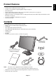
English Product Features • DisplayPort, which supports 10-bit color depth. • 5-setting, easy-to-switch picture mode (see page 11). • Accurate color reproduction for high-end graphic design (see page 11). • Quick warmup time. • Picture-in-picture/picture-by-picture dual-screen mode includes real-time preview (see page 21). • USB hub with two upstream ports (see page 12).
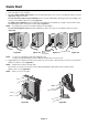
Quick Start To connect the LCD monitor to your system, follow these instructions: 1. Turn off the power to your computer. 2. For a PC or MAC with DVI digital output: Connect the DVI signal cable to the connector of the display card in your system (Figure A.1). Tighten all screws. For a PC with Analog output (only for PA241W): Connect a 15-pin mini D-SUB to DVI-A signal cable (not included) to the connector of the display card in your system (Figure A.2).
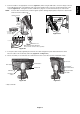
NOTE: Incorrect cable connections may result in irregular operation, damage display quality/components of LCD module and/or shorten the module’s life. 30° Tilt USB downstream A Type Highest Stand Position A Type B Type B Type USB downstream USB upstream1 Figure C.1a USB upstream2 DVI-1 D-SUB*1 DVI-2 DisplayPort DC-OUT* Power cord * NEC optional product attachment. Do not use this connector unless specified. Figure C.1 5.
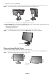
7. Slide down the cable cover (Figure D.1). 8. Connect one end of the power cord to the AC inlet on the back of the monitor and the other end to the power outlet. NOTE: Please refer to Caution section of this manual for proper selection of AC power cord. Figure D.1 9. Turn on the monitor with the front power button (Figure E.1) and the computer. 10. Only for PA241W: No-touch auto adjust automatically adjusts the monitor to optimal settings upon initial setup for most timings.
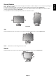
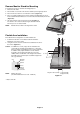
Before rotating, the screen must be raised to the highest level and tilt to avoid knocking the screen on the desk or pinching your fingers. Disconnect all cables. To raise the screen, place hands on each side of the monitor and lift up to the highest position (Figure RL.1). To rotate screen, place hands on each side of the monitor screen and turn clockwise from Landscape to Portrait or counterclockwise from Portrait to Landscape (Figure R.1).
Remove Monitor Stand for Mounting To prepare the monitor for alternate mounting purposes: 1. Disconnect all cables. 2. Place hands on each side of the monitor and lift up to the highest position. 3. Place monitor face down on a non-abrasive surface (Figure S.1). 4. Place one hand around the base and one hand on the Quick Release Lever. Push and hold the Quick Release Lever in the direction indicated by the arrows (Figure S.1). 5. Lift up the stand to unhook it from the monitor (Figure S.1).
OSD (On-Screen Display) control buttons on the front of the monitor function as follows: To access OSD menu, press the MENU button. To change signal input, press the SELECT button. NOTE: OSD must be closed in order to change signal input. 8 7 Landscape 9 1 2 3 4 5 6 Portrait 1 AUTO DIMMING SENSOR Detects the level of ambient lighting allowing the monitor to make adjustments to various settings resulting in a more comfortable viewing experience. Do not cover this sensor.
Brightness/Contrast Controls BRIGHTNESS Adjusts the overall image and background screen brightness. NOTE: The brightness level is adjusted using the backlight output. The display will digitally compensate for low or high brightness levels. If digital compensation occurs, the brightness value on the OSD will change to magenta. NOTE: The optimal display performance will be in the range where the OSD brightness value is black.
Improves focus, clarity and image stability by increasing or decreasing this setting. If the “Auto Adjust function” and the “H.Size” function do not give you a satisfactory picture setting, a fine tuning can be performed using the “Fine” function. For this a Moiré test pattern could be used. If the Fine value is wrongly calibrated, the result would look like the left drawing. The image should be homogeneous. When FINE value is wrong. When FINE value is correct.
Tools PIP MODE Select PIP MODE, OFF/PIP/PICTURE BY PICTURE - ASPECT/PICTURE BY PICTURE - FULL. You can select individual PICTURE MODE in each screen. This display can display 2 inputs at a time. PIP*2 OFF PICTURE BY PICTURE - ASPECT*3 PICTURE BY PICTURE - FULL*3 PICTURE BY PICTURE - ASPECT*3 PICTURE BY PICTURE - FULL*3 IMAGE ROTATION: ON OFF*1 PIP*1 PIP INPUT Selects the PIP input signal. PIP LEFT/RIGHT Controls the horizontal position of the Picture in Picture window in PIP mode.
The Intelligent Power Manager allows the monitor to enter into a power saving mode after a period of inactivity. The OFF MODE has three settings. OFF: Monitor does not go into power save mode when the input signal is lost. STANDARD: Monitor enters power save mode automatically when the input signal is lost. OPTION: Monitor enters power save mode automatically when the amount of surrounding light goes below the level that is determined by the user. The level can be adjusted in Tag 7 of the Advanced OSD menu.
FACTORY PRESET Selecting Factory Preset allows you to reset all OSD control settings (BRIGHTNESS, CONTRAST*1, ECOMODE, BLACK, IMAGE CONTROL, COLOR CONTROL SYSTEM, SHARPNESS, PIP MODE, PIP INPUT, PIP LEFT/RIGHT, PIP DOWN/UP, PIP SIZE, USB SELECTION, EDID EXTENSION, OFF TIMER, OFF MODE, OSD LEFT/RIGHT, OSD UP/DOWN, OSD TURN OFF, OSD TRANSPARENCY) back to the factory settings. Individual settings can be reset by highlighting the control to be reset and pressing the RESET button.
Choose the Picture mode that is most suitable for the type of content that is shown. There are several types of mode (sRGB, Adobe®RGB, DCI, REC-Bt709, HIGH BRIGHT, FULL, DICOM, PROGRAMMABLE). • Each PICTURE MODE includes BRIGHTNESS, WHITE, Color Gamut, GAMMA, BLACK, UNIFORMITY, COLOR VISION EMU, METAMERISM, RESPONSE IMPROVE settings. You can change these settings in Tag1 advanced menu.
Advanced OSD If you need detailed information about the controls, please use the advanced menu. There are 2 ways to access the advanced menu. Way 1: • Press the Menu button to access OSD menu. Use the front buttons to move the cursor to the ADVANCED SETTING in Color control systems. Press INPUT button to appear advanced menu. • Press the EXIT button. Way 2: • Turn off the monitor.
Allows you to manually select the brightness level of grayscale. There are five selections: sRGB, L Star, DICOM, PROGRAMMABLE and CUSTOM. We recommend to show grayscale image data on screen. sRGB: GAMMA setting for sRGB. L Star: GAMMA for Lab color space. DICOM: DICOM GSDF (Grayscale Standard Display Function) is typically used for medical imaging. PROGRAMMABLE: The brightness of grayscale can be changed to your preference by downloading the application software.
Tag2 Tag3 SHARPNESS This is a digital capability for keeping a crisp image at all signal timings. It continuously adjusts to maintain as distinct or as soft image as you prefer, and is set independently according to different timings. Press “Left” or “Right” to adjust. RESPONSE IMPROVE Turns the Response Improve function on or off. Response Improve may reduce blurring that occurs in some moving images. ECO MODE Decreases the amount of power consumed by reducing the brightness level. OFF: No function.
AUTO ADJUST*2 Automatically adjusts the Image Position and H.Size settings and Fine settings. Press “SELECT” to activate Auto Adjustment. Please use test pattern, which is included in the enclosed CD-ROM. SIGNAL ADJUST Determines when the auto adjustment is activated automatically. The choices are “SIMPLE” and “FULL”. Press “Left” or “Right” to select.
Tag6 V.RESOLUTION Adjusts the vertical size by increasing or decreasing the setting. Press “Right” button to expand the height of the image on the screen. Press “Left” button to narrow the height of the image on the screen. EXPANSION Sets the zoom method. FULL: The image is expanded to full screen, regardless of the resolution. ASPECT: The image is expanded without changing the aspect ratio. OFF: The image is not expanded.
This control completely locks out access to all OSD control functions. When attempting to activate OSD controls while in the Lock Out mode, a screen will appear indicating the OSD controls are locked out. There are three types of OSD LOCK OUT: OSD LOCK OUT with no control: To activate the OSD Lock Out function, press SELECT, then “Right” button and hold down simultaneously. To deactivate the OSD Lock Out, press SELECT, then “Right” button and hold down simultaneously while in the OSD menu.
DDC/CI DDC/CI ENABLE/DISABLE: Turns on or off the two way communication and control with connected PC by video cable. NOTE: Set DDC/CI to ENABLE when using hardware calibration software like MultiProfiler over DisplayPort, DVI or VGA. SCREEN SAVER Use the SCREEN SAVER to reduce the risk of image persistence. MOTION (Default OFF): Screen image moves periodically in 4 directions in order to reduce the risk of image retention.
TagC CARBON SAVING Displays the estimated carbon savings information in kg. COST Displays the electricity cost savings in balance. CARBON CONVERT SETTING Adjusts the carbon footprint factor in the carbon saving calculation. This initial setting is based on the OECD (2008 Edition). CURRENCY SETTING*2 Displays electricity pricing (available in 6 currency units). CURRENCY CONVERT SETTING Adjusts electricity prices-electric energy equivalent in the electrical rate saving calculation.
Recommended use Safety Precautions and Maintenance FOR OPTIMUM PERFORMANCE, PLEASE NOTE THE FOLLOWING WHEN SETTING UP AND USING THE LCD COLOR MONITOR: • DO NOT OPEN THE MONITOR. There are no user serviceable parts inside and opening or removing covers may expose you to dangerous shock hazards or other risks. Refer all servicing to qualified service personnel. • Do not spill any liquids into the cabinet or use your monitor near water.
• For optimum performance, allow 20 minutes for the display to warm up. • Adjust the monitor height so that the top of the screen is at or slightly below eye level. Your eyes should look slightly downward when viewing the middle of the screen. • Position your monitor no closer than 40 cm (15.75 inches) and no further away than 70 cm (27.56 inches) from your eyes. The optimal distance is 50 cm (19.69 inches). • Rest your eyes periodically by focusing on an object at least 20 feet away. Blink often.
Specifications - PA241W Monitor Specifications MultiSync PA241W Notes LCD Module 61.1 cm/24.1 inches 61.1 cm/24.1 inches 1920 x 1200 Active matrix; thin film transistor (TFT) liquid crystal display (LCD); 0.270 mm dot pitch; 360 cd/m2 white luminence; 1000:1 contrast ratio, typical. DisplayPort Connector: Digital RGB DisplayPort Complies with Standard V1.1a, applicable to HDCP DVI-D 24pin: Digital RGB DVI (HDCP) Analog RGB Sync 0.7 Vp-p/75 ohm Separate sync.
Monitor Specifications MultiSync PA271W Notes LCD Module 68.5 cm/27.0 inches 68.5 cm/27.0 inches 2560 x 1440 Active matrix; thin film transistor (TFT) liquid crystal display (LCD); 0.225 mm dot pitch; 300 cd/m2 white luminence; 1000:1 contrast ratio, typical. DisplayPort Connector: Digital RGB DisplayPort Complies with Standard V1.
Features DisplayPort: DisplayPort is designed to be the future-ready, scalable solution for high performance digital display connectivity. It enables the highest resolutions, the fastest refresh rates and deepest color depths over standard cables. DFP (Digital Flat Panel): An all-digital interface for flat panel monitors which is signal compatible with DVI.
No picture • The signal cable should be completely connected to the display card/computer. • The display card should be completely seated in its slot. • The monitor does not support DisplayPort converter signal. • Front Power Switch and computer power switch should be in the ON position. • Check to make sure that a supported mode has been selected on the display card or system being used. (Please consult display card or system manual to change graphics mode.
No Video • If no video is present on the screen, turn the Power button off and on again. • Make certain the computer is not in a power-saving mode (touch the keyboard or mouse). • Some video cards do not output video signal when monitor is turned OFF/ON or disconnect/connect from the AC power cord under low resolution with DisplayPort.
The brightness of the LCD screen can be set to increase or decrease depending on the amount of ambient light within the room. If the room is bright, the monitor becomes correspondingly bright. If the room is dim, then the monitor will dim accordingly. The purpose of this function is to make the viewing experience more comfortable to the eye in a variety of lighting conditions. The Auto Brightness function is set to OFF by default.
TCO’03 (for MultiSync PA271W) Congratulations! The display you have just purchased carries the TCO’03 Displays label. This means that your display is designed, manufactured and tested according to some of the strictest quality and environmental requirements in the world. This makes for a high performance product, designed with the user in focus that also minimizes the impact on our natural environment.
Congratulations! This display is designed for both you and the planet! The display you have just purchased carries the TCO CertiÞed label. This ensures that your display is designed, manufactured and tested according to some of the strictest quality and environmental requirements in the world. This makes for a high performance product, designed with the user in focus that also minimizes the impact on the climate and our natural environment.
Manufacturer’s Recycling and Energy Information NEC DISPLAY SOLUTIONS is strongly committed to environmental protection and sees recycling as one of the company’s top priorities in trying to minimize the burden placed on the environment. We are engaged in developing environmentallyfriendly products, and always strive to help define and comply with the latest independent standards from agencies such as ISO (International Organisation for Standardization) and TCO (Swedish Trades Union).