User's Manual MultiSync LCD1770VX
Index Warning .................................................................................................................... 1 Contents ................................................................................................................. 2 Display Setup ......................................................................................................... 3 Mounting .................................................................................................................
WARNING TO PREVENT FIRE OR SHOCK HAZARDS, DO NOT EXPOSE THIS UNIT TO RAIN OR MOISTURE. ALSO, DO NOT USE THIS UNIT'S POLARIZED PLUG WITH AN EXTENSION CORD RECEPTACLE OR OTHER OUTLETS UNLESS THE PRONGS CAN BE FULLY INSERTED. REFRAIN FROM OPENING THE CABINET AS THERE ARE HIGH VOLTAGE COMPONENTS INSIDE. REFER SERVICING TO QUALIFIED SERVICE PERSONNEL. CAUTION CAUTION: TO REDUCE THE RISK OF ELECTRIC SHOCK, MAKE SURE POWER CORD IS UNPLUGGED FROM WALL SOCKET.
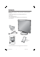
Contents Your new NEC MultiSync® LCD monitor box* should contain the following: • MultiSync LCD1770VX monitor with height adjustable stand • Power Cord • Cable Management Cover • Video Signal Cable (mini D-SUB 15 pin to mini D-SUB 15 pin) • User’s Manual Power Cord Mini D-SUB Cable Cable Management Cover User's Manual MultiSync LCD1770VX User’s Manual * Remember to save your original box and packing material to transport or ship the monitor. 2 LCD1770VX042205.
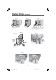
Display Setup To attach the MultiSync® LCD monitor to your system, follow these instructions: 1. Turn off the power to your computer. 2. For the PC or MAC with DVI digital output : Connect the DVI signal cable to the connector of the display card in your system (Figure 1). Tighten all screws. For the PC with Analog output: Connect the 15-pin mini D-SUB signal cable to the connector of the display card in your system (Figure 2). Tighten all screws.
Display Setup –continued Figure 1 Figure 2 DVI Signal Cable Figure 3 Macintosh Cable Adapter (not included) Note: Some Macintosh systems do not require a Macintosh Cable Adapter Figure 4 30° Tilt Figure 5 DVI Cable (Top) Power Cable (Bottom) Highest Stand Position DVI Cable Figure 6 DVI Cable Power Cable Ridge 4 LCD1770VX042205.
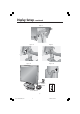
Display Setup –continued Figure 7 D-Sub Cable Figure 8 Figure 9 Figure 11 Figure 10 Vacation Switch Power Button OFF Position ON Position 5 LCD1770VX042205.
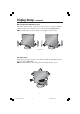
Display Setup –continued Raise and Lower Monitor Screen The monitor may be raised or lowered. To raise or lower screen, place hands on each side of the monitor and lift or lower to the desired height (Figure RL.1). NOTE: Handle with care when raising or lowering the monitor screen. Figure RL.1 Tilt and Swivel Grasp both sides of the monitor screen with your hands and adjust the tilt and swivel as desired (Figure TS.1). NOTE: Handle with care when tilting and swiveling the monitor screen. Figure TS.
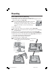
Mounting Remove Monitor Stand for Mounting To prepare the monitor for an alternate mounting method: 1. Place hands on each side of the monitor and lift up to the highest position. Remove the cable cover (Figure M.1). NOTE: If you have difficulty removing the cable cover, please push the the notch at the bottom of the cover up (towards the top of the monitor)in order to unhook the cover from the stand, as shown in the following figure. Figure 2. Disconnect all cables. 3.
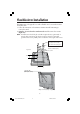
Flexible Arm Installation This LCD monitor is designed for use with a flexible arm. To mount the monitor to a flexible arm: 1. Follow the instructions on how Remove Monitor Stand for Mounting to remove the stand. 2. Using the 4 screws from the stand removal attach the arm to the monitor (Figure F.1). NOTE: The LCD monitor should only be used with an approved arm (e.g. GS mark).
Controls OSM® (On-Screen Manager) control buttons on the front of the monitor function as follows: To access OSM menu, press any of the control buttons (MENU/EXIT, Left, Right, Down, Up). To change signal input, press the SELECT button. NOTE: OSM must be closed in order to change signal input. Button Menu MENU/EXIT Exits the OSM controls. Exits to the OSM main menu. Left/Right Moves the highlighted area left/right to select control menus. Moves the bar left/right to increase or decrease the adjustment.
Controls –continued AccuColor® Control Systems AccuColor® Control Systems: Six color presets select the desired color setting (sRGB and NATIVE color presets are standard and cannot be changed). R,G,B: Increases or decreases Red, Green or Blue color depending upon which is selected. The change in color will appear on screen and the adjustment (increase or decrease) will be shown by the bars. NATIVE: Original color presented by the LCD panel that is unadjustable.
RESOLUTION NOTIFIER: If this option is ON, a message will appear on the screen after 30 seconds notifying the user that the optimal resolution is not being used. The optimal resolution is 1280 x 1024. Information The Information menu indicates the current input, display resolution, horizontal and vertical frequency, and polarity settings of the monitor. The model and serial numbers of your monitor are also indicated. OSM® Warning: OSM Warning menus disappear with Exit button.
Recommended Use Safety Precautions and Maintenance FOR OPTIMUM PERFORMANCE, PLEASE NOTE THE FOLLOWING WHEN SETTING UP AND USING THE MULTISYNC® LCD COLOR MONITOR: • DO NOT OPEN THE MONITOR. There are no user serviceable parts inside and opening or removing covers may expose you to dangerous shock hazards or other risks. Refer all servicing to qualified service personnel. • Do not spill any liquids into the cabinet or use your monitor near water.
Recommended Use –continued CORRECT PLACEMENT AND ADJUSTMENT OF THE MONITOR CAN REDUCE EYE, SHOULDER AND NECK FATIGUE. CHECK THE FOLLOWING WHEN YOU POSITION THE MONITOR: • For optimum performance, allow 20 minutes for warm-up. • Adjust the monitor height so that the top of the screen is at or slightly below eye level. Your eyes should look slightly downward when viewing the middle of the screen. • Position your monitor no closer than 16 inches and no further away than 28 inches from your eyes.
Specifications Monitor Specifications MultiSync® LCD1770VX Monitor LCD Module Diagonal : Viewable Image Size : Native Resolution (Pixel Count) : 17.0 inch 17.0 inch 1280 x1024 Active matrix; thin film transistor (TFT) liquid crystal display (LCD); 0.264 mm dot pitch; 250cd/m2 white luminence; 500:1 contrast ratio, typical Input Signal Video : Sync : ANALOG 0.7 Vp-p/75 Ohms Separate sync. TTL Level Horizontal sync. Positive/Negative Vertical sync.
Features Thin-frame design creates more desktop space for you to work and play, while the flat screen’s crisp, bright images and crystal-clear text deliver a comfortable viewing experience. No Touch Auto Adjust™ automatically adjusts your optimal image settings upon initial power-on. AccuColor® Control System allows you to change between six color settings on your display to match your personal preference. Redesigned OSM® controls allow you to quickly and easily adjust all elements of your screen image.
Troubleshooting No • • • • • picture The signal cable should be completely connected to the display card/computer. The display card should be completely seated in its slot. Make sure the Vacation Switch is in the ON position. Front Power Switch and computer power switch should be in the ON position. Check to make sure that a supported mode has been selected on the display card or system being used. (Please consult display card or system manual to change graphics mode.
References NEC Monitor Customer Service & Support Customer Service and Technical Support: (800) 632-4662 Fax: (800) 695-3044 Parts and Accessories/Macintosh Cable Adapter: (800) 632-4662 Warranty Information: www.necdisplay.com Online Technical Support www.necdisplay.com Sales and Product Information Sales Information Line: (888) 632-6487 Canadian Customers: (866) 771-0266, Ext#: 4037 Government Sales: (800) 284-6320 Government Sales email: gov@necdisplay.
Limited Warranty NEC Display Solutions of America, Inc. (hereinafter “NEC DISPLAY SOLUTIONS”) warrants this Product to be free from defects in material and workmanship and, subject to the conditions set forth below, agrees to repair or replace (at NEC DISPLAY SOLUTIONS’ sole option) any part of the enclosed unit which proves defective for a period of three (3) years from the date of first consumer purchase. Spare parts are warranted for ninety (90) days.
TCO’99 –Black Models Congratulations! You have just purchased a TCO’99 approved and labelled product! Your choice has provided you with a product developed for professional use. Your purchase has also contributed to reducing the burden on the environment and also to the further development of environmentally adapted electronics products.
TCO’99 –continued accumulative* processes. Flame retardants have been found in human blood and researchers fear that disturbances in foetus development may occur. TCO’99 demand requires that plastic components weighing more than 25 grams must not contain flame retardants with organically bound chlorine and bromine. Flame retardants are allowed in the printed circuit boards since no substitutes are available. Lead** Lead can be found in picture tubes, display screens, solders and capacitors.
TCO’03 –White Models Congratulations! The display you have just purchased carries the TCO’03 Displays label. This means that your display is designed, manufactured and tested according to some of the strictest quality and environmental requirements in the world. This makes for a high performance product, designed with the user in focus that also minimizes the impact on our natural environment.
Manufacturer’s Recycling and Energy Information NEC DISPLAY SOLUTIONS is strongly committed to environmental protection and sees recycling as one of the company’s top priorities in trying to minimize the burden placed on the environment. We are engaged in developing environmentally-friendly products, and always strive to help define and comply with the latest independent standards from agencies such as ISO (International Organization for Standardization) and TCO (Swedish Trades Union).
Declaration of the Manufacturer We hereby certify that the color monitor MultiSync® LCD1770VXTM (L174F) is in compliance with Council Directive 73/23/EEC: – EN 60950-1 Council Directive 89/336/EEC: – EN 55022 – EN 61000-3-2 – EN 61000-3-3 – EN 55024 and marked with NEC Display Solutions, Ltd. 4-13-23, Shibaura, Minato-Ku Tokyo 108-0023, Japan 23 LCD1770VX042205.
AVERTISSEMENT AFIN D’ÉVITER TOUT RISQUE D’INCENDIE OU D’ÉLECTROCUTION, NE PAS EXPOSER CET APPAREIL À LA PLUIE OU À L’HUMIDITÉ. NE PAS UTILISER LA FICHE D’ALIMENTATION POLARISÉE AVEC UNE PRISE DE CORDON DE RALLONGE OU AUTRE PRISE SAUF SI LES BROCHES PEUVENT ÊTRE ENTIÈREMENT INTRODUITES. NE PAS OUVRIR LE BOÎTIER, LEQUEL CONTIENT DES COMPOSANTS À HAUTE TENSION. CONFIER TOUS TRAVAUX À DU PERSONNEL TECHNIQUE QUALIFIÉ.
Contenu La boîte* de votre nouveau moniteur NEC MultiSync® contient : • Moniteur MultiSync LCD1770VX avec sa base ajustable en hauteur • Cordon d'alimentation • Un cache-câbles • Câble pour le signal vidéo (Mini D-SUB mâle 15 broches vers D-SUB) • Manuel de l’utilisateur Cordon d'alimentation Câble pour le signal vidéo Un cache-câbles User's Manual MultiSync LCD1770VX Manuel de l’utilisateur * Ne pas oublier de conserver la boîte et le matériel d'emballage d'origine pour transporter ou expédier le monit
Configuration de I’affichage Suivez ces instructions pour fixer le moniteur ACL MultiSync® à votre système: 1. Mettez votre ordinateur hors tension. 2. Pour le MAC ou le PC avec sortie numérique DVI Branchez le câble de signal DVI au connecteur de la carte d’écran de votre système (Figure 1). Serrez toutes les vis avant de continuer. Pour le PC avec sortie analogique: Branchez le mini D-SUB à 15 broches du câble de signal au connecteur de la carte d’écran de votre système (Figure 2). Serrez toutes les vis.
Configuration de I’affichage (suite) Figure 1 Figure 2 DVI Signal cable Figure 3 Adaptateur de câble (non fourni) Remarque: Certains systémes Macintosh ne nécessitent pas un adaptateur de câble Macintosh. Figure 4 Inclinaison de 30° Figure 5 Câble DVI (haut) Position du support la plus élevée Cordon d'alimentation (milieu) Câble DVI Figure 6 Cordon d'alimentation Câble DVI Ridge 27 LCD1770VX042205.
Configuration de I’affichage (suite) Figure 7 Câble D-Sub Figure 8 Figure 9 Figure 11 Figure 10 Interrupteur de vacances Bouton d’alimentation Position OFF (Arrêt) Position On (Marche) 28 LCD1770VX042205.
Configuration de I’affichage (suite) Levez et baissez l’écran du moniteur Le moniteur peut être élevé ou abaissé. Pour élever ou abaisser l’écran, placez les mains de chaque côté du moniteur et situez-le à la hauteur de votre choix (Figure RL.1). REMARQUE: Manipule sur soin quand augmentant ou l’écran diminuant écran. Figure RL.1 Inclinaison et pivotement Maintenez les deux côtés du moniteur, puis ajustez l’inclinaison et l’orientation à votre convenance (Figure TS.1).
Montage Enlevez le support du moniteur pour le montage Pour préparer le moniteur à des fins de montage différents : 1. Placez les mains de chaque côté du moniteur en le soulevant dans sa position la plus haute. Enlevez la gaine de câble (Figure M.1). REMARQUE: Si vous avez la difficulté enlever la couverture de câble, soulevez svp la l'entaille au fond de la couverture (vers le dessus de l'ordre de monitor)in pour décrocher la couverture du stand, comme représenté sur la figure suivante. 2.
Installation du bras flexible Installation du bras flexible Ce moniteur ACL est conçu pour une utilisation avec un bras flexible. Pour fixer le moniteur à un bras flexible: 1. Suivez les instructions sur comment enlever le support de moniteur pour le montage afin d’enlever le support. 2. Utilisez les 4 vis provenant du retrait du support pour fixer le bras au moniteur (Figure F.1). REMARQUE: Le moniteur ACL ne doit être utilisé qu’avec un bras homologué (par ex. de marque GS).
Commandes Les boutons de réglage OSM® situés sur l’avant du moniteur fournissent les fonctions suivantes : Pour accéder au menu OSM, appuyez sur une des touches de commande (MENU/EXIT, Left, Right, Down, Up). Pour changer l’entrée du signal, appuyez sur le bouton SELECT. REMARQUE: Le menu OSM doit être fermé pour pouvoir modifier le signal d’entrée. Bouton Menu principal MENU/EXIT Quitte les commandes OSM. Revient au menu principal OSM.
Commandes (suite) Système de contrôle des couleurs AccuColor® Six colore prérégle sélectionner la désiré couleur mettant (sRGB et NATIVE couleur prérégle sommes standards et cannot être transformé).R, V, B: Augmente ou diminue le niveau des couleurs rouge, vert ou bleu, suivant celui qui a été sélectionné. Le changement de couleur apparraît à l’écran et le sens (augmentation ou diminution) est indiqué par les barres de couleur. Native: Originale couleur nrésenta par le LCD panel qu’est unadjustable.
VERROUILLAGE OSM : Cette commande permet de verrouiller l’accès à toutes les fonctions de commandes OSM à l’exception de la luminosité et du contraste. Lorsque vous tentez d’activer les commandes OSM en mode de Verrouillage, un écran apparaîtra indiquant que les commandes OSM sont verrouillées. Pour activer la fonction Verrouillage OSM, appuyez sur SELECT, puis sur la touche de commande de droite en les maintenant enfoncées simultanément.
Usage recommandé Consignes de sécurité et d’entretien POUR UN FONCTIONNEMENT OPTIMAL, PRIÈRE DE NOTER CE QUI SUIT POUR LE RÉGLAGE ET L'UTILISATION DU MONITEUR COULEUR MULTISYNC® LCD : • NE PAS OUVRIR LE MONITEUR. Aucune pièce intérieure ne nécessite l'intervention de l'utilisateur, et l'ouverture ou la dépose des couvercles peut entraîner des risques de décharges électriques dangereuses ou d'autres risques. Confier tous travaux à du personnel technique qualifié.
Usage recommandé (suite) • • • • • • • • • • LA MODIFICATION DE LA POSITION ET DU RÉGLAGE DU MONITEUR PEUT RÉDUIRE LA FATIGUE DES YEUX, DES ÉPAULES ET DE LA NUQUE. OBSERVER LES DIRECTIVES CI-APRÈS LORS DU POSITIONNEMENT DU MONITEUR : Pour une performance optimale, laissez le moniteur se réchauffer pendant 20 minutes. Régler la hauteur du moniteur de sorte que le dessus de l'écran soit au niveau ou légèrement en-dessous du niveau des yeux.
Fiche technique Caractér. techn. du moniteur Moniteur MultiSync® LCD1770VX™ Module LCD 17,0 po 17,0 po 1280 x 1024 Matrice active; transistor à film fin (TFT); affichage à cristaux liquides (LCD); pas 0,264 mm; luminance blanche 250cd/m2; taux de contraste caractéristique 500:1. ANALOGIQUE 0,7 Vp-p/75 Ohms Synchro séparée niveau TTL. Positif/négative sync. horizontale Positif/négative sync. verticale Entrée numérique: DVI-D 16.194.277 Dépend de la carte vidéo et synchronisation utilisée.
Fonctions Le design à mince encadrement vous permet de libérer davantage d’espace pour travailler et jouer, alors que les images brillantes et éclatantes et le texte aussi clair que du cristal de l’éran plat vous offrent une expérience de visionnement incomparable. La fonction avancée Réglage automatique sans touche offre des réglages d’image optimaux dès la mise sous tension initiale.
Dépannage Pas • • • • d'image Le câble vidéo doit être bien connecté à la carte d'affichage et à l’ordinateur. La carte d'affichage doit être insérée à fond dans son logement. Vérifiez que l’interrupteur de vacances soit sur la position MARCHE. Les interrupteurs d’alimentation du moniteur à l’avantet de l’ordinateur doivent être sur la position MARCHE.
Références Service à la clientèle et assistance technique du moniteur NEC Service à la clientèle et assistance technique: (800) 632-4662 Télécopieur: (800) 695-3044 Pièces et accessoires/adaptateur de câble Macintosh: (800) 632-4662 Information sur la garantie: www.necdisplay.com Assistance technique en ligne www.necdisplay.
Garantie limitée NEC Display Solutions of America, Inc. (ci-après «NEC DISPLAY SOLUTIONS») garantit que ce produit est exempt de vice de fabrication et de main-d’oeuvre et, selon les conditions énoncées ci-dessous, accepte de réparer ou remplacer, à sa discrétion, toute pièce de l’appareil concerné qui s’avérerait défectueuse et ce, pendant une période de trois (3) ans à partir de la date d’achat initial. Les pièces de rechange sont garanties pendant quatre-vingt dix (90) jours.
TCO’99 – le modèle noir (C’est une traduction de portion Anglaise de TCO’99.) Félicitations! Vous avez acheté un produit qui répond à la directive TCO’99. En choisissant ce produit conçu pour une utilisation professionnelle, vous contribuez aussi à la réduction des effets nuisibles sur l’environnement et aussi au développement continu de produits électroniques respectueux de l’environnement.
TCO’99 (suite) organiquement liés. Les retardateurs de flame sont autorisés dans les cartes à circuits imprimés étant donné qu’aucun substitut n’est encore disponible. Plomb** Le plomb peut être présent dans les tubes cathodiques, les écrans, les soudures et les condensateurs. Le plomb s’attaque au système nerveux et, à doses élevées, entraîne l’intoxication par le plomb. La directive TCO’99 permet l’inclusion du plomb était donné qu’aucun remplacement n’ait encore été mis au point.
TCO’03 – le modèle blanc Félicitations ! L’écran que vous venez d'acheter porte l’étiquette « Displays TCO’03 ». Ceci signifie que votre écran a été conçu, fabriqué, et vérifié selon certaines des directives relatives à la qualité et aux exigences environnementales les plus strictes au monde. Cela permet à un produit de haute performance, conçu avec l’utilisateur comme priorité, de réduire son impact sur notre environnement naturel.
Informations du fabricant relatives au recylage et aux économies d’énergie NEC DISPLAY SOLUTIONS est extrêmement résolu à protéger l’environnement et considère le recyclage comme l’une des principales priorités de l’entreprise en essayant de minimiser les répercussions sur l’environnement.
Déclaration du fabricant Nous certifions par la présente que les moniteurs MultiSync® LCD1770VXTM (L174F) conformes à la directive 73/23/EEC du Counseil: – EN 60950-1 la directive 89/336/EEC du Counseil: – EN 55022 – EN 61000-3-2 – EN 61000-3-3 – EN 55024 et porte le sigle NEC Display Solutions, Ltd. 4-13-23, Shibaura, Minato-Ku Tokyo 108-0023, Japan 46 LCD1770VX042205.
LCD1770VX042205.
LCD1770VX042205.
Série LCD NEC AVIS DE PROPRIÉTÉ EXCLUSIVE ET DE DÉGAGEMENT DE RESPONSABILITÉ Les informations contenues dans ce document, y compris tous les designs et matériel s'y rapportant, sont la propriété de NEC Display Solutions of America, Inc. et/ou ses concédants. NEC Display Solutions of America, Inc.
NEC LCD Series PROPRIETARY NOTICE AND LIABILITY DISCLAIMER The information disclosed in this document, including all designs and related materials, is the valuable property of NEC Display Solutions of America, Inc. and/or its licensors, as appropriate, reserve all patent, copyright and other proprietary rights to this document, including all design, manufacturing, reproduction, use and sales rights thereto, except to the extent said rights are expressly granted to others.