VERSA M350/P550 Disassembly Manual
Table of contents Overview.................................................................................................................................................................3 Technician Notes....................................................................................................................................................3 Disassembly Instructions.....................................................................................................................................
Overview This document contains step-by-steps disassembly instructions for the VERSA M350/P550 chassis. The instructions are illustrated where necessary with images of the part that is being removed or disassembled. Furthermore, the screws that are removed are shown next to the image of the parts themselves. NEC reserves the right to make changes to the VERSA M350/P550 chassis without notice. Technician Notes Only technicians authorized by NEC Personal Products LTD. should attempt to repair this equipment.
Hazardous Voltage There is hazardous voltage present inside the computer when it is connect to an AC supply, even when the computer’s power switch is off. Exposure to hazardous voltage could cause personal injury. To avoid risk of injury, contact an Authorized Service Provider for proper (UN)installation of optional hardware devices. Avoid Electrostatic Discharge Electrostatic electricity can easily damage circuit cards and integrated circuits (ICs).
NEC VERSA M350/P550 Disassembly Manual Page 5
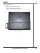
Removing the Battery Perform the following steps to remove the battery: 1. Make sure to power off the VERSA M350/P550 2. Turn the unit upside down. 3. Unlock the battery and slide it out of its place as the arrow shows in Fig. 1 Fig.
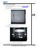
Removing the Memory Module To remove the Memory Module, first remove the battery (see Removing the Battery), then perform the following steps: 1. Release the one screw retaining the memory module cover. M2x4 Sliver Fig. 2 Removing the screw retaining the memory module slot cover 2. Unclip the memory module as shown in Fig. 3 Fig. 3 Removing the memory module 3. Remove the memory module from its slot and put it aside.
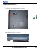
Removing the Hard Disk Drive To remove the hard disk drive, first remove the battery (see Removing the Battery), then perform the following steps: 1. Remove the screws as shown in Fig. 4 M3x7 Copper Fig. 4 Removing the Hard disk drive cover 2. Release the screws that secure HDD module as shown in Fig. 5 and carefully pull the HDD module out from the base unit. M3x7 Copper Fig.
Removing the Optical Disk Drive To remove the ODD, first remove the battery (see Removing the Battery) then perform the following steps: 1. Remove the screws retaining the optical drive as shown in Fig. 6 M2.5x9 Copper Fig. 6 Releasing the optical drive 2. Eject the optical drive using pin as shown in Fig. 7 Fig.
3. Flip over the unit, and pull the ODD module out from the base unit as shown in Fig. 8 Fig. 8 Pulling the optical drive out from the base unit Removing the Keyboard To remove the Keyboard, first remove the battery (see Removing the Battery), then perform the following steps: 1. Release the keyboard cover from the rear of the system as shown in Fig. 9 Fig.
2. Lift up the keyboard cover carefully as shown in Fig. 10 Fig. 10 Lifting up the Keyboard Cover 3. Lift up the keyboard and disconnect it from the system as shown in Fig. 11 Fig.
Removing the Wireless LAN Module To remove the Wireless LAN Module first remove the battery (see Removing the Battery) and remove the Keyboard (see Removing the Keyboard) then perform the following steps: 1. Remove the screws retaining the Heat Plate as shown in Fig. 12 and lift it up carefully M2.5 x 7 Sliver Fig. 12 Removing the screws retaining the Heat Plate 2. Disconnect wireless antenna connection and then release it from mini PCI slot as shown in Fig. 13 Fig.
Removing the CPU (For K2S) To remove the CPU first remove the battery (see Removing the Battery) and remove the Keyboard (see Removing the Keyboard) then perform the following steps: 3. Remove the screws retaining the Heat Plate as shown in Fig. 14 M2.5 x 7 Sliver Fig. 14 Removing the screws retaining Heat Plate 4. Disconnect Fan connection and remove the CPU Heat sink screws around CPU socket in descending order (6Æ5Æ4Æ3Æ2Æ1), then lift up the CPU heat sink and CPU Fan separately. M2.5 x 6 Sliver Fig.
Note: Beware of screws use on the CPU heat sink! Make sure to use the screw size M2.5x7, otherwise it might cause damage to the CPU die. Secure the screw around the CPU socket first before other screws. 5. Use Flat screwdriver to unlock the CPU from the CPU socket and lift up the CPU carefully. Fig. 16 Unlocking the CPU Removing the CPU (For K2ST) To remove the CPU first remove the battery (see Removing the Battery) and remove the Keyboard (see Removing the Keyboard) then perform the following steps: 1.
2. Remove the CPU Fan screws and disconnect CPU Fan as shown in Fig. 18 M2.5 x 6 Sliver Fig. 18 CPU Fan 3. Unscrew the GPU heat sink. M2x4 Sliver Fig.
4. Disconnect Fan connection and remove the CPU Heat sink screws around CPU socket in descending order (3Æ2Æ1), then lift up the CPU heat sink. M2.5 x 7 Sliver Fig. 20 CPU Heat Sink Note: Beware of screws use on the CPU heat sink! Make sure to use the screw size M2.5x7, otherwise it might cause damage to the CPU die. Secure the screw around the CPU socket first before other screws. 5. Use Flat screwdriver to unlock the CPU from the CPU socket and lift up the CPU carefully. Fig.
Removing the LCD Module To remove the LCD Module first remove the battery (see Removing the Battery) and remove the Keyboard (see Removing the Keyboard) then perform the following steps: 1. Remove the screws retaining the Heat Plate as shown in Fig. 22 M2.5 x 7 Sliver Fig. 22 Removing the screws retaining the Heat Plate 2. Release the LCD cable connector. Fig.
3. Disconnect Wireless module antenna connector. Fig. 24 Disconnection Wireless Module antenna connector 4. Flip over the base unit and release the screws retaining the LCD Module. M2.5x9 Copper Fig. 25 Removing the screws retaining the LCD Module 5. Release the screws on the system rear side as shown in Fig. 26 M2.5x9 Copper Fig. 26 Removing the screws retaining the LCD Module 6. Carefully lift up the LCD Module.
Removing the LCD Panel To remove the LCD panel, first remove the LCD module (see Removing the LCD Module), then perform the following steps: 1. Use a pin to remove the rubber cover on the LCD module as shown in Fig. 27 2. Remove all screws as shown in Fig. 27 and carefully remove the LCD cover. M2.5X7 Copper Fig. 27 Removing the rubber covers & screws on the LCD Module 3. Removing LCD Bezel as shown in Fig. 28 Fig.
4. Release the inverter board by remove the screw and disconnect all connectors as shown in Fig. 29 M2x3 Copper Fig. 29 Removing the Inverter Board 5. Carefully lift up the LCD panel. 6. Remove the screws at both sides of the LCD panel in order to release the LCD hinges as shown in Fig. 30 M2x3 Copper Fig. 30 Removing the LCD Panel hinges Note: Beware when assembly LCD Bezel. You need to follow below instruction to ensure it properly close at both left and right side of the Bezel. 1.
Removing the Top Cover To remove the Top Cover , first remove the battery (see Removing the Battery), remove the HDD (see Removing the Hard Disk Drive), remove the Optical Disk Drive (see Removing the Optical Disk Drive), remove the Keyboard (see Removing the Keyboard) and remove the LCD Module (see Removing the LCD Module) then perform the following steps: 1. Remove all screws on the bottom of the base unit as shown in Fig. 31 A=M2x4 Sliver B=M2.5x9 Copper Fig.
2. Release all screws on the top cover and disconnect touch pad cable as shown in Fig. 32 M2.5x9 Copper Fig. 32 Top Cover screws 3. Carefully lift up the Top Cover.
Removing the Touch Pad To remove the touch pad, first remove the top cover (see Removing the Top Cover), then perform the following steps: 1. Unscrew the screws on the Top Cover as shown in Fig. 33 M2x3 Copper Fig. 33 Touch Pad 2. Carefully separate the Touch Pad module from Top cover.
Removing the MDC Modem To remove the MDC Modem, first remove the top cover (see Removing the Top Cover), then perform the following steps: 1. Disconnect cable and release screws on MCD Modem as shown in Fig. 34 M2.5 x 7 Sliver Fig. 34 MDC Modem 2. Lift up the MDC modem and put it aside. Removing the Bluetooth Module To remove the Bluetooth Module, first remove the top cover (see Removing the Top Cover), then perform the following steps: 1. Disconnect cable on main board as shown in Fig. 35 Fig.
Removing the Main Board To remove the Main Board, first remove the Top Cover (see Removing Top Cover) then perform the following steps: 1. Remove the Hex screws from the VGA Port as shown in Fig. 36 M2.5x10 Sliver Fig. 36 VGA Port 2. Unscrew those screws on HDD holder as shown in Fig. 37 and separate it carefully from Main Board. M2.5 x 7 Sliver Fig.
3. Disconnect Speaker and Lid switch connectors from the Main board and unscrew the screws encircled in Fig. 38 M2.5 x 7 Sliver Fig. 38 Screws on Main Board 4. Lift up the Main Board carefully as shown in Fig. 39 Fig.
Removing the Speaker Assembly To remove the Speaker Assembly, first remove the Main Board (see Removing the Main Board) then perform the following steps: 1. Remove the screws holding Speaker Assembly as shown in Fig. 40 M2.5x5 Black Fig. 40 Speaker Assembly 2. Carefully remove the Speaker assembly from Bottom Cover and place it aside.
DIP Switch Settings 1 6 2 5 Jumper Description 1-2 Keyboard Type 3-4 BIOS Logo 5-6 Reserved Setting Open - UK Keyboard Close - US Keyboard Open - NEC Close - Packard Bell NEC VERSA M350/P550 Disassembly Manual Page 28
Screws M2x4Sliver M3x7 Copper M2.5x9 Copper M2.5x5 Black M2.5x10 silver M2x3 Copper NEC VERSA M350/P550 Disassembly Manual M2.
Notice The information in this guide is subject to change without notice. This guide contains information protected by copyright. No part of this guide may be photocopied or reproduced in any form or by any means without prior written consent from NEC Personal Products LTD. NEC PERSONAL PRODUCTS LTD. SHALL NOT BE LIABLE FOR TECHNICAL OR EDITORIAL ERRORS OR OMISSIONS CONTAINED HEREIN; NOR FOR INCIDENTAL OR CONSEQUENTIAL DAMAGES RESULTING FROM THE FURNISHING, PERFORMANCE, OR USE OF THIS MATERIAL.