
User's Manual

136
6. Installation and Connections
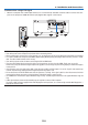
Design and manufacturing conditions for the stand
1. Todisplayimagesinportraitorientation,useasafetycover(soldseparately).(→page137)
2. Pleasehireaninstallationserviceprovider(forafee)forthedesignandmanufactureofacustomizedstandtobe
usedforportraitprojection.Pleaseensurethatthedesigncomplieswiththefollowingconditions:
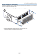
• Thereisanintakeventopeningonthesafetycover.Donotobstructthisopening.
• Thereare2ventilationholesatthebottomoftheprojector.Theseholesshouldremainunobstructed.
• Usethe6screwholesatthebackoftheprojectortosecureittothestand.
Screwholecenterdimension:300×300(pitch=150)mm
Screwholedimensionontheprojector:M4withamaximumdepthof8mm
3ofthelegscanbeunscrewedforremoval.
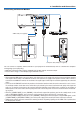
• Horizontaladjustmentmechanism(forexample,boltsandnutsin4places)
• Pleasedesignthestandsothatitdoesnoteasilytoppleover.
* Werecommendcombiningceilingmounts(modelNP15CM,soldseparately)withanangleadjustmentmechanism.
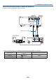
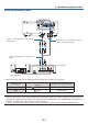
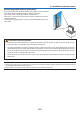
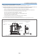
Reference drawings
* Thedrawingshowingthedimensionalrequirementsisnotanactualstanddesigndrawing.
32
34
150
150
34
85
300
[Side View] [Front View]
Screw holes for 6 -
M4 use
□ 84 × 108 holes
(Intake vent)
□ 40 × 78 holes
(Exhaust vent)
(Unit: mm)
Horizontal adjusterIntake vent