
User's Manual

8
1. Introduction
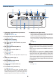
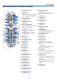
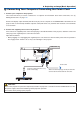
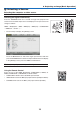
Terminals Features
9 7
1
4
238
1312
1011
56
1. COMPUTER1IN/ComponentInputTerminal
(MiniD-Sub15Pin)
(→page13,125,131,166)
2. DisplayPortINTerminal(DisplayPort20Pin)
(→page126,166)
3. HDMIINTerminal(TypeA)
(→page126,128,132,166)
4. BNCInput[R/Cr/CV,G/Y/Y,B/Cb/C,H,V]Termi-
nals(BNC×5)
(→page125,130)
5. BNC(Y/C)InputTerminal(BNC×2)
(→page130)
6. BNC(CV)InputTerminal(BNC×1)
(→page130)
7. USBPort(TypeA)
(→page167)
(Forfutureexpansion.Thisportallowsforpowersup-
ply.)
8. HDMIOUTTerminal(TypeA)
(→page129)
9. Ethernet/HDBaseTPort(RJ-45)
(→page133,134,167)
10.3DSYNCTerminal(MiniDIN4Pin)
(→page40)
11.PCCONTROLPort(D-Sub9Pin)
(→page167,173)
Use this port to connect a PC or control system.
Thisenablesyoutocontroltheprojectorusingserial
communicationprotocol.Ifyouarewritingyourown
program,typicalPCcontrolcodesareonpage173.
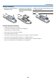
12.REMOTETerminal(StereoMini)
Usethisjackforwiredremotecontroloftheprojector
usingacommerciallyavailableremotecablewith⌀3.5
stereomini-plug(withoutresistance).
Connecttheprojectorandthesuppliedremotecontrol
usingacommerciallyavailablewiredremotecontrol
cable.
(→
page11)
NOTE:
• WhenaremotecontrolcableisconnectedtotheREMOTE
terminal, infrared remote control operations cannot be per-
formed.
• PowercannotbesuppliedfromtheREMOTEterminaltothe
remote control.
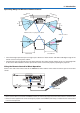
• When [HDBaseT] is selected in the [REMOTE SENSOR]
and the projector is connected to a commercially-available
transmissiondevicethatsupportsHDBaseT,remotecontrol
operations in infra-red cannot be carried out if transmission
of remote control signals has been set up in the transmission
device.However,remotecontrolusinginfraredrayscanbe
carried out when the power supply of the transmission device
is switched off.
13. SLOT
(→page157)