Wall Mount Unit NP04WK/NP04WK1 Installation and Adjustment Manual NP04WK-IAM-01
Wall Mount Unit NP04WK/NP04WK1 Installation and Adjustment Manual Thank you for your purchase of this NEC wall mount unit. Please read this installation and adjustment manual carefully to ensure proper use. For a list of the supported projectors, please see the NEC website or NEC catalogs. The descriptions in the installation and adjustments manual are mainly for the NPUM330X. Special skills are required to install the wall mount unit. This work should never be performed by the customer.
Please heed the following Symbol In this “Installation and Adjustment Manual”, to ensure the safe and proper use of the product, prevent harm to yourself and others and damage to property, various symbols are used. The symbols and meanings are as follows. Please read this manual after ensuring the contents are well understood. Warning Improper handling and ignoring this indication may result in bodily harm such as death, serious injury and so on.
Warning • Do not install in places subject to constant vibration. Extended vibration may cause loosening of the screws and result in the Wall Mount Unit and projector falling and causing injury. Also, it may cause breakdown of the projector. • To ensure safety, be sure to tighten the bolts, screws and safety lock screws securely. Failure to do so may result in the projector falling and causing injury. • Do not modify any parts.
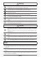
Introduction M Packaged Parts Check that the parts below are included in the package. Wall adapter: 1 set Slide arm: 1 set The wall adapter and slide arm are assembled upon shipment. Wall adapter covers: 2 These are covers for the wall adapter. The two covers are the same. Washers: 4 Spacers: 4 These are used to mount the wall adapter to the wall. * For the bolts or screws for mounting the wall adapter to the wall, use bolts or screws that are adapted to the wall surface.
M Names of Parts (Wall adapter) Cable hole Wall adapter cover Elongated wall mount screw holes Wall adapter cover Fixing screw (A) (Arm unit) Vertical position reference line Wall adapter (wall adapter unit + arm unit) View from above Cap Slide arm Left/right tilt adjustment knob Safety lock screws (2) Cable hole Fixing screws (B) (2) Horizontal title adjustment knob (Mount plate) Vertical title adjustment knob Cable hole Elongated wall mount screw holes View from below ENG-5
M Dimensions of Parts The following shows an external view of the wall mount unit, the positions of the wall adapter’s wall mount screws and the amount of movement when mounting the projector. 530 Units: mm Center of wall adapter 60 572 (min.) to 994 (max.) (When wall plate mounted: 575 (min.) to 997 (max.) 223 189 422 (arm unit movement range) Center of wall adapter Center of wall adapter Wall adapter mount screw positions 142 ±40 (arm unit movement range) 100 189 94.
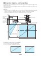
M Projection Distance and Screen Size The following shows the projection distance and screen size as well as the optimum height of the projector and screen. Refer to the dimensions on the diagram to determine the position of installation, then perform the mounting procedure. CAUTION - When the screen is installed in front of the wall surface, the distance between the projector and the screen will be shorter (the sliding range is reduced). Check before installing.
NP-UM330X/NP-UM280X Screen Size (D) 61.5 70 80 90 100 Projection distance W (width) x H2 (height) (cm) 125.0 142.2 162.6 182.9 203.2 93.7 106.7 121.9 137.2 152.4 L1 (cm) L2 (cm) 10.5 16.8 24.1 31.5 38.8 44.8 51.1 58.5 65.8 73.2 Height between wall adapter’s lower edge screw hole center and screen’s upper edge – H1 (cm) 21.2 23.1 25.4 27.6 29.9 NP-UM330W/NP-UM280W Screen Size (D) 58 60 70 80 90 100 Projection distance W (width) x H2 (height) (cm) 124.9 129.2 150.8 172.3 193.9 215.4 78.1 80.8 94.
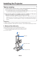
Installing the Projector Before installing 1. Consider the place where the screen is to be installed and determine the position in which the wall mount unit is to be mounted. (See page ENG-7) - It is not possible to install in such a way that the image is projected at an angle. Position in such a way that the image is projected directly to the front. 2. Check that the position of installation meets the conditions in “Be sure to read before installing” on page ENG-2 of these instructions.
2. Attach the wall adapter to the wall’s structural material. Use the included washers and spacers to attach the wall adapter with the M6 screws (or bolts). - For the position for mounting the wall adapter onto the wall and the dimensions, see “Dimensions of Parts” on page ENG-6 and “Projection Distance and Screen Size” on page ENG-7. - Be sure to fasten the screws at the center of the mount holes, as they will serve as the reference points for the horizontal position.
4. Insert the slide arm on the arm unit. Arm unit Slide arm 5. Attach the safety lock screws and fixing screws (B). (1) Use the included hexagonal wrench to securely tighten the two safety lock screws. (2) Leave the two fixing screws (B) loose. Tighten them after adjustments are made. (1) Safety lock screws (2) Fixing screws (B) * This diagram is as seen from below.
6. Make the initial setting of the arm unit’s vertical position. Upon shipment from the factory, the arm unit is set to the uppermost position. (1) Loosen the arm unit’s fixing screw (A), then holding the arm unit’s base, lower the arm unit to the lowermost position. (2) Temporarily fasten the fixing screw (A). This completes the initial setting of the arm unit’s vertical position. (1) (2) Fixing screw (A) Arm unit WARNING - Do not remove the safety lock screws other than for assembly.
7. Cabling The power cord and signal cable(s) can be passed through the slide arm and wall adapter. There is one cable hole in the slide arm and three cable holes in the wall adapter (upward, throughto-wall and downward). Select the cable holes to be used according to the cabling conditions. (1) Pass the cables through the cable hole in the slide arm then to the tip of the arm unit. (2) Pass the cables through the upper, lower or middle cable hole in the wall adapter.
Adjusting for Distortion of the Projected Image M Before Adjusting Preparing the projector - - Project an image from the projector, then first move the projector’s focus ring to roughly adjust the focus of the projected image. For instructions on projecting images, see “Projecting Images (Basic Operation)” of the user’s manual (CD-ROM) supplied with the projector. At “Installation” or “Settings” on the on-screen menu, select “Ceiling/Front” for the projection method.
2. Adjust the projector’s tilt in the vertical direction. Vertical tilt adjustment knob Turn the vertical tilt adjustment knob and adjust so that the left and right edges of the projected image are parallel. - The adjustment range is ±5°. 3. Adjust the projector’s tilt in the rotational direction. Turn the left/right tilt adjustment knob and adjust so that the image is parallel to the screen. - The adjustment range is ±5°.
4. Adjust the size of the projected image. Safety lock screws (1) Loosen the arm unit’s two fixing screws (B). (2) Holding the slide arm’s cap, move forward or backward to project the image over the entire screen. - When installed following the instructions under “Projection Distance and Screen Size”, the image is projected at about the center. - The slide arm moves a maximum of 422 mm.
5. Adjust in the vertical direction. Fixing screw (A) Loosen the fixing screw (A), then hold the base of the arm and move the arm upwards, targeting the reference line. Adjust so that the projected image is at the center of the screen surface. * If the projected image moves too far upwards with respect to the screen surface, it is easier to adjust by first holding the base of the arm and lowering the arm, then moving it back upwards.
7. Once the adjustments are completed, securely tighten all the screws that were loosened. 8. Attach the covers to the wall adapter. Cover (A) and cover (B) have the same shape. Attaching the covers (1) Push one of the covers onto the wall adapter. - The four tabs on the back of the cover fit into the notches in the wall adapter, fixing the cover in place. (2) Insert cover (B) from an angle, then rotate it, paying attention to the tabs.
9. Attach the cable cover to the projector. For instructions on attaching the cover, see the user’s manual. WARNING - Do not bundle the power cord together with the cables and put it under the cable cover. Doing so could result in fire. This completes installation and adjustment.
Specifications Product name Model name Adjustable angles Adjustable positions External dimensions Weight Load capacity : : : : : : : Wall mount unit NP04WK Vertical angle – ±5°; Horizontal angle – ±5°; Tilt angle – ±5° Front/back – 422; Horizontal – ±50 mm; Vertical – ±40 mm 530 (W) x 572 (D) x 223 (H) mm (NP04WK1; 530 (W) x 575 (D) x 223 (H) mm) Approx. 9.3 kg (NP04KW1: 11.2 kg) 7.0 kg These specifications and the design are subject to change without notice.