MultiSync PA322UHD User’s Manual
Index Warning, Caution ..........................................................................................................................English-1 Registration Information ...............................................................................................................English-2 Recommended use ......................................................................................................................English-3 Product Features ..................................................
TO PREVENT FIRE OR SHOCK HAZARDS, DO NOT EXPOSE THIS UNIT TO RAIN OR MOISTURE. ALSO, DO NOT USE THIS UNIT’S POLARIZED PLUG WITH AN EXTENSION CORD RECEPTACLE OR OTHER OUTLETS UNLESS THE PRONGS CAN BE FULLY INSERTED. REFRAIN FROM OPENING THE CABINET AS THERE ARE HIGH VOLTAGE COMPONENTS INSIDE. REFER SERVICING TO QUALIFIED SERVICE PERSONNEL. CAUTION CAUTION: TO REDUCE THE RISK OF ELECTRIC SHOCK, MAKE SURE POWER CORD IS UNPLUGGED FROM WALL SOCKET.
Registration Information FCC Information 1. Use the attached specified cables with this monitor so as not to interfere with radio and television reception. (1) The power supply cord you use must have been approved by and comply with the safety standards of U.S.A., and meet the following condition. Power supply cord Length Plug shape Non shield type, 3-conductor 2.0 m U.S.A (2) 2. Please use the supplied shielded video signal cable.
Safety Precautions and Maintenance FOR OPTIMUM PERFORMANCE, PLEASE NOTE THE FOLLOWING WHEN SETTING UP AND USING THE LCD COLOR MONITOR: • DO NOT OPEN THE MONITOR. There are no user serviceable parts inside and opening or removing covers may expose you to dangerous shock hazards or other risks. Refer all servicing to qualified service personnel. • Do not spill any liquids into the cabinet or use your monitor near water.
CORRECT PLACEMENT AND ADJUSTMENT OF THE MONITOR CAN REDUCE EYE, SHOULDER AND NECK FATIGUE. CHECK THE FOLLOWING WHEN YOU POSITION THE MONITOR: • For optimum performance, allow 20 minutes for the display to warm up. • Adjust the monitor height so that the top of the screen is at or slightly below eye level. Your eyes should look slightly downward when viewing the middle of the screen. • Position your monitor no closer than 40 cm (15.75 inches) and no further away than 70 cm (27.56 inches) from your eyes.
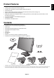
English Product Features • DisplayPort and HDMI, which support 10-bit color depth. • 5-setting, easy-to-switch picture mode (see page 14). • Accurate color reproduction for high-end graphic design (see page 18). • Quick warmup time. • Picture-in-picture/picture-by-picture multi-screen mode includes real-time preview (see page 14). • USB hub with two upstream ports (see page 15).
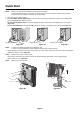
Quick Start To connect the LCD monitor to your system, follow these instructions: NOTE: Make sure to read “Recommended Use” (page 3) before installation. In order to display the maximum resolution, a video card that can output a resolution of 3840 x 2160 is needed. The monitor must be installed or carried by two or more people. 1. Turn off the power to your computer. 2.
NOTE: Incorrect cable connections may result in irregular operation, damage display quality/components of LCD module and/or shorten the module’s life. NOTE: When you use DVI signal, please select DVI in HDMI/DVI SELECT in Advanced Menu Tag9 or on NO SIGNAL OSD warning (see page 17). DisplayPort (DISPLAYPORT2)*3 30° Tilt USB downstream*2 A Type Highest Stand Position A Type B Type B Type USB upstream2 USB upstream1 USB downstream DVI-D HDMI Headphone DVI-D Figure C.
7. Slide down the cable cover (Figure D.1). 8. Connect one end of the power cord to the AC inlet on the back of the monitor and the other end to the power outlet. NOTE: Please refer to Caution section of this manual for proper selection of AC power cord. Figure D.1 9. Turn on the monitor with the front power button (Figure E.1) and the computer. 10. Refer to the Controls section of this User’s Manual for a full description of these OSD controls.
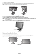
Before rotating, the screen must be raised to the highest level and tilt to avoid knocking the screen on the desk or pinching your fingers. Disconnect all cables. To raise the screen, place hands on each side of the monitor and lift up to the highest position (Figure RL.1). To rotate screen, place hands on each side of the monitor screen and turn clockwise from Landscape to Portrait or counterclockwise from Portrait to Landscape (Figure R.1).
Flexible Arm Installation This LCD monitor is designed for use with a flexible arm. To prepare the monitor for alternate mounting purposes: NOTE: The monitor must be installed or moved by two or more people. • Follow the instructions provided by the manufacturer of the display mount. • To meet the safety requirements, the monitor must be mounted to an arm that supports the weight of the monitor. See page 26 for details. Remove the monitor stand before mounting.
1. Turn off the power of your computer, monitor and other connected equipments. 2. Connect attached thumbscrews to the holes on DisplayPort’s interface unit (Figure G.1). Figure G.1 3. Disconnect outside screws (Figure G.2). Figure G.2 4. Pull out the DisplayPort interface unit using the thumbscrews (Figure G.3). Figure G.3 NOTE: When you use option board accessories, please contact your supplier for detailed information. Refer to the option board’s manual for further information.
Controls Many of the OSD controls are also available in the included MultiProfiler software, developed by NEC Display Solutions. The latest MultiProfiler software is available on the NEC Display Solutions website. OSD (On-Screen Display) control buttons on the front of the monitor function as follows: To access OSD menu, press the MENU button. To change signal input, press the SELECT button. NOTE: OSD must be closed in order to change signal input.
• Use the control buttons (LEFT/RIGHT or UP/DOWN or MENU) to access the “LANGUAGE SELECTION” menu. • Press the LEFT/RIGHT or UP/DOWN buttons to select the desired OSD language. • To exit from this OSD menu, press EXIT button. NOTE: Setting the OSD language is only necessary upon initial setup. The OSD language will stay the same until changed by the user. Brightness Controls BRIGHTNESS Adjusts the overall image and background screen brightness.
Color Control Systems PICTURE MODE Changes the Picture mode that is most suitable for the type of content that is shown. 5 Picture modes are available to be customized. See Advanced menu Tag1 PICTURE MODE (page 19) and “Using the PICTURE MODE function” (page 18) for more information. WHITE Adjusts the white temperature to NATIVE or a specific color temperature using this setting. A lower color temperature will make the screen reddish and a higher color temperature will make the screen bluish.
Selects the size of the sub-picture used in PIP mode. MULTI PICTURE OFF PICTURE PATTERN - PIP Picture 1 Picture 2 Picture 3 Picture 4 - - - - - - - PBP 2 - - PBP 4 PBP (Portrait mode) 4 PICTURE is OFF in ROTATION in Advanced Menu TagA PICTURE is ON in ROTATION in Advanced Menu TagA USB SELECT Change USB upstream input (1 or 2) associated with the current display input.
MENU Tools LANGUAGE OSD control menus are available in nine languages. OSD LEFT/RIGHT You can choose where you would like the OSD control image to appear on your screen. Selecting OSD Location allows you to manually adjust the position of the OSD control menu left or right. OSD DOWN/UP You can choose where you would like the OSD control image to appear on your screen. Selecting OSD Location allows you to manually adjust the position of the OSD control menu Up or Down.
CARBON USAGE: Displays the estimated carbon usages information in kg. This is the arithmetic estimation, not actual measurement value. This estimation is based without any options. COST SAVINGS: Displays the electricity cost savings in balance. CARBON CONVERT SETTING: Adjusts the carbon footprint factor in the carbon saving calculation. This initial setting is based on the OECD (2008 Edition). CURRENCY SETTING: Displays electricity pricing in 6 currency units.
Using the PICTURE MODE function Choose the Picture Mode that is most suitable for the type of content that is shown. There are several types of mode (sRGB, Adobe®RGB, DCI, REC-Bt709, HIGH BRIGHT, FULL, DICOM, PROGRAMMABLE). • Each PICTURE MODE includes BRIGHTNESS, AUTO BRIGHTNESS, WHITE, Color Gamut, GAMMA, BLACK, UNIFORMITY, COLOR VISION EMU, METAMERISM, RESPONSE IMPROVE, AMBIENT LIGHT COMP., 6-Axis ADJUST settings. You can change these settings in Tag1 advanced menu.
If you need detailed information about the controls, please use the advanced menu. There are 2 ways to access the advanced menu. Method 1: • Press the Menu button to access OSD menu. Use the front buttons to move the cursor to the ADVANCED SETTING in Color control systems. Press INPUT button to open the advanced OSD. • Press the EXIT button. Method 2: • Turn off the monitor.
GAMMA Allows you to manually select the brightness level of grayscale. There are five selections: sRGB, L Star, DICOM, PROGRAMMABLE and CUSTOM. sRGB: GAMMA setting for sRGB. L Star: GAMMA setting for eciRGB_v2 and Lab color space. DICOM: DICOM GSDF (Grayscale Standard Display Function) is typically used for medical imaging. PROGRAMMABLE: The settings can be changed to your preference by downloading the application software. You can select this when PICTURE MODE is PROGRAMMABLE.
This function electronically compensates for the slight variations in the white uniformity level as well as for deviations in color that may occur throughout the display area of the screen. These variations are characteristic of LCD panel technology. This function improves the color and evens out the luminance uniformity of the display. NOTE: Using the UNIFORMITY feature does reduce the overall peak luminance of the display.
Tag6 V.RESOLUTION Adjusts the vertical size by increasing or decreasing the setting. Press “RIGHT” button to expand the height of the image on the screen. Press “LEFT” button to narrow the height of the image on the screen. EXPANSION Sets the zoom method. FULL: The image is expanded to full screen, regardless of the resolution. ASPECT: The image is expanded without changing the aspect ratio. OFF: The image is not expanded.
LANGUAGE*1 OSD control menus are available in nine languages. Press “LEFT” or “RIGHT” to select. OSD H.POSITION You can choose where you would like the OSD control image to appear on your screen. Selecting OSD Location allows you to manually adjust the position of the OSD control menu left or right. OSD V.POSITION You can choose where you would like the OSD control image to appear on your screen. Selecting OSD Location allows you to manually adjust the position of the OSD control menu up or down.
PICTURE PATTERN Selects split screen mode when MULTI PICTURE is “PBP”. You can select 2 or 4 split screen types. ACTIVE PICTURE Selects active picture when set to other than OFF in MULTI PICTURE. A white frame is displayed on selected picture. EXPANSION Sets the zoom method. FULL: The image is expanded to full screen, regardless of the resolution. ASPECT: The image is expanded without changing the aspect ratio. OFF: The image is not expanded.
TagB TagC DDC/CI ENABLE/DISABLE: Turns on or off the two way communication and control with connected PC by video cable. NOTE: Set DDC/CI to ENABLE when using hardware calibration software like MultiProfiler over DisplayPort, DVI or HDMI. SCREEN SAVER Use the SCREEN SAVER to reduce the risk of image persistence. MOTION (Default OFF): Screen image moves periodically in 4 directions in order to reduce the risk of image retention.
Specifications Monitor Specifications MultiSync PA322UHD Notes LCD Module 80.1 cm/31.5 inches 80.1 cm/31.5 inches 3840 x 2160 Active matrix; thin film transistor (TFT) liquid crystal display (LCD); 0.182 mm dot pitch; 350 cd/m2 white luminance; 1000:1 contrast ratio (typical). DisplayPort Connector: Digital RGB DisplayPort Complies with Standard V1.
DisplayPort: DisplayPort is designed to be the future-ready, scalable solution for high performance digital display connectivity. It enables the highest resolutions, the fastest refresh rates and deepest color depths over standard cables. HDMI: HDMI is designed to be the future-ready, scalable solution for high performance digital display connectivity. It enables the highest resolutions, the fastest refresh rates and deepest color depths over standard cables, especially for consumer audio/video equipment.
Troubleshooting No picture • The signal cable should be completely connected to the display card/computer. • The display card should be completely seated in its slot. • The monitor does not support a DisplayPort converter signal. • The front power button and computer power switch should be in the ON position. • Check to make sure that a supported mode has been selected on the display card or system being used. (Please consult display card or system manual to change graphics mode.
• If the brightness fluctuates make sure AUTO BRIGHTNESS is turned off. • In PICTURE MODE, set HIGH BRIGHT. See page 18. • LCD brightness degradation occurs due to long-term usage or extreme cold conditions. • When the display cannot achieve the desired brightness, the numerical brightness value on the OSD will blink. • When using an HDMI input, please change “VIDEO LEVEL”. Display image is not sized properly • Use the OSD Image Adjust controls to increase or decrease the Coarse adjustment.
Using the Auto Brightness function The brightness of the LCD screen can be set to increase or decrease depending on the amount of ambient light within the room. If the room is bright, the monitor becomes correspondingly bright. If the room is dim, then the monitor will dim accordingly. The purpose of this function is to make the viewing experience more comfortable to the eye in a variety of lighting conditions. The Auto Brightness function is set to OFF by default.
Simply connect the external USB color sensor, and re-calibrate the factory settings without the need of a computer. This feature is to compensate for a yellow color shift that typically occurs with long-term LCD usage. All PICTURE MODES are updated when Self Calibration is performed. Before proper self calibration can be performed, display should warm-up for a minimum 30 minutes. If this calibration is started before the monitor is warmed up, a warning will appear on-screen (Figure S.2).
6. The procedure will ask for the USB color sensor to be placed on the center of the display panel (Figure S.3). Tilt the display panel approximately 5˚ backward and place the USB color sensor in the center of the display panel (Figure S.1). NOTE: Place the USB color sensor flat against the LCD to avoid external light contamination. DO NOT press the calibrator against the display panel. Press “SELECT” to start the calibration. Stand-alone calibration may take several minutes depending on user settings.
The white point can be copied from one display to one or more additional displays. Using this feature reduces the variation between different displays allowing them to match each other more closely. White Point Matching/Copy does not compensate for a typical yellow color shift due to long-term LCD usage. If this yellow shift is noticeable, please do Self Calibration. See page 31. NOTE: Stand-alone calibration can only be performed using the MDSVSENSOR3.
8. Press SELECT to start the confirmation of white point. 9. After the confirmation is finished, FINE TUNING MODE message appears. 10. At the FINE TUNING MODE message (Figure C.6), press SELECT if the copy result is satisfactory. If the copy result is unsatisfactory, manually fine tune the white point using the “LEFT” and “RIGHT” buttons, and press SELECT. 11. To end the calibration mode, press “EXIT”. Figure C.
NEC DISPLAY SOLUTIONS is strongly committed to environmental protection and sees recycling as one of the company’s top priorities in trying to minimize the burden placed on the environment. We are engaged in developing environmentallyfriendly products, and always strive to help define and comply with the latest independent standards from agencies such as ISO (International Organisation for Standardization) and TCO (Swedish Trades Union).