Version 1.3.
| NEC PD COMMS TOOL - USER’S GUIDE Software Updates Occasionally updates and enhancements to the NEC PD Comms Tool software will be made available. Use the Check for updates feature in the software to automatically see if a newer version is available. Technical Support and Feedback For technical support with the NEC PD Comms Tool product, please check for any Frequently Asked Questions that may help to solve the issue.
| NEC PD COMMS TOOL - USER’S GUIDE Table of Contents Contents Precautions: . . . . . . . . . . . . . . . . . Note: . . . . . . . . . . . . . . . . . . . . Supported Display Monitors. . . . . . . . . . . . System Requirements . . . . . . . . . . . . . . What’s new in this version . . . . . . . . . . . . 5 5 6 7 7 Introduction Overview . . . . . . . . . . . . . . . . . . .
| NEC PD COMMS TOOL - USER’S GUIDE SETOPCODE command . . . . . . . . . . . . WAIT command . . . . . . . . . . . . . . . SENDIR command . . . . . . . . . . . . . . SCHEDULE command . . . . . . . . . . . . Further Script Examples . . . . . . . . . . . . Table of Contents 44 44 45 45 48 Example Display Connections 49 Configuring Connections . . . . . . . . . . . . 49 About Monitor IDs. . . . . . . .
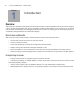
| NEC PD COMMS TOOL - USER’S GUIDE Precautions: • This software application allows many advanced features of the display to be adjusted. Care should be taken when making any adjustments to avoid misadjustment. Important Notes: • This document covers both the Mac OS and Windows versions of the NEC PD Comms Tool software. The features and functions of both versions are identical unless noted otherwise.
| NEC PD COMMS TOOL - USER’S GUIDE Supported Display Monitors NEC PD Comms Tool supports the following NEC display monitor models: • NEC P Series (P401, P461, P521 etc.) • NEC X Series (X461UN, X461HB, X431BT etc.) including UHD models such as the X841UHD • NEC S Series (S401, S461, S521 etc.) • NEC M Series (M401, M461 etc.) • NEC Exx2 series (E322, E422, E462, E552 etc.
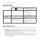
| NEC PD COMMS TOOL - USER’S GUIDE System Requirements NEC PD Comms Tool has the following system requirements: Mac OS Operating System Apple Mac OS X v10.5 or higher. ÿ Microsoft Windows Microsoft Windows XP, XP x64, Windows Server 2003, Windows Vista (32 or 64 bit), Windows 7 (32 or 64 bit), Windows 8 or 8.1 (32 or 64 bit).
| NEC PD COMMS TOOL - USER’S GUIDE Chapter 1 Introduction Overview NEC PD Comms Tool (NEC Public Display Communications Tool) is a software application that can be used to configure, control, and test supported NEC large screen LCD display models via either RS232 or LAN connections. It can also be used to assist with developing and debugging external control systems by showing the communications protocol for commands exchanged between the software and displays.
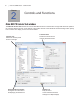
| NEC PD COMMS TOOL - USER’S GUIDE Chapter 2 Controls and Functions Main NEC PD Comms Tool window The NEC PD Comms Tool window has a list of selectable functions on the left side. The right side shows the panel for the currently selected function. At the bottom of the window are the Communications Interface settings which specify how to connect to a display, such as via LAN or RS232.
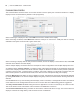
| NEC PD COMMS TOOL - USER’S GUIDE Communications Interface The Communications Interface section on the main window is used to specify the connection interface to a display. Displays can be connected either by RS232 or LAN (if supported). When connecting to a display via LAN, select LAN and enter the IP address of the display. When connecting via RS232, select RS232 and select the COM port on the host PC. COM ports that are currently available on the system are shown with a green check mark.
| NEC PD COMMS TOOL - USER’S GUIDE Display List The Display List allows Communications Interface settings for multiple displays to be stored for easy access by selecting from a list. This is useful for example when there are multiple displays in use, as it allows the communications configuration for each to be stored, and accessed quickly by selecting from the list.
| NEC PD COMMS TOOL - USER’S GUIDE Main Window - Function List Controls - By OpCode panel The Controls - By OpCode panel provides access for Get (reading) and Set (writing) control settings. Each control has an Op Code number assigned. See the protocol specification document for your model of display for a list of supported controls and Op Codes.
| NEC PD COMMS TOOL - USER’S GUIDE Controls - Power panel The Controls - Power panel controls the power settings of the displays. Clicking the On button will turn the display or displays on. Clicking the Off button will turn the display or displays off. The Current State of the display is shown. The Power On Delay time control sets the time delay is seconds for the display to when the main display circuits are switched on after power on.
| NEC PD COMMS TOOL - USER’S GUIDE Controls - Power Save Mode panel The Controls - Power Save Mode panel controls the power settings of the displays. Power Saving Mode (Legacy) can be enabled and disabled for the currently selected video input using Enable and Disable. On some display models the type of Power Save Mode can be selected, as well as the delay time for entering power save after loss of video signal. The Reply Status shows the reply from the display for this command.
| NEC PD COMMS TOOL - USER’S GUIDE Controls - Video & Color panel The Controls - Video & Color panel controls the video signal and color adjustments. The Brightness, Contrast, Sharpness, Black Level, Tint, Color, Gamma, Picture Mode and Red Green and Blue Gains controls adjust the settings for the respective video controls in the display.
| NEC PD COMMS TOOL - USER’S GUIDE Controls - Size & Position panel The Controls - Size & Position panel has controls used to configure the various video size and position settings in the display.
| NEC PD COMMS TOOL - USER’S GUIDE Controls - Tile Matrix panel The Controls - Tile Matrix panel has controls used to configure the tile Matrix settings for dividing and expanding a video source over multiple displays. Enable Tile Matrix - Is used to enable the Tile Matrix feature in the display. Matrix size - Is used the set the matrix size in rows and columns. Use Tile Comp - Enables the Tile Comp feature to compensate for the display bezel width when the video is divided.
| NEC PD COMMS TOOL - USER’S GUIDE Controls - Cooling Fans panel The Controls - Cooling Fans panel has controls used to adjusts the cooling fan settings such as fan speed, temperature trigger point, and forced on or automatic operation.
| NEC PD COMMS TOOL - USER’S GUIDE Status panel The Status panel reports various aspects about the display. Model Name - Shows the model name read from the display. Serial Number - Shows the serial number read from the display. Operating Hours On - Shows the number of hours that the display has been power on (LCD panel active). Total Operating Hours - Shows the total number of hours that the display has had AC power applied.
| NEC PD COMMS TOOL - USER’S GUIDE IR Remote panel The IR Remote panel can be used to perform the equivalent operations as the physical IR Remote control using the software and communicating using the LAN or RS232 connection to the display. This is useful when it is not practical to use the actual IR Remote control with the display, or when it is necessary to access controls by remote that are not available from within the software. Click the buttons to send the IR Remote command to the display.
| NEC PD COMMS TOOL - USER’S GUIDE Commands - Clock & Schedule panel The Clock & Schedule panel can be used to set the internal real time clock and schedule functions in the display. Various scheduled operations such as power on, power off, and changing inputs can be configured. Once a schedule has been created in a display, it will perform the operations on its own, and it is not necessary to keep this software running.
| NEC PD COMMS TOOL - USER’S GUIDE Commands - Daylight Savings panel The Daylight Savings panel uses the daylight savings commands available on some display models to set the internal daylight savings parameters of display.
| NEC PD COMMS TOOL - USER’S GUIDE Commands - Firmware Version panel The Firmware Version panel uses the firmware version command to read the various firmware versions in the display. The index control selects the particular sub-version to read. Firmware 1 version corresponds to Index 0.
| NEC PD COMMS TOOL - USER’S GUIDE Commands - LAN MAC Address panel The LAN MAC Adddress panel uses the MAC address command to read the LAN interface’s MAC address.
| NEC PD COMMS TOOL - USER’S GUIDE Commands - TV Tuner Channel panel The TV Tuner Channel panel uses the TV tuner commands to read and write the current channel on models equipped with a TV tuner.
| NEC PD COMMS TOOL - USER’S GUIDE Commands - Security panel The Security panel uses the security commands to read and write the current enable status of the security setting. If currently enabled, the correct password must be supplied in order to disable the security setting when using Write. Enabling Security will require that in order to use the display, the password be entered on the OSD using the IR remote after AC power is applied.
| NEC PD COMMS TOOL - USER’S GUIDE Commands - Input Name panel The Input Name panel uses the input name commands to read, write, and reset the name of the current video input shown on the display’s OSD.
| NEC PD COMMS TOOL - USER’S GUIDE Commands - Auto ID panel The Auto ID panel uses the auto ID commands to reset and start the Auto ID process when multiple displays are daisychained via LAN. When using the Auto ID function, be sure to select the Communications Interface settings to the first display in the LAN daisy-chain. Note: The physical ordering of the LAN cables determines the order in which Monitor IDs are assigned. Note: The correct LAN connections on each display must be used.
| NEC PD COMMS TOOL - USER’S GUIDE Commands - Auto Tile Matrix panel The Auto Tile Matrix panel uses the auto tile matrix commands to reset and start the Auto Tile Matrix process when multiple displays are daisy-chained via LAN. When using this function, be sure to select the Communications Interface settings to the first display in the LAN daisychain. All of the displays in the daisy-chain should be powered on.
| NEC PD COMMS TOOL - USER’S GUIDE Commands - Proof Of Play panel The Proof Of Play panel uses the proof of play commands to start, stop, and read the logs from the display. The Proof Of Play logs are cleared when AC power is lost. On some models the logs are also cleared when the display enters standby (power saving) mode. Note: Currently the From and To settings must be the same value. So only a single log can be read per command.
| NEC PD COMMS TOOL - USER’S GUIDE Commands - Simple Commands panel The Simple Commands panel can be used to send simplified commands to the display. These commands (if supported by the display) can be used to control the power state, video input and picture mode. They are intended as a simple alternative to the more complex commands used elsewhere which require calculating a checksum etc. These simple commands do not support the concept of a Monitor ID.
| NEC PD COMMS TOOL - USER’S GUIDE Advanced - Analog Video panel The Analog Video panel can be used to make advanced adjustments to the internal analog-to-digital converters of the display. These controls are only available when analog video inputs such as VGA, RGB/HV, and Option-Analog. Analog Auto-Setup will measure the incoming analog video signal and automatically set the video level controls in the display as well as the size and position of the video.
| NEC PD COMMS TOOL - USER’S GUIDE Black LUT - Creates a special LUT used to assist with adjusting analog bias. White LUT - Creates a special LUT used to assist with adjusting analog gain. Advanced - Scripting panel The Scripting panel is used to load, select and run script files. The scripting function allows complex command sequences to be performed on multiple displays via a powerful but simple scripting language.
| NEC PD COMMS TOOL - USER’S GUIDE • SETMONITORID - Sets the Monitor ID of the display(s) to perform commands on. • SETPOWER - Sets the power status of the display(s). • SETDATETIME - Sets the internal clock on the display(s) to the current system date and time. • SETOPCODE - Sets the value of an Op Code control. • WAIT - Pauses between commands. • SENDIR - Sends a sequence of IR Remote commands equivalent to pressing the buttons on the IR Remote.
| NEC PD COMMS TOOL - USER’S GUIDE • Some Op Codes are only supported in certain operating modes. • Displays may support additional Op Code names not listed in this table. In this case use the Op Code HEX value. • For controls that have discrete values such as “on” and “off”, the supported names are listed. These names can be used in scripts to set the value of an Op Code control instead of using a numerical value.
| NEC PD COMMS TOOL - USER’S GUIDE Advanced - IP Scan panel The IP Scan panel is used to scan a range of IP addresses and check to see if there is a display with a LAN interface on each IP address, and if it is responding correctly. This is similar to a “ping” function. If a display LAN interface is detected, it will attempt to query the display for a model name, serial number and Monitor ID.
| NEC PD COMMS TOOL - USER’S GUIDE Advanced - Operating Mode panel The Operating Mode controls can be used to change the current adjustment mode of the monitor’s OSD (On Screen Display), and allow access to several advanced controls. Note: Only use this control if instructed to do so by NEC personnel. Always return the Operating Mode back to Normal when completed.
| NEC PD COMMS TOOL - USER’S GUIDE Advanced - OpCode Scanner panel The OpCode Scanner function scans all available Op Codes to find out which ones have changed in value. This is useful for example to find out the Op Code of an unknown control, or to find out what other controls change when an operating mode is changed. It works by first reading all of the Op Code values. Next the control setting should be changed via the display’s OSD. Then it will re-read all Op Code values and report any differences.
| NEC PD COMMS TOOL - USER’S GUIDE Advanced - Test Patterns panel The Test Patterns function enables the display’s internal test pattern generator. This is useful when it is necessary to evaluate the display screen independently of any video source signal. Note: When enabled all video input signals, color and gamma related controls and settings are bypassed. Be sure to disable the test pattern when completed. The red, green, and blue levels can be set individually using the slider controls.
| NEC PD COMMS TOOL - USER’S GUIDE Chapter 3 Frequently Asked Questions This page intentionally left blank.
| NEC PD COMMS TOOL - USER’S GUIDE Chapter 4 Troubleshooting Problem: Test Communications Interface operation fails. Solution: Check that: • Each display is correctly configured to use either then LAN or RS232 interface by confirming the EXTERNAL CONTROL setting on the OSD menu (for models that support RS232 daisy-chaining). Newer models that support LAN daisy-chaining don’t have this setting. • The MONITOR ID is set correctly on the OSD and matches the value assigned in the software.
| NEC PD COMMS TOOL - USER’S GUIDE Chapter 5 Scripting Language This chapter describes the format and syntax of the scripting language. A script file is a simple text file that can be created and edited with any text editing application. Save the file with a .txt extension. When a script file is loaded into the application, it will be parsed and any errors in the script will be reported. Within the script file: • Each command in the script must appear on a new line. • Blank lines are allowed.
| NEC PD COMMS TOOL - USER’S GUIDE addresses in decimal format: FOREACHPORT xxx.xxx.xxx.xxx TO yyy.yyy.yyy.yyy # commands to perform on each IP address. ENDFOREACHPORT Example: FOREACHPORT 192.168.0.10 TO 192.168.0.20 SETMONITORID "All" SETPOWER ON ENDFOREACHPORT Sets the Power to On for all displays between the specified IP addresses. SETMONITORID command This command sets the Monitor ID of the display(s) to perform commands on.
| NEC PD COMMS TOOL - USER’S GUIDE SETOPCODE command This command sets the value of an Op Code control. Use this to change a control setting in the display. Most controls are accessed using this command. Several different syntax formats are available for convenience and readability.
| NEC PD COMMS TOOL - USER’S GUIDE • When performing a setting reset The length of time to wait will vary by model, but typically powering on or off the display can take up to 10 seconds. Changing inputs can take 5 seconds, and performing a reset can take 3 seconds. If a command in the script fails it may be because the monitor is still processing the previous command. In this case try adding a WAIT delay before the failing command.
| NEC PD COMMS TOOL - USER’S GUIDE Use the following syntax to specify the schedule parameters, were x is the schedule number to set, and pppp is a list of the parameters to change. SCHEDULE x pppp All of the parameters for a particular schedule number are entered on a single line, with settings separated by a space.
| NEC PD COMMS TOOL - USER’S GUIDE DISPLAYPORT HDMI PICTUREMODE xxx - sets the Picture Mode to xxxx. Either a numerical value or a name can be specified. Valid Picture Mode names are as follows: LASTSETTING SRGB HIBRIGHT STANDARD CINEMA ISF-DAY ISF-NIGHT AMBIENT-1 AMBIENT-2 ONTIME CLEAR - clears (unsets) the Power On Time for the schedule ONTIME hh:mm - sets the Power On Time to hh hours and mm minutes. Hours should be specified in 24 hour format.
| NEC PD COMMS TOOL - USER’S GUIDE Further Script Examples Further examples of various scripts are installed with the application. See the SampleScripts sub-folder in the NEC PD Comms Tool folder on the Windows start menu.
| NEC PD COMMS TOOL - USER’S GUIDE Chapter 6 Example Display Connections Configuring Connections Displays can be connected to the host PC in a variety of ways using RS232 or LAN, depending on the model. Displays can also be daisy-chained together using RS232 or LAN cables, depending on the model. Daisy-chaining displays can simplify cable wiring, and allows more than one display to be controlled from one access connection, as well as minimizing the lengths and number of cable runs.
| NEC PD COMMS TOOL - USER’S GUIDE Direct LAN Supported display connection configurations RS-232C IN LAN1 RS-232C OUT LAN2 LAN RS-232C IN, OUT, and LAN RS-232C RS-232C IN, LAN 1 and LAN2 Models that have an RJ45 LAN connection can be individually connected directly to a LAN via a hub or switch instead of daisy-chaining displays together. This may require more wiring since each display is individually connected directly to a central LAN hub or switch.
| NEC PD COMMS TOOL - USER’S GUIDE • The RS232 connection from the host PC must connect to the RS232 IN on the first display. • Communications via both LAN and RS232 are not supported at the same time. The type of communications link to use to the display must be selected by OSD setting EXTERNAL CONTROL RS-232C / LAN.
| NEC PD COMMS TOOL - USER’S GUIDE See the following for more information on using the Auto ID function. Using the Auto ID function with a LAN daisy-chain • The LAN2 RJ45 (output) of a display must connect to the LAN1 RJ45 (input) on the next display in a daisy-chain. • Each display must have a unique IP address assigned. • Network hub devices must not be used to create multiple branches of displays along the LAN daisy-chain. All displays must be connected sequentially.
| NEC PD COMMS TOOL - USER’S GUIDE Example: Daisy-chained RS232 with one COM port Supported display connection configurations RS-232C IN RS-232C IN RS-232C OUT RS-232C OUT RS-232C IN and OUT LAN RS-232C IN, OUT, and LAN In this example, the host PC has one RS232 COM port, and all displays are daisy-chained together via RS232. Each display must have a unique MONITOR ID since they are all on the same daisy-chain. The RS232 OUT on the first display is connected to the RS232 IN on the next, etc.
| NEC PD COMMS TOOL - USER’S GUIDE Example: Daisy-chained RS232 with multiple COM ports Supported display connection configurations RS-232C IN RS-232C IN RS-232C OUT RS-232C OUT RS-232C IN and OUT LAN RS-232C IN, OUT, and LAN In this example, the host PC has two RS232 COM ports, and there are two separate daisy-chains. Each display on a daisy-chain must have a unique MONITOR ID.
| NEC PD COMMS TOOL - USER’S GUIDE Example: Single IP LAN with daisy-chained RS232 Supported display connection configurations RS-232C IN RS-232C OUT LAN RS-232C IN, OUT, and LAN In this example, the host PC is connected to the first display via LAN. Subsequent displays are connected together using RS232 daisy-chaining. Each display on a daisy-chain must have a unique MONITOR ID. Important: The first display is configured to use LAN as the EXTERNAL CONTROL on the OSD.
| NEC PD COMMS TOOL - USER’S GUIDE Example: Direct Multi IP LAN Supported display connection configurations LAN1 RS-232C IN LAN2 RS-232C RS-232C OUT RS-232C IN, LAN 1 and LAN2 LAN RS-232C IN, OUT, and LAN In this example, the host PC and each display are individually connected to the LAN via hub. Each display has a unique IP address. Important: Models with only one LAN connection must be configured to use LAN as the EXTERNAL CONTROL on the OSD.
| NEC PD COMMS TOOL - USER’S GUIDE Example: Multi IP LAN using LAN daisy-chain Supported display connection configurations LAN1 LAN2 RS-232C RS-232C IN, LAN 1 and LAN2 In this example displays are daisy-chained together using LAN connections. The host PC is connected to the first display via the LAN1 RJ45 connection, and the LAN2 (output) is connected to the LAN1 (input) on the next display in the daisy-chain. Each display has a unique IP address manually assigned. Display 1 PC IP 192.168.0.
| NEC PD COMMS TOOL - USER’S GUIDE Example: RS232 using LAN daisy-chain Supported display connection configurations LAN1 LAN2 RS-232C RS-232C IN, LAN 1 and LAN2 In this example, the host PC is connected to the first display via RS232. The displays are daisy-chained together using LAN connections. The LAN2 (output) is connected to the LAN1 (input) on the next display in the daisy-chain. Each display has a unique IP address assigned. Display 1 PC COM1 RS232 IN LAN2 ID 1 IP 192.168.0.
| NEC PD COMMS TOOL - USER’S GUIDE Connecting to displays wirelessly Displays can be accessed wirelessly by using a Wireless Router or Access Point connected to the displays as shown in the following example. Important: Make sure any wireless firewall settings on the don’t block communications on port 7142. Display 1 PC IP 192.168.0.200 WIRELESS LAN ROUTER LAN LAN or RS232 ID 1 LAN IP 192.168.0.
| NEC PD COMMS TOOL - USER’S GUIDE Chapter 7 Assigning an IP address Displays connected via LAN need to be assigned an IP address so that they can be remotely accessed. Each display with a LAN interface has a default IP address of 192.168.0.10. This address must be changed in order to avoid conflicts when other displays are connected to the LAN. When the LAN RESET operation is performed on a display’s OSD, the IP address will be reset to the default value.
| NEC PD COMMS TOOL - USER’S GUIDE Next enter a temporary IP address for the PC, such as 192.168.0.255, and a subnet mask of 255.255.255.0. Click OK and close the Network Settings. Next open a web browser and go to the URL of the display’s web server by entering: http://192.168.0.10 This should display the display’s MONITOR NETWORK SETTINGS page. If this page can not be reached: • Confirm that the display is powered on and connected to the PC either directly or via a HUB.
Copyright © 2010-15 NEC Display Solutions, Ltd. All rights reserved. USA and Canada: www.necdisplay.com Europe: www.nec-display-solutions.