
User's Manual

81
CHAPTER 5 PERIPHERAL HARDWARE FUNCTIONS
5.1.5 Specification of Bilt-in Pull-Up Resistors
A pull-up resistor can be contained at each port pin of the µPD750008 (except for P00). Whether to use
the pull-up resistor can be specified by software (for some pins) or a mask option (for the other pins).
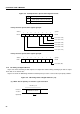
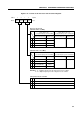
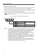
Table 5-4 shows how a built-in pull-up resistor is specified for each port pin. The built-in pull-up resistor
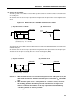
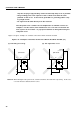
is connected by software in the format shown in Figure 5-8.
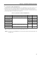
Table 5-4. Specification of Built-in Pull-Up Resistors
Port (pin name) Pull-up resistor incorporation specification method Bit of POGA Bit of POGB
Port 0 (P01-P03)
Note
Connection specification by software in 3-bit units Bit 0 —
Port 1 (P10-P13) Connection specification by software in 4-bit units Bit 1 —
Port 2 (P20-P23) Bit 2 —
Port 3 (P30-P33) Bit 3 —
Port 6 (P60-P63) Bit 6 —
Port 7 (P70-P73) Bit 7 —
Port 4 (P40-P43) Incorporation specification by mask option in 1-bit — —
Port 5 (P50-P53)
units
Port 8 (P80, P81) Connection specification by software in-2-bit units — Bit 0
Note The P00 pin cannot specify connection of a built-in pull-up resistor.
Remark The port pins of the µPD75P0016 are not connected to a pull-up resistor by mask option, and
are always open.