
User's Manual

126
µPD750008 USER'S MANUAL
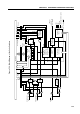
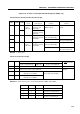
(1) Serial operation mode register 0 (CSIM)
CSIM is an 8-bit register which specifies a serial interface operation mode, serial clock, wake-up function,
and so forth. (See (1) in Section 5.6.3 for details.)
(2) Serial bus interface control register (SBIC)
SBIC is an 8-bit register consisting of bits for controlling the serial bus and flags for indicating the states
of input data from the serial bus. SBIC is used mainly in the SBI mode. (See (2) in Section 5.6.3 for
details.)
(3) Shift register (SIO)
SIO is an 8-bit register which converts 8-bit serial data to parallel data, and 8-bit parallel data to serial
data. SIO performs transfer (shift) in phase with the serial clock. Transfers operations are controlled by
writing data to SIO. (See (3) in Section 5.6.3 for details.)
(4) SO latch
SO is a latch to hold the levels of pins SO and SB0, or SI and SB1, which can be controlled directly by
software. In the SBI mode, SO is set when the eighth clock of SCK has been output. (See (2) in Section
5.6.3 for details.)
(5) Serial clock selector
The serial clock selector selects the serial clock to be used.
(6) Serial clock counter
The serial clock counter counts the serial clock to be output or input during transfer, and checks whether
8-bit data has been transferred.
(7) Slave address register (SVA) and address comparator
• In the SBI mode
SVA is used when the µPD750008 is used as a slave device. A slave sets the number assigned to
it (slave address) in SVA. The master outputs a slave address to select a particular slave.
Two data values (a slave address output from the master and the value of SVA) are compared with
each other by the address comparator. If a match is found, the slave is selected.
• In the two-wire serial I/O mode or SBI mode
SVA detects an error when data is transferred with the µPD750008 operating as the master or a slave.
(See (4) in Section 5.6.3 for details.)
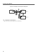
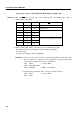
(8) INTCSI control circuit
The INTCSI control circuit controls interrupt request processing. The circuit issues an interrupt request
(INTCSI), and set an interrupt request flag (IRQCSI) in the following cases. (See Figure 6-1.)
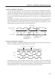
• In the three-wire or two-wire serial I/O mode
An interrupt request is issued whenever eight serial clocks are counted.
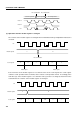
• In the SBI mode
When WUP7
Note
= 0, an interrupt request is issued whenever eight serial clocks are counted. When
WUP = 1, an interrupt request is issued when values of SVA and SIO match after an address is
received.
Note WUP: Wake-up function specification bit (bit 5 of CSIM)