
User's Manual

142
µPD750008 USER'S MANUAL
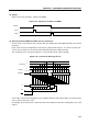
(6) Transfer start
Serial transfer is started by writing transfer data into shift register (SIO), provided that the following two
conditions are satisfied:
• The serial interface operation enable/disable specification bit (CSIE) is set to 1.
• The internal serial clock is not operating after 8-bit serial transfer, or SCK is high.
Caution Setting CSIE after writing data to the shift register does not start transfer.
When eight bits have been transferred, serial transfer automatically terminates setting the interrupt request
flag (IRQCSI).
Example To transfer the RAM data specified with the HL register to SIO, load the SIO data to the
accumulator and start serial transfer:
MOV XA,@HL ; Fetch transmit data from RAM
SEL MB15 ; or CLR1 MBE
XCH XA,SIO ; Exchange transmit data and receive data, and start transfer
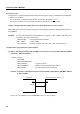
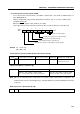
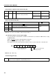
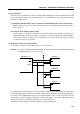
(7) Application of the three-wire serial I/O mode
(a) Data is transferred starting with the MSB on a transfer clock of 262 kHz (during 4.19-MHz
operation). (Master operation)
<Sample program>
CLR1 MBE
MOV XA,#10000010B
MOV CSIM,XA ; Set transfer mode
MOV XA,TDATA ; TDATA is transfer data storage address
MOV SIO,XA ; Set transfer data, and start transfer
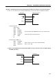
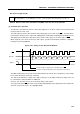
Caution A second or subsequent transfer can be started by setting data in SIO (MOV SIO,XA
or XCH XA,SIO).
In this case, the SI/SBI pin on the µPD750008 can be used as an input.
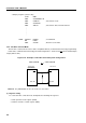
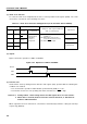
SCK
µPD750008
SO/SB0
SCK
SI
µPD7225G (LCD controller/driver), etc.