
User's Manual

185
CHAPTER 6 INTERRUPT AND TEST FUNCTIONS
6.2 TYPES OF INTERRUPT SOURCES AND VECTOR TABLES
Table 6-1 lists the types of interrupt sources, and Figure 6-2 shows vector tables.
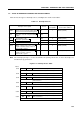
Table 6-1. Interrupt Sources
Interrupt source signal In/out
Interrupt Vectored interrupt request
priority
Note
(vector table address)
INTBT Reference time interval signal from In 1 VRQ1 (0002H)
basic interval timer/wactchdog timer
INT4 Detection of both rising and falling Out
edges
INT0
Rising/falling edge
Out 2 VRQ2 (0004H)
INT1
detection specification
Out 3 VRQ3 (0006H)
INTCSI Serial data transfer completion signal In 4 VRQ4 (0008H)
INTT0 Match signal between the count In 5 VRQ5 (000AH)
register of timer/event counter 0
and modulo register
INTT1 Match signal between the count In 6 VRQ6 (000CH)
register of timer counter 1
and modulo register
Note The interrupt priority is used to determine the priority when two or more interrupts are
simultaneously generated.
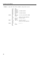
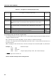
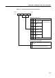
Figure 6-2. Interrupt Vector Table
MBE RBE INTBT/INT4 start address 0002H
INTBT/INT4 start address
MBE RBE INT0 start address 0004H
INT0 start address
MBE RBE INT1 start address 0006H
INT1 start address
MBE RBE INTCSI start address0008H
INTCSI start address
MBE RBE INTT0 start address 000AH
INTT0 start address
MBE RBE INTT1 start address 000CH
INTT1 start address
Address
0000H
MBE RBE Internal reset start address
Internal reset start address
(high-order 6 bits)
(low-order 8 bits)
(high-order 6 bits)
(low-order 8 bits)
(high-order 6 bits)
(low-order 8 bits)
(high-order 6 bits)
(low-order 8 bits)
(high-order 6 bits)
(low-order 8 bits)
(high-order 6 bits)
(low-order 8 bits)
(high-order 6 bits)
(low-order 8 bits)