
User's Manual

188
µPD750008 USER'S MANUAL
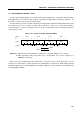
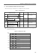
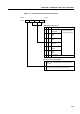
Table 6-2. Set Signals for Interrupt Request Flags
Interrupt
Set signals for interrupt request flags
Interrupt
request flag enable flag
IRQBT Set by a reference time interval signal from the basic interval timer/watchdog IEBT
timer.
IRQ4 Set by a detected rising or falling edge of an INT4/P00 pin input signal. IE4
IRQ0 Set by a detected edge of an INT0/P10 pin input signal. IE0
The detection edge is specified by the INT0 edge detection mode register
(IM0).
IRQ1 Set by a detected edge of an INT1/P11 pin input signal. IE1
The detection edge is specified by the INT1 edge detection mode register
(IM1).
IRQCSI Set by a serial data transfer completion signal for the serial interface. IECSI
IRQT0 Set by a match signal from timer/event counter 0. IET0
IRQT1 Set by a match signal from the timer counter. IET1
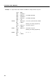
(2) Interrupt priority specification register (IPS)
The interrupt priority specification register selects an interrupt with a higher priority from multiple interrupts
using the low-order three bits.
Bit 3, interrupt master enable flag (IME), specifies whether to disable all interrupts.
The IPS is set using a 4-bit memory manipulation instruction. Bit 3 is set by an EI instruction and reset
by a DI instruction.
When changing the low-order three bits of the IPS, interrupts must be disabled (IME = 0) beforehand.
Example DI ; Disable interrupts
CLR1 MBE
MOV A,#1011B
MOV IPS,A ; Assign a higher priority to INT1, then enable interrupts.
A RESET signal clears all bits to 0.
Caution Disable interrupts before setting the IPS.