
User's Manual

2
µPD750008 USER'S MANUAL
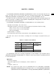
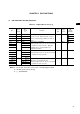
1.1 FUNCTION OVERVIEW
Item Function
Instruction execution •0.95, 1.91, 3.81, 15.3 µs (when the main system clock operates at 4.19 MHz)
time •0.67, 1.33, 2.67, 10.7 µs (when the main system clock operates at 6.0 MHz)
•122 µs (when the subsystem clock operates at 32.768 kHz)
Internal memory ROM 4096 x 8 bits (µPD750004)
6144 x 8 bits (µPD750006)
8192 x 8 bits (µPD750008)
16384 x 8 bits (µPD75P0016)
RAM 512 x 4 bits
General register •When operating in 4 bits: 8 x 4 banks
•When operating in 8 bits: 4 x 4 banks
I/O port 34 8 CMOS input pins Can incorporate 25 pull-up resistors
18 CMOS I/O pins
that are specified with the software.
Four pins can directly drive
the LED.
8 N-ch open-drain I/O pins Can withstand 13 V.
Eight pins can directly drive Can incorporate pull-up resistors that
the LED. are specified with the mask option.
Note
Timer 4 •Timer/event counter: 1 channel
•Timer counter: 1 channel
•Basic interval timer/watchdog timer: 1 channel
•Clock timer: 1 channel
Serial interface •Three-wire serial I/O mode (switchable between the start LSB and the start MSB)
•Two-wire serial I/O mode
•SBI mode
Bit sequential buffer 16 bits
Clock output •F, 524 kHz, 262 kHz, 65.5 kHz (when the main system clock operates at 4.19 MHz)
•F, 750 kHz, 375 kHz, 93.7 kHz (when the main system clock operates at 6.0 MHz)
Vectored interrupt External: 3,Internal: 4
Test input External: 1,Internal: 1
System clock oscillator •Ceramic or crystal oscillator for the main system clock
•Crystal oscillator for the subsystem clock
Standby function STOP/HALT mode
Operating ambient T
A
=
–40°C to +85°C
temperature
Supply voltage V
DD
=
2.2 to 5.5 V
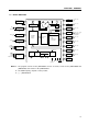
Package 42-pin plastic shrink DIP (600 mil)
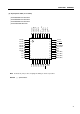
44-pin plastic QFP (10 x 10 mm)
NoteThe N-ch open-drain I/O port pins of the µPD75P0016 are not connected to pull-up resistors by mask
option, and are always open.
*
*