
User's Manual


264
µPD750008 USER'S MANUAL
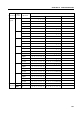
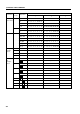
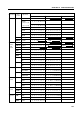
11.4 FUNCTIONS AND APPLICATIONS OF THE INSTRUCTIONS
This section explains functions and applications of the instructions. For the µPD750004, µPD750006,
µPD750008, and µPD75P0016, usable instructions and their functions in Mk I mode are different from those
in Mk II mode. Read the following explanation.
How to read
Can be used in both Mk I mode and Mk II mode for the µPD750004, µPD750006, µPD750008, and
µPD75P0016
I Can be used in only Mk I mode for the µPD750004, µPD750006, µPD750008, and µPD75P0016
II Can be used in only Mk II mode for the µPD750004, µPD750006, µPD750008, and µPD75P0016
I/II Can be used in both Mk I mode and Mk II mode for the µPD750004, µPD750006, µPD750008, and
µPD75P0016. However, Mk I mode is different from Mk II mode in the functions. Read the
explanation of [Mk I mode] for Mk I mode and the explanation of [Mk II mode] for Mk II mode, as
required.
Remark "Function" in this section is applicable to the µPD750006 and µPD750008 whose program
counters consist of 13 bits each. This is also applicable to the µPD750004 whose program
counter consists of 12 bits and the µPD75P0016 whose program counter consists of 14 bits,
however.
11.4.1 Transfer Instructions
MOV A,#n4
Function: A <– n4 n4 = I
3-0
: 0-FH
Transfers the 4-bit immediate data n4 to the A register (4-bit accumulator).
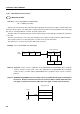
The string effect (group A) can be utilized. When MOV A, #n4 and/or MOV XA, #n8 instructions are located
contiguously, the string instructions following an executed instruction are processed as NOP instructions.
Examples 1. The data 0BH is set in the accumulator.
MOV A,#0BH
2. Data to be output to port 3 is selected from 0 to 2.
A0: MOV A,#0
A1: MOV A,#1
A2: MOV A,#2
OUT PORT3,A