
User's Manual

12
µPD750008 USER'S MANUAL
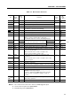
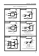
2.2 PIN FUNCTIONS
2.2.1 P00-P03 (PORT0) : Input Pins Used Also for INT4, SCK, SO/SB0 and SI/SB1
P10-P13 (PORT1) : Input Pins Used Also for INT0-INT2, and TI0
These are the input pins of the 4-bit input ports: Ports 0 and 1.
Ports 0 and 1 function as input ports, and also have the functions described below.
(1) Port 0 : Vectored interrupt input (INT4)
Serial interface I/O (SCK, SO/SB0, SI/SB1)
(2) Port 1 : Vectored interrupt input (INT0, INT1)
Edge detection test input (INT2)
External event pulse input (TI0) for timer/event counter
Input is always enabled for each pin of ports 0 and 1 regardless of the operation status of the other function
of the pin.
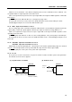
Schmitt-triggered inputs are used for the input pin of port 0 and pins of port 1 to prevent malfunction due
to noise. In addition, a noise eliminator is provided for P10. (See (3) of Section 6.3.)
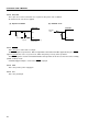
Port 0 can be connected with built-in pull-up resistors in units of 3 bits (P01 to P03) by software. Port 1
can be connected with built-in pull-up resistors in units of 4 bits (P10 to P13) by software. This is done by
manipulating pull-up resistor specification register group A (POGA).
A RESET signal input places these pins in the input port mode.