USER'S MANUAL µPD75402A 4-BIT SINGLE-CHIP MICROCOMPUTER µPD75402A µPD75P402 © NEC Corporation 1989 Document No. IEU1270C (O. D. No.
MS-DOS is a trademark of Microsoft Corporation. PC/AT, PC DOS are trademarks of IBM Corporation. The information in this document is subject to change without notice. No part of this document may be copied or reproduced in any form or by any means without the prior written consent of NEC Corporation. NEC Corporation assumes no responsibility for any errors which may appear in this document.
Major Revisions in This Version Section P.117 P.179 to 181 Description Amendment: Fig. 5-52 “Data Transmission from Slave Device to Master Device” Change: Appendix B “Development Tools” The mark ★ shows main revised points.
PREFACE USER This manual is intended for user engineers who wish to understand the µPD75402A’s, 75P402’s functions and design an application system using them. OBJECTIVE The objective of this manual is for the user to understand the µPD75402A’s, 75P402’s hardware functions shown below. COMPOSITION This manual is composed roughly of the following contents.
Related Documentation Device Related Documents Document Name Document Number User's Manual IEU-644 Instruction Application Table IEM-5504 Application Note IEA-638 75X Series Selection Guide IF-151 Development Tool Related Documents Software Hardware Document Name Document Number IE-75000-R/IE-75001-R User's Manual EEU-846 IE-75000-R-EM User's Manual EEU-673 EP-75402C-R User's Manual EEU-701 EP-75402GB-R User's Manual EEU-702 PG-1500 User's Manual EEU-651 RA75X Assembler Package l
CONTENTS CHAPTER 1. GENERAL ............................................................................................................................... 1 1.1 1.2 OUTLINE OF FUNCTIONS . .......................................................................................................................... ORDERING INFORMATION AND QUALITY GRADE .................................................................................. 2 3 1.3 DIFFERENCES BETWEEN µPD75402A AND µPD75402, 75P402 .............
CHAPTER 4. INTERNAL CPU FUNCTIONS ........................................................................................... 31 4.1 PROGRAM COUNTER (PC) ........................................................................................................................... 31 4.2 PROGRAM MEMORY (ROM) . ..................................................................................................................... 32 4.3 4.4 DATA MEMORY (RAM) ................................................
6.5 6.6 MACHINE CYCLES BEFORE INTERRUPT SERVICING .............................................................................. 135 INTERRUPT APPLICATIONS ........................................................................................................................ 137 CHAPTER 7. STANDBY FUNCTION . ...................................................................................................... 141 7.1 7.2 STANDBY MODE SETTING AND OPERATION STATES .........................................
CONTENTS OF FIGURES Fig. No Title Page 3-1 Static RAM Address Updating Method ............................................................................................. 25 4-1 Program Counter Configuration ......................................................................................................... 31 4-2 Program Memory Map ........................................................................................................................ 32 4-3 4-4 Data Memory Map .............
Fig. No. Title Page 5-32 Example of SBI Serial Bus System Configuration ........................................................................... 93 5-33 5-34 SBI Transfer Timing ............................................................................................................................. 95 Bus Release Signal ............................................................................................................................... 96 5-35 Command Signal ........................
CONTENTS OF TABLES Table No. Title Page 1-1 Differences Between µPD75402A and µPD75402, 75P402 ................................................................. 4 2-1 2-2 Port Pin List ........................................................................................................................................... 11 List of Pins Other than Port Pins ........................................................................................................
CHAPTER 1. GENERAL CHAPTER 1. GENERAL The µPD75402A, 75P402 is a CMOS 4-bit single-chip microcomputer adopting the 75X architecture. With its builtin NEC standard serial bus interface (SBI), it is suitable as a slave microcomputer in a multiprocessor system configuration using the 75X, 78K series as the host microcomputer. The µPD75402A has shortened the conventional µPD75402’s minimum instruction execution time to 0.95 µs. The µ PD75P402 is also capable of high-speed processing.
CHAPTER 1. GENERAL 1.1 OUTLINE OF FUNCTIONS Item Number of basic instructions 37 Instruction execution time • 0.95 µs, 1.91 µs, 15.3 µs (at 4.
CHAPTER 1. GENERAL 1.
CHAPTER 1. GENERAL 1.3 DIFFERENCES BETWEEN µPD75402A AND µPD75402, 75P402 Table 1-1 shows the differences between the µPD75402A and the µPD75402, 75P402. Otherwise the µ PD75402A and the µ PD75402, 75P402 have the same functions and are pin-compatible. Table 1-1 Differences Between µPD75402A and µPD75402, 75P402 Item ROM configuration µPD75402A µPD75402 Mask ROM 0.95, 1.91, 15.3 µs (at 4.19 MHz operation) Instruction execution time Port 5’s pull-up resistor 1.91, 15.3 µs* (at 4.
1.4 BLOCK DIAGRAM BASIC INTERVAL TIMER ALU PROGRAM COUNTER(11) CY PORT0 4 P00-P03 PORT1 2 P10, P12 PORT2 4 P20-P23 PORT3 4 P30-P33 PORT5 4 P50-P53 PORT6 4 P60-P63 SP (5) INTBT SO/SB0 SERIAL INTERFACE SCK INTCSI INT0 INT2 INTERRUPT CONTROL ROM (PROM) PROGRAM MEMORY GENERAL REG. DECODE AND CONTROL 1920 × 8 bits fxx/2 CLOCK OUTPUT CONTROL N CLOCK DIVIDER PCL Remarks RAM DATA MEMORY 64 x 4 bits Parentheses for the µPD75P402.
CHAPTER 1. GENERAL 1.5 PIN CONFIGURATION 1.5.
CHAPTER 1.
CHAPTER 1. GENERAL 1.5.
CHAPTER 1.
CHAPTER 2. PIN FUNCTIONS CHAPTER 2. PIN FUNCTIONS The µPD75402A operates by the pin functions in the normal operating mode. For the µPD75P402’s pin functions, the 2 modes of the normal operating mode (µPD75402A mode) and the PROM mode are available. The operating mode switches according to the VPP pin level as shown in the table below. VPP Low level (GND potential) Operating Mode Normal operating mode High level (+5 V) PROM read mode PROM mode High level (+12.
CHAPTER 2. PIN FUNCTIONS µ PD75402A PIN FUNCTION LIST 2.1 2.1.1 Port Pin List Table 2-1 Port Pin List Pin Name Input/Output Functions Dual-Function Pin A 4-bit input port (Port 0). P00 Input P01 Input/output SCK P02 Input/output SO/SB0 P03 Input SI P10 Input INT0 For P01 to P03, it is designatable to build in the pull-up resistor by software in 3-bit units. A 2-bit input port (Port 1). P10 is built in with the noise eliminator by the sampling clock.
CHAPTER 2. PIN FUNCTIONS 2.1.2 List of Pins Other Than Port Pins Table 2-2 List of Pins Other than Port Pins Pin Name Input/Output Dual-Function Pin INT0 Input P10 Functions An edge-detected vectored interrupt request input pin (detected edge selectable by mode register). Built in with the noise eliminator by the sampling clock. INT2 Input P12 An edge detected external test input pin (rising edge detection). SI Input P03 A serial data input pin.
CHAPTER 2. PIN FUNCTIONS 2.2 2.2.1 NORMAL OPERATING MODE P00 to P03 (Port 0) ..... SCK, SO/SB0, SI Dual-Function Input P10, P12 (Port 1) ..... INT0, INT2 Dual-Function Input P00 to P03 are the 4-bit input port: Port 0’s input pins. P10 and P12 are the 2-bit input port: Port 1’s input pins. Ports 0 and 1 also have the functions of the various control signal pins shown in Table 2-1 in addition to the functions as input ports.
CHAPTER 2. PIN FUNCTIONS 2.2.2 P20 P30 P50 P60 to to to to P23 P33 P53 P63 (Port (Port (Port (Port 2) 3) 5) 6) ..... ..... ..... ..... PCL Dual-Function 3-Stae Input/Otput 3-State Input/Output N-ch Open Drain Middle-Voltage (10 V) Input/Output 3-State Input/Output The 4-bit input/output port with the output latch: Port 2’s, 3’s, 5’s, 6’s 4-bit input/output pins. Port 2 also shares the programmable clock output (PCL) function with P22 in addition to having the input/output port function.
CHAPTER 2. PIN FUNCTIONS 2.2.7 X1, X2 (Crystal) The built-in clock oscillation crystal/ceramic input. It is also possible to supply the clock from the exterior. (a) Crystal/Ceramic Oscillation (b) External Clock V DD µ PD75402A V DD X1 µ PD75402A External Clock X1 µ PD74HC04 X2 Crystal Resonator or Ceramic Oscillator (Standard 4.194304 MHz) 2.2.8 X2 RESET (Reset) A low level active system reset input pin. It has Schmitt-triggered input and is built in with the noise eliminator by analog delay.
CHAPTER 2. PIN FUNCTIONS 2.3 PROM MODE The PROM mode is designatable in the µ PD75P402 alone. 2.3.1 A0 to A14 (Address) ..... Input A 15-bit address input pin at PROM write/verify, read. As the PROM built into the µPD75P402 has 2K bytes, it is addressed by the low-order 11 bits (A0 to A10). A11 to A14 should be fixed to the low level. 2.3.2 O0 to O7 (Data) ..... Input/Output An 8-bit data input/output pin at PROM write/verify, read. 2.3.3 CE (Chip Enable) ..... Input A chip enable signal input pin.
CHAPTER 2. PIN FUNCTIONS 2.4 PIN INPUT/OUTPUT CIRCUITS The input/output circuit of each pin is shown below in a partly simplified format. Table 2-4 Pin Input/output Types Input/Output Type Pin µPD75402A P00 µPD75P402 B P01/SCK F-A P02/SO/SB0 F-B P03/SI B-C P10/INT0 B P12/INT2 B-C P20, P21, P23 E-B P22/PCL P30 to P33 P50 to P53 P60 to P63 RESET Remarks A circle E-B M M-A E-B B indicates Schmitt-triggered input.
CHAPTER 2. PIN FUNCTIONS Type A (for Types E - B) Type D (for Type E - B, F - A, Y - D) VDD VDD data P-ch P-ch IN OUT N-ch output disable An input buffer of the CMOS standard N-ch Push-pull output that can be turned output high impedance (P-ch, N-ch, both off) Type E - B Type B VDD P.U.R. P.U.R. enable P-ch data IN/OUT IN output disable Type D Type A Schmitt-triggered input having hysteresis characteristics Type B - C P. U. R : Pull-Up Resistor Type F - A VDD P.U.R. VDD P.U.R.
CHAPTER 2. PIN FUNCTIONS Type F - B Type M - A VDD P.U.R. P.U.R. enable output disable (P) IN/OUT P-ch VDD data P-ch IN/OUT data output disable output disable N-ch (+10 V Withstand Voltage) N-ch output disable (N) Middle-High Voltage Input Buffer (+10 V Withstand Voltage) P. U. R : Pull-Up Resistor Type M VDD P.U.R (Mask Option) data output disable IN/OUT N-ch (+10 V Withstand Voltage) Middle-High Voltage Input Buffer (+10 V Withstand Voltage) P. U.
CHAPTER 2. PIN FUNCTIONS 2.5 UNUSED PIN TREATMENT Pin Recommended Connection Method P00 Connect to V SS. P01 to P03 • With pull-up resistor Connect to VDD. P10 and P12 • Without pull-up resistor Connect to VSS or VDD. P20 to P23 • With pull-up resistor Input status: Connect to VDD. P30 to P33 Output status: Leave open. P50 to P53 • Without pull-up resistor Input status: Connect to VSS to VDD. P60 to P63 Output status: Leave open. Leave open or connect directly to VSS.* NC * 2.
CHAPTER 3. FEATURES OF ARCHITECTURE AND MEMORY MAP CHAPTER 3. FEATURES OF ARCHITECTURE AND MEMORY MAP The µPD75402A’s architecture is a subset of the 75X architecture. Its features are outlined below. 3.1 3.1.1 DATA MEMORY BANK CONFIGURATION AND ADDRESSING MODES Data Memory Bank Configuration The µPD75402A’s data memory space has a bank configuration. Addresses 000H to 03FH of Bank 0 are a data area as shown in Table 3-1 and are built in with a static RAM (64 × 4 bits).
CHAPTER 3. FEATURES OF ARCHITECTURE AND MEMORY MAP Table 3-1 Data Memory Configuration and Address Range in Each Addressing Mode Addressing Mode Adress 000H 003H Data Memory General Register Area Data Memory Static RAM (Memory Bank 0) 020H Stack Area 03FH Not built in. F80H FB0H FBFH FF0H FFFH 22 Peripheral Hardware Area (Memory Bank 15) mem mem. bit @ HL Stack Addressing fmem.
CHAPTER 3. FEATURES OF ARCHITECTURE AND MEMORY MAP Table 3-2 Addressing Mode List Addressing Mode 1-bit direct Notation mem. bit Specified Address The bit indicated by bit of the address indicated by mem. However: Memory bank 0 is accessed if mem = 00H to 3FH. addressing Memory bank 15 is accessed if mem = 80H to FFH. 4-bit direct mem The address indicated by mem. However: Memory bank 0 is accessed if mem = 00H to 3FH. addressing Memory bank 15 is accessed if mem = 80H to FFH.
CHAPTER 3. FEATURES OF ARCHITECTURE AND MEMORY MAP 3.1.2 Data Memory Addressing Modes In the µPD75402A, the 6 types of addressing modes listed on Table 3-2 are available for the data memory space for efficient addressing per the bit length of the data to be processed. Also in the µPD75402A, the memory bank to be accessed is fixed by the addressing mode unlike in other products of the 75X series. So programming is possible without caring about memory bank switching. (1) 1-bit direct addressing (mem.
CHAPTER 3. FEATURES OF ARCHITECTURE AND MEMORY MAP (3) 8-bit direct addressing (mem) An addressing mode to specify the whole data memory space directly by the instruction’s operand per 8 bits. The specified memory bank (MB) is MB = 0 if the address specified by the operand is 00H to 3EH and MB = 15 if it is 80H to FEH. Consequently, both the static RAM area of 000H to 03FH and the peripheral hardware area of FF0H to FFFH are addressable.
CHAPTER 3. FEATURES OF ARCHITECTURE AND MEMORY MAP (5) Specific address bit manipulation addressing (fmem. bit) An addressing mode to specify each bit of the input/output port, interrupt, etc. flag, etc. of the peripheral hardware directly by the instruction’s operand. Consequently, the data memory addresses to which this addressing mode is applied are FB0H to FBFH, FF0H to FFFH. While the 1-bit direct addressing mode (mem.
CHAPTER 3. FEATURES OF ARCHITECTURE AND MEMORY MAP (6) Stack addressing This addressing mode is for the saving/restoring operation during the interrupting process, subroutine process. The data memory is addressed indirectly according to the content of the stack pointer (SP : 8 bits). The memory bank (MB) addressed in this addressing mode is fixed to 0. Also as the stack pointer’s high-order 3 bits are fixed to 001, the addressable area is limited to 020H to 03FH.
CHAPTER 3. FEATURES OF ARCHITECTURE AND MEMORY MAP 3.2 MEMORY-MAPPED I/O The µPD75402A adopts memory-mapped I/O to map such peripheral hardware as the input/output port, serial interface at addresses F80H to FFFH in the data memory space shown in Table 3-1. As a result, there is no special instruction to control the peripheral hardware; the peripheral hardware is controlled wholly by memory manipulation instructions (some hardware control mnemonics are available to make the program easy to understand).
CHAPTER 3. FEATURES OF ARCHITECTURE AND MEMORY MAP Table 3-4 µ PD75402A I/O Map (1/2) No. of Manipulatable Addressing Hardware Name (Symbol) Address b3 b2 b1 b0 1 Bit 4 Bits 8 Bits Bit Manipulation Remarks Bit 0 is fixed to 0. F80H Stack pointer (SP) F85H W 11 must always be written in bit 1, 0. W Basic interval timer mode register (BTM) F86H R Basic interval timer (BT) Manipulation by EI.
CHAPTER 3. FEATURES OF ARCHITECTURE AND MEMORY MAP Table 3-4 µ PD75402A I/O Map (2/2) No. of Manipulatable Addressing Hardware Name (Symbol) Address b3 FE0H b2 b1 b0 1 Bit 4 Bits 8 Bits Bit Manipulation Serial operation mode register (CSIM) W FE1H FE2H CSIE COI WUP 0 CMDD RELD CMDT RELT *1 mem. bit *2 mem. bit SBI control register (SBIC) FE3H Remarks BSYE ACKD ACKE ACKT *3 0 must always be written in bit 0. Bit manipulation only is possible for all the bits.
CHAPTER 4. INTERNAL CPU FUNCTIONS CHAPTER 4. INTERNAL CPU FUNCTIONS 4.1 PROGRAM COUNTER (PC) ..... 11 BITS An 11-bit binary counter to hold the program memory address information. Fig. 4-1 Program Counter Configuration PC10 PC9 PC8 PC7 PC6 PC5 PC4 PC3 PC2 PC1 PC0 The program counter operates as follows. • Normal operation The content is incremented automatically according to the number of bytes of the instruction every time one is executed.
CHAPTER 4. INTERNAL CPU FUNCTIONS 4.2 PROGRAM MEMORY (ROM) ..... 1,920 WORDS × 8 BITS A mask programmable ROM of a 1,920-word × 8-bit configuration. It stores the program, table data, etc. The program memory is addressed by the program counter. It is also possible to read the table data in the ROM by the table refer instruction (MOVT). It is possible to branch to any area of the program memory by the branch instruction, subroutine call instruction (see Fig. 4-2).
CHAPTER 4. INTERNAL CPU FUNCTIONS 4.3 DATA MEMORY (RAM) The data memory consists of the data and peripheral hardware areas as shown in Fig. 4-3. Fig. 4-3 Data Memory Map Data Memory General Register Area Data Area Static RAM (64 × 4) 000H 003H 004H Memory Bank (4 × 4) Bank 0 (64 × 4) 020H (32 × 4) Stack Area 03FH Not built in. F80H Peripheral Hardware Area 128 × 4 Bank 15 FFFH (1) Data area The µPD75402A’s data area consists of the static RAM (64 words × 4 bits).
CHAPTER 4. INTERNAL CPU FUNCTIONS (2) Peripheral hardware area The peripheral hardware area is mapped to memory bank 15’s addresses F80H to FFFH. The operation is performed by the memory manipulation instruction just as in the static RAM. In the peripheral hardware, however, the operable bit unit differs from one address to another. It is impossible to access an address to which the peripheral hardware is not assigned since the data memory is not built in. (See Table 3-4 “µ PD75402A I/O Map".
CHAPTER 4. INTERNAL CPU FUNCTIONS 4.4 GENERAL REGISTER ..... 4 × 4 BITS The general register is assigned to a specific address of the data memory. There are four 4-bit registers (H, L, X, A). While each general register is operated per 4 bits, HL and XA make up register pairs, each of which is operated per 8 bits. The HL register pair is available as the data pointer to indirectly address the memory.
CHAPTER 4. INTERNAL CPU FUNCTIONS 4.5 ACCUMULATOR In the µPD75402A, the A register and the XA register pair function as accumulators. The 4-bit data process instruction is executed mainly by the A register and the 8-bit data process instruction is executed mainly by the XA register pair. In the bit manipulation instruction, the carry flag (CY) functions as the bit accumulator. Fig.
CHAPTER 4. INTERNAL CPU FUNCTIONS 4.6 STACK POINTER (SP) ..... 8 BITS The µPD75402A uses a static RAM as the stack memory (LIFO format). The 8-bit register holding the top address information of such a stack memory area is the stack pointer (SP). Fig. 4-7 shows its format. As the SP’s high-order 3 bits are fixed to 001, the stack area is at the static RAM’s addresses 020H to 03FH. The SP is decremented before write (save) in the stack memory and is incremented after read (restore) from the stack memory.
CHAPTER 4. INTERNAL CPU FUNCTIONS Fig. 4-8 Data Saved to Stack Memory PUSH Instruction CALLF Instruction Interrupt Stack Stack Stack SP - 4 0 SP - 3 0 PC10 - PC8 0 0 0 SP - 6 0 SP - 5 0 PC10 - PC8 0 0 SP - 2 Register Pair Low Order SP - 2 PC3 - PC0 SP - 4 PC3 - PC0 SP - 1 Register Pair High Order SP - 1 PC7 - PC4 SP - 3 PC7 - PC4 SP SP SP - 2 SP - 1 0 0 IST0 0 0 PSW CY SK2 SK1 SK0 SP Fig.
CHAPTER 4. INTERNAL CPU FUNCTIONS 4.7 PROGRAM STATUS WORD (PSW) ..... 8 BITS The program status word (PSW) consists of various flags concerning closely the processor operation. Fig. 4-10 shows its configuration. Saved to the stack memory per 8 bits at the interrupt acceptance and restored from the stack memory per 8 bits at the RETI instruction execution (see Figs. 4-8 and 4-9). Fig.
CHAPTER 4. INTERNAL CPU FUNCTIONS Example Take AND of bit 3 at address 3FH and P33 and set the result in CY. SET1 CY ; CY← 1 SKT 3FH. 3 ; Skip if bit 3 at address 3FH is 1 CLR1 AND1 CY CY, PORT 3. 3 ; CY← 0 ; CY← CY∧ P33 (2) Skip flag (SK2, SK1, SK0) The skip flag is a flag to store the skip status. It is set/reset automatically as the CPU executes an instruction. It is impossible for the user to operate it directly by the program.
CHAPTER 5. PERIPHERAL HARDWARE FUNCTIONS CHAPTER 5. PERIPHERAL HARDWARE FUNCTIONS 5.1 DIGITAL INPUT/OUTPUT PORTS The µPD75402A has the following digital input/output ports on chip: Ports 0 through 3, 5 and 6. The µPD75402A uses memory mapped I/O, and all input/output ports are mapped onto data memory space. All data memory handling instructions can be used on all of the ports, and a wide variety of bit operations can be performed in addition to 4-bit input/output.
CHAPTER 5. PERIPHERAL HARDWARE FUNCTIONS 5.1.1 Digital Input/Output Port Types, Characteristics and Configuration The different types of digital input/output ports are shown in Table 5-1, and the configuration of each port is shown in Figs. 5-2, 5-3, 5-4 and 5-5. Table 5-1 Digital Input/Output Port Types and Characteristics Port (Symbol) Function PORT0 PORT1 4-bit input Can always be read or tested regardless of dual-function pin operating mode.
CHAPTER 5. PERIPHERAL HARDWARE FUNCTIONS Fig.
CHAPTER 5. PERIPHERAL HARDWARE FUNCTIONS Fig.
CHAPTER 5. PERIPHERAL HARDWARE FUNCTIONS Fig. 5-4 Configuration of Ports 2 and 6 VDD Pull-up Resistors POGA Bit m P-ch POm Input Buffer PMm = 0 PMm = 1 Pm0 Output Latch Internal Bus M P X Pm1 Pm2 Pm3 PM2/ PM60 to 63 * Output Buffer PMGB Bit 2, PMGA bits 4 to 7 * Input/output mode specification is performed by bit 2 (PM2) of PMGB for port 2 and by bits 4 to 7 (PM60 to 63) of PMGA for port 6.
CHAPTER 5. PERIPHERAL HARDWARE FUNCTIONS Fig. 5-5 Configuration of Port 5 VDD Pull-Up Resistors (Mask Option; µPD75402A Only) Input Buffer PM5=0 Internal Bus M P X PM5=1 Output Latch P50 P51 P52 P53 N-ch Open-Drain Output Buffer PM5 PMGB Bit 5 5.1.2 Input/Output Mode Setting The input/output mode for each input/output port is set by a port mode register as shown in Fig. 5-6. For port 3, input/output can be specified bit by bit by port mode register group A (PMGA).
CHAPTER 5. PERIPHERAL HARDWARE FUNCTIONS Fig.
CHAPTER 5. PERIPHERAL HARDWARE FUNCTIONS (1) Bit handling instructions Direct addressing of specific address bits (fmem.bit) can be used on all digital input/output ports. Example To OR P50 and P31 and output the result to P61. SET1 CY ; CY ← 1 AND1 CY, PORT5.0 ; CY ← CY OR1 CY, PORT3.1 ; CY ← CY CY CLRP PORT6.1 ; P61 ← 1 PORT6.
CHAPTER 5. PERIPHERAL HARDWARE FUNCTIONS 5.1.4 Digital Input/Output Port Operations Port and port pin operations when a data memory handling instruction is executed for a digital input/output port differ according to the input/output mode setting (see Table 5-3). This is because, as can be seen from the input/ output port configurations, data fetched onto the internal bus is treated as pin data in input mode and as output latch data in output mode.
CHAPTER 5. PERIPHERAL HARDWARE FUNCTIONS Table 5-3 Operations with Input/Output Port Handling Instructions Port and Individual Pin Operations Instruction Executed Input Mode Tests pin data. Tests output latch data. AND1 CY, PORTn.bit OR1 CY, PORTn.bit XOR1 CY, PORTn.bit Operation between pin data and CY Operation between output latch data and CY IN MOV A, PORTn A, PORTn Transfers pin data to accumulator. Transfers output latch data to accumulator.
CHAPTER 5. PERIPHERAL HARDWARE FUNCTIONS 5.1.5 Internal Pull-up Resistors The µPD75402A can incorporate internal pull-up resistors for all port pins except P00 and P10. The µPD75P402 can incorporate internal pull-up resistors for all port pins except P00, P10, and P50 through P53. As shown in Table 5-4, internal pull-up resistors can be specified by software or by a mask option (although specification by mask option is not possible on the µPD75P402).
CHAPTER 5. PERIPHERAL HARDWARE FUNCTIONS Fig.
CHAPTER 5. PERIPHERAL HARDWARE FUNCTIONS 5.1.6 Digital Input/Output Port Input/Output Timing The timing for outputting data to the output latch and fetching pin data or output latch data onto the internal bus is shown in Fig. 5-9. Fig.
CHAPTER 5. PERIPHERAL HARDWARE FUNCTIONS 5.2 CLOCK GENERATION CIRCUIT The clock generation circuit supplies various clocks to the CPU and peripheral hardware, and controls the operating mode of the CPU. 5.2.1 Clock Generation Circuit Configuration The configuration of the clock generation circuit is shown in Fig. 5-10. ★ Fig.
CHAPTER 5. PERIPHERAL HARDWARE FUNCTIONS 5.2.2 Clock Generation Circuit Function and Operaion The clock generation circuit generates the CPU clock ( Φ ) and various clocks for supply to peripheral hardware, and controls the CPU operating mode, such as standby mode etc. Clock generation circuit operation is determined by the processor clock control register (PCC). Upon RESET input, the PCC is cleared to 0000 and the µPD75402A operates in low-speed mode (15.3 µs: when operating at 4.19 MHz).
CHAPTER 5. PERIPHERAL HARDWARE FUNCTIONS Fig. 5-11 Processor Clock Control Register Format Address FB3H 3 2 1 0 PCC3 PCC2 PCC1 PCC0 Symbol PCC CPU clock selection bits when fXX ≤ 4.19 MHz ( ) : When fXX = 4.19 MHz CPU Clock Frequency 1 Machine Cycle 0 0 Φ Output = fXX/64 (65.5 kHz) 15.3 µs 0 1 Setting prohibited – 1 0 Φ = f XX/8 (524 kHz) 19.1 µs 1 1 Φ = f XX/4 (1.05 MHz) 0.95 µs When 4.19 MHz < fXX ≤ 5.0 MHz ( ) : When fXX = 4.
CHAPTER 5. PERIPHERAL HARDWARE FUNCTIONS (2) System clock oscillation circuit The system clock oscillation circuit oscillates by means of a crystal resonator or ceramic resonator connected to the X1 and X2 pins (standard: 4.194304 MHz). An external clock can also be input. Fig. 5-12 System Clock Oscillation Circuit External Circuitry (a) Crystal/ceramic oscillation (b) External clock µPD75402A VDD µPD75402A External Clock X1 VDD X1 X2 X2 Crystal Resonator or Ceramic Oscillator Note (Standard 4.
CHAPTER 5. PERIPHERAL HARDWARE FUNCTIONS Fig. 5-13 Example of Poor Resonator Connection Circuit (2/2) (c) Signal line close to varyin high current (d) Current flows an oscillator power supply line. (potentials at A, B and C fluctuate.) µPD75402A VDD µPD75402A VDD X1 VDD PORTn X2 X1 X2 C B High current (e) Signal is picked up.
CHAPTER 5. PERIPHERAL HARDWARE FUNCTIONS 5.2.3 CPU Clock Setting The CPU clock Φ is the clock supplied to the µPD75402A’s internal CPU, and the reciprocal of this clock is the minimum instruction execution time (defined in this manual as 1 machine cycle). On the µPD75402A, Φ can be switched in 3 steps by setting the PCC. In other words, with the same system clock oscillator frequency fXX, the minimum instruction execution time can be changed in 3 steps.
CHAPTER 5. PERIPHERAL HARDWARE FUNCTIONS As the PCC is set in 0 by RESET input, Φ is reset-started at the slowest speed (state in which the operating voltage range is wide). For this reason, in a system with a slow supply voltage rise (such as a system with a high- capacitance capacitor connected), correct operation is possible even when an adequate supply voltage cannot be attained after a power-on reset. Fig.
CHAPTER 5. PERIPHERAL HARDWARE FUNCTIONS 5.2.4 Differences Between µPD75402A and µPD75402 Part of the clock generation circuit differs between the µPD75402A and the µPD75402. The µPD75402 does not include the sections enclosed in dotted lines. Fig.
CHAPTER 5. PERIPHERAL HARDWARE FUNCTIONS Next, the processor clock control register (PCC) of the µPD75402 is shown below. Setting of bit 1 of the PCC is performed by a 4-bit memory handling instruction. At this time, ensure that bits 3, 2 and 0 are reset to “0” so that the pattern “00 × 0” is written. Fig. 5-17 µPD75402 Processor Clock Control Register Format Address FB3H 3 2 1 PCC3 PCC2 PCC1 0 Symbol 0 PCC CPU clock selection bits when fXX ≤ 4.19 MHz ( ) : When fXX = 4.
CHAPTER 5. PERIPHERAL HARDWARE FUNCTIONS 5.3 CLOCK OUTPUT CIRCUIT The clock output circuit outputs clock pulses from the P22/PCL pin, and is used to supply clock pulses to peripheral LSIs, etc. 5.3.1 Clock Output Circuit Configuration The configuration of the clock output circuit is shown in Fig. 5-18. Fig. 5-18 Clock Output Circuit Configuration From Clock Generation Circuit Φ Output Buffer Selector fXX/2 6 P22/PCL PORT2.
CHAPTER 5. PERIPHERAL HARDWARE FUNCTIONS 5.3.2 Clock Output Mode Register (CLOM) CLOM is a 4-bit register used to control clock output. CLOM is set by a 4-bit memory handling instruction. Bit handling instructions cannot be used. Also, this register cannot be read. RESET input clears CLOM to zero and selects the clock output disabled state. Fig. 5-19 Clock Output Mode Register Format Address 3 2 FD0H CLOM3 0 1 0 CLOM1 CLOM0 Symbol CLOM Clock output frequency selection bits ( ) : When fXX = 4.
CHAPTER 5. PERIPHERAL HARDWARE FUNCTIONS 5.3.3 Clock Output Procedure Clock pulse output is performed by the following procedure. (i) Set the clock output mode register. (ii) Write 0 to the P22 output latch. (iii) Set the port 2 input/output mode to output. This procedure may be reversed depending on the treatment of P22/PCL prior to clock output. Example 1. To output a 65.5 kHz (at 4.19 MHz operation) clock from the PCL/P22 pin. (The PCL/P22 pin outputs the clock from the high-impedance state.
CHAPTER 5. PERIPHERAL HARDWARE FUNCTIONS 5.4 BASIC INTERVAL TIMER The µPD75402A is equipped with an 8-bit basic interval timer which has the following functions: (a) Standard time generation (2 different time intervals) (b) Reading counter contents This basic interval timer can also be used as a watchdog timer for the detection of inadvertent program looping. 5.4.1 Basic Interval Timer Configuration The configuration of the basic interval timer is shown in Fig. 5-21. Fig.
CHAPTER 5. PERIPHERAL HARDWARE FUNCTIONS 5.4.2 Basic Intercal Timer Mode Register (BTM) BTM is a 4-bit register which controls the operation of the basic interval timer. BTM is set by a 4-bit memory handling instruction. Bit operations are not possible. Example To set the interrupt generation interval to 1.95 ms (4.19 MHz). MOV A, #1111B MOV BTM.
CHAPTER 5. PERIPHERAL HARDWARE FUNCTIONS 5.4.3 Basic Interval Timer Operation The basic interval timer (BT) is constantly incremented by the clock from the clock generation circuit, and sets the interrupt request flag (IRQBT) when it overflows. The BT count operation cannot be stopped. Either of two times can be selected as the interrupt generation interval by setting the BTM (Fig. 5-22).
CHAPTER 5. PERIPHERAL HARDWARE FUNCTIONS 5.4.4 Examples of Basic Interval Timer Applications Example 1. In this example the basic interval timer is enabled, and the interrupt generation interval is set to 1.95 ms (at 4.19 MHz operation). SEL MB15 MOV A, #1111B MOV BTM,A EI EI Example of watchdog timer application When used as a watchdog timer, the basic interval timer’s function of generating an interrupt (INTBT) at set intervals is used.
CHAPTER 5. PERIPHERAL HARDWARE FUNCTIONS 5.5 5.5.1 SERIAL INTERFACE Serial Interface Functions The µPD75402A incorporates a clocked 8-bit serial interface, with the following three modes available. (1) Operation-halted mode This mode is used when no serial transfer is to be performed, and allows power dissipation to be reduced. (2) 3-wire serial I/O mode In this mode, 8-bit data transfer is performed using three lines: The serial clock (SCK), serial output (SO), and serial input (SI).
CHAPTER 5. PERIPHERAL HARDWARE FUNCTIONS (3) SBI mode (serial bus interface mode) In the SBI mode, communication is performed with multiple devices by means of two lines: The serial clock (SCK) and the serial data bus (SB0). This mode conforms to the NEC serial bus format. In the SBI mode, the sender can output to the serial data bus an address to select the target device for serial communication, a command which gives a directive to the target device, and actual data.
72 Fig. 5-24 Serial Interface Block Diagram Internal Bus Bit Manipulation 8 Slave Address Register (SVA) Address Comparator SBIC (8) Match Signal RELT CMDT (8) Shift Registe (SIO)r D Q ACKT (8) P02/SO/SB0 Busy/AcKnowledge Output Circuit Bus Release/ Command/AcKnowledge Detection Circuit P01/SCK Serial Clock Copunter Serial Clock Control Cirucit RELD CMDD ACKD INTCSI Control Circuit INTCSI (IRQCSI Signal Setting) Serial Clock Selector fxx/2 4 External SCK CHAPTER 5.
CHAPTER 5. PERIPHERAL HARDWARE FUNCTIONS (1) Serial operating mode register (CSIM) CSIM is an 8-bit register which specifies the serial interface operating mode, serial clock, wake-up function, etc. (See 5.5.3 (1) “Serial operating mode register” for details.) (2) Serial bus interface control register (SBIC) SBIC is an 8-bit register composed of bits which control the serial bus and flags which indicate various statuses of the input data from the serial bus, and is mainly used in the SBI mode. (See 5.5.
CHAPTER 5. PERIPHERAL HARDWARE FUNCTIONS (8) INTCSI control circuit Controls the generation of interrupt requests. In the following case, the interrupt requests (INTCSI) are generated and interrupt request flags (IRQCSI) are set (see Fig. 6-1 “Interrupt Control Circuit Block Diagram”). • In 3-wire serial I/O mode An interrupt request is generated on each count of 8 serial clock cycles. • In SBI mode When WUP* = “0” … An interrupt request is generated on each count of 8 serial clock cycles.
CHAPTER 5. PERIPHERAL HARDWARE FUNCTIONS Fig. 5-25 Serial Operating Mode Register (CSIM) Format (1/2) Address 7 6 5 4 3 2 1 0 Symbol FE0H CSIE COI WUP 0 CSIM3 0 CSIM1 0 CSIM Serial Clock Selection Bit (W) Serial Interface Operating Mode Selection Bit (W) Wake-up Function Specification Bit (W) Signal from Address Comparator (R) Serial Interface Operation Enable/Disable Specification Bit (W) Remarks Note (R) Read only (W) Write only 0 must be written to CSIM bits 4, 2, 0.
CHAPTER 5. PERIPHERAL HARDWARE FUNCTIONS Fig. 5-25 Serial Operating Mode Register (CSIM) Format (2/2) Wake-up function specification bit (W) 0 IRQCSI set at end of every serial transfer in each mode. 1 Used only in SBI mode. IRQCSI is set only when the address received after bus release matches the slave address register data (wake-up status). SB0 is high impedance. WUP Note If WUP = 1 is set during BUSY signal output, BUSY is not released.
CHAPTER 5. PERIPHERAL HARDWARE FUNCTIONS Remarks 1. 2. 3. The operating mode can be selected according to the setting of CSIE and CSIM3. CSIE CSIM3 Operating Mode 0 × Operation-halted mode 1 0 3-wire serial I/O mode 1 1 SBI mode The P10/SCK pin status depends on the setting of CSIE and CSIM0 as shown below.
CHAPTER 5. PERIPHERAL HARDWARE FUNCTIONS (2) Serial bus interface control register (SBIC) The format of the serial bus interface control register (SBIC) is shown in Fig. 5-26. SBIC is an 8-bit register composed of bits which control the serial bus and flags which indicate various statuses of the input data from the serial bus, and is mainly used in the SBI mode. SBIC is manipulated by bit-manipulation instructions; it cannot be manipulated by 4-bit or 8-bit memory manipulation instructions.
CHAPTER 5. PERIPHERAL HARDWARE FUNCTIONS Fig. 5-26 Serial Bus Interface Control Register (SBIC) Format (2/3) Bus release trigger bit (W) RELT Note The bus release signal (REL) trigger output control bit. The SO latch is set (1) by setting this bit (RELT = 1), after which the RELT bit is automatically cleared (0). SB0 must not be cleared during a serial transfer: Ensure that it is cleared before a transfer is started or after it is completed.
CHAPTER 5. PERIPHERAL HARDWARE FUNCTIONS Fig. 5-26 Serial Bus Interface Control Register (SBIC) Format (3/3) Acknowledge enable bit (R/W) 0 ACKE Disables automatic output of the acknowledge signal (ACK) (outpt by ACKT is possibel). When set before end of transfer ACK is output is synchronization with the 9th SCK clock cycle. When set after end of transfer ACK is output in synchronization with SCK immediately after execution of the setting instruction.
CHAPTER 5. PERIPHERAL HARDWARE FUNCTIONS (3) Shift register (SIO) The configuration around the shift register is shown in Fig. 5-27. SIO is an 8-bit register which carries out parallelto-serial conversion and performs serial transmission/reception (shift operations) in synchronization with the serial clock. A serial transfer is started by writing data to SIO. In transmission, the data written to SIO is output to the serial output (SO) or the serial data bus (SB0).
CHAPTER 5. PERIPHERAL HARDWARE FUNCTIONS (4) Slave address register (SVA) SVA is an 8-bit register used by the slave to set the slave address value (its own specification number). SVA is a write-only register which is manipulated by 8-bit manipulation instructions. After RESET signal input, the value of SVA is indeterminate. However, when RESET is input in the standby mode, the value of SVA is retained.
CHAPTER 5. PERIPHERAL HARDWARE FUNCTIONS 5.5.4 Operation-Halted Mode The operation-halted mode is used when no serial transfer is performed, allowing power dissipation to be reduced. In this mode, the shift register does not perform shift operations and can be used as an ordinary 8-bit register. When the RESET signal is input the operation-halted mode is set. The P02/SO/SB0 and P03/SI pins are fixed as input ports.
CHAPTER 5. PERIPHERAL HARDWARE FUNCTIONS Serial clock selection bit (W) The P01/SCK pin status depends on the CSIM1 setting as shown below. CSIM1 P01/SCK Pin Status 0 High impedance 1 High level The following procedure should be used to clear CSIE during a serial transfer. ➀ Clear the interrupt enable flag (IECSI) to set the interrupt disabled state. ➁ Clear CSIE. ➂ Clear the interrupt request flag (IRQCSI). 5.5.
CHAPTER 5. PERIPHERAL HARDWARE FUNCTIONS (a) Serial operating mode register (CSIM) When the 3-wire serial I/O mode is used, CSIM is set as shown below (see 5.5.3 (1) “Serial operating mode register” for full details of CSIM). CSIM is manipulated by 8-bit memory manipulation instructions. Bit manipulation of bits 7, 6 and 5 is also possible. Reset input clears the CSIM register to 00H. The shaded area indicates bits used in the 3-wire serial I/O mode.
CHAPTER 5. PERIPHERAL HARDWARE FUNCTIONS Signal from address comparator (R) Clearing Conditions (COI = 0) COI* * When slave address register (SVA) and shift register data do not match. Setting Condition (COI = 1) When slave address register (SVA) and shift register data match. A CIO read is valid only before the start of after completion of a serial transfer. During a transfer an indeterminate value will be read. Also, COI data written by an 8-bit manipulation instruction is ignored.
CHAPTER 5. PERIPHERAL HARDWARE FUNCTIONS (b) Serial bus interface control register (SBIC) When the 3-wire serial I/O mode is used, SBIC is set as shown below (see 5.5.3 (2) “Serial bus interface control register” for full details of SBIC). SBIC is manipulated by bit manipulation instructions. Reset input clears the SBIC register to 00H. The shaded area indicates bits used in the 3-wire serial I/O mode.
CHAPTER 5. PERIPHERAL HARDWARE FUNCTIONS (2) Communication operation In the 3-wire serial I/O mode, data transmission/ reception is performed in 8-bit units. Data is transmitted/received bit by bit in synchronization with the serial clock. Shift register shift operations are performed in synchronization with the fall of the serial clock (SCK). Then send data is held in the SO latch output from the SO pin. Also, receive data input to the SI pin is latched in the shift register on the rise of SCK.
CHAPTER 5. PERIPHERAL HARDWARE FUNCTIONS (3) Serial clock selection Serial clock selection is performed by setting bit 1 of the serial operating mode register (CSIM). Either of the following clocks can be selected. Table 5-6 Serial Clock Selection and Use (in 3-Wire Serial I/O Mode) Mode Register * Serial Clock CSIM 1 Source 0 External SCK 1 fXX/24 Serial Clock Masking Automatically masked at end of 8-bit data transfer.
CHAPTER 5. PERIPHERAL HARDWARE FUNCTIONS (5) Data transfer order The µPD75402A 3-wire serial I/O mode differs from that of other 75X series products in that it is not possible to switch between MSB and LSB as the first bit. Serial transfer is performed MSB-first. Fig.
CHAPTER 5. PERIPHERAL HARDWARE FUNCTIONS (7) 3-wire serial I/O mode applications (a) To transfer data MSB-first (master operation) using a 262 kHz transfer clock (when operating at 4.19 MHz). MOV XA, #10000010B MOV CSIM, XA ; Transfer mode setting MOV XA, TDATA ; TDATA is transfer data storage address MOV Note SIO, XA ; Transfer data setting & start of transfer From the second time onward, the transfer can be started by setting data in SIO (MOV SIO, XA or XCH XA, SIO).
CHAPTER 5. PERIPHERAL HARDWARE FUNCTIONS (b) To transmit/receive MSB-first data using an external clock (slave operation).
CHAPTER 5. PERIPHERAL HARDWARE FUNCTIONS 5.5.6 SBI Mode Operation The SBI (serial bus interface) is a high-speed serial interface which conforms to the the NEC serial bus format. The SBI is a single-master high-speed serial bus. Its format includes the addition of bus configuration functions to the clocked serial I/O method to enable communication to be performed with multiple devices using two signal lines.
CHAPTER 5. PERIPHERAL HARDWARE FUNCTIONS (1) SBI functions Since conventional serial I/O methods have only data transfer functions, when a serial bus is configured with multiple devices connected a large number of ports and wires are required for Chip Select signal and command/ data differentiation, busy status recognition, etc. If these controls are performed by software, the load incurred by software is very large.
CHAPTER 5. PERIPHERAL HARDWARE FUNCTIONS (2) SBI definition The SBI serial data format and the meaning of the signals used are explained in the following section. Serial data transmitted via the SBI is classified into three types: Commands, addresses and data. Serial data forms a frame with the configuration shown below. Address, command and data transfer timing is shown in Fig. 5-33. Fig.
CHAPTER 5. PERIPHERAL HARDWARE FUNCTIONS (a) Bus release signal (REL) The bus release signal indicates that the SB0 line has changed from low to high when the SCK line is high (when the serial clock is not being output). This signal is output by the master. Fig. 5-34 Bus Release Signal SCK “H” SB0 The bus release signal indicates that the master is about to send an address to a slave. Slaves incorporate hardware to detect the bus release signal.
CHAPTER 5. PERIPHERAL HARDWARE FUNCTIONS (c) Address An address is 8-bit data output by the master to slaves connected to the bus line in order to select a particular slave. Fig. 5-36 Address 1 SCK 2 A7 SB0 3 A6 4 A5 5 A4 6 A3 7 A2 8 A1 A0 Address Bus Release Signal Command Signal The 8-bit data following the bus release signal and command signal is defined as an address.
CHAPTER 5. PERIPHERAL HARDWARE FUNCTIONS (d) Command & data The master performs command transmission to or data transmission/reception to/from the slave selected by address transmission. Fig. 5-38 Command 1 SCK SB0 2 C7 3 C6 4 C5 5 C4 Command Signal 6 C3 7 C2 8 C1 C0 Command Fig. 5-39 Data SCK SB0 1 2 D7 3 D6 4 D5 D4 5 D3 6 D2 7 8 D1 D0 Data The 8-bit data following the command signal is defined as a command. 8-bit data with no command signal is defined as data.
CHAPTER 5. PERIPHERAL HARDWARE FUNCTIONS (e) Acknowledge signal (ACK) The acknowledge signal is used to confirm serial data reception between the sender and receiver. Fig. 5-40 Acknowledge Signal [When output in synchronization with 11th SCK clock cycke] SCK 8 9 10 SB0 11 ACK [When output in synchronization with 9th SCK clock cycke] SCK SB0 8 9 ACK The acknowledge signal is a one-shot pulse synchronized with the fall of SCK after an 8-bit data transfer.
CHAPTER 5. PERIPHERAL HARDWARE FUNCTIONS (f) Busy signal (BUSY), ready signal (READY) The busy signal notifies the master that a slave is preparing for data transmission/reception. The ready signal notifies the master that a slave is ready for data transmission/reception. Fig. 5-41 Busy Signal & Ready Signal SCK SB0 8 9 ACK BUSY READY With the SBI a slave reports its busy status to the master by driving the SB0 line low.
CHAPTER 5. PERIPHERAL HARDWARE FUNCTIONS (3) Register setting When the device is used in the SBI mode, setting can be performed by means of the following two registers: • Serial operating mode register (CSIM) • Serial bus interface control register (SBIC) (a) Serial operating mode register (CSIM) When the SBI mode is used, CSIM is set as shown below (see 5.5.3 (1) “Serial operating mode register” for full details of CSIM). CSIM is manipulated by 8-bit manipulation instructions.
CHAPTER 5. PERIPHERAL HARDWARE FUNCTIONS Wake-up function specification bit (W) 0 IRQCSI set at end of every serial transfer in SBI mode mask state. 1 User only when functioning as a slave in SBI mode. IRQCSI is set only when the address received after bus release matches the slace address register data (wake-up status). SB0 is high impedance. WUP Note If WUP = 1 is set during BUSY signal output, BUSY is not released.
CHAPTER 5. PERIPHERAL HARDWARE FUNCTIONS (b) Serial bus interface control register (SBIC) When the SBI mode is used, SBIC is set as shown below (see 5.5.3 (2) “Serial bus interface control register” for full details of SBIC). SBIC is manipulated by bit manipulation instructions. Reset input clears the SBIC register to 00H. The shaded area indicates bits used in the SBI mode.
CHAPTER 5. PERIPHERAL HARDWARE FUNCTIONS Bus release detection flag (R) Clearing Conditions (RELD = 0) Setting Condition (RELD = 1) ➀ When a transfer start instruction is executed RELD ➁ When RESET is input ➂ When CSIE = 0 (See Fig.
CHAPTER 5. PERIPHERAL HARDWARE FUNCTIONS Busy enable bit (R/W) 0 ➀ Disablin of automatic busy signal output ➁ Busy signal output is stopped in synchronization with the fall of SCK immediately after execution ofthe clearing instruction. BSYE 1 The busy signal is output in synchronization with the fall or SCK following the acknowledge signal. (4) Serial clock selection Serial clock selection is performed by setting bit 1 of the serial operating mode register (CSIM).
CHAPTER 5. PERIPHERAL HARDWARE FUNCTIONS (5) Signals The operation of signals and flags in SBIC in the SBI mode are shown in Figs. 5-42 to 5-47, and SBI signals are listed in Table 5-8. Fig. 5-42 RELT, CMDT, RELD & CMDD Operation (Master) Tramsfer Start Directive SIO SCK SB0 RELT CMDT RELD CMDD Fig.
CHAPTER 5. PERIPHERAL HARDWARE FUNCTIONS Fig. 5-44 ACKT Operation SCK SB0 6 7 D2 8 D1 9 D0 ACK ACK signal is output in 1 clock interval immediately after ACKT is set. ACKT When set in this interval Note ACKT must not be set before the end of a transfer.
CHAPTER 5. PERIPHERAL HARDWARE FUNCTIONS Fig. 5-45 ACKE Operation (a) When ACKE = 1 on completion of transfer SCK 1 2 D7 SB0 7 D6 D2 8 D1 9 D0 ACK ACK signal is output in 9th clock cycle. ACKE When ACKE = 1 at this point (b) When ACKE is set after completion of transfer SCK SB0 6 7 D2 8 D1 9 D0 ACK ACK signal is output in 1 clock interval immediately after ACKE is set.
CHAPTER 5. PERIPHERAL HARDWARE FUNCTIONS Fig.
110 Table 5-8 Signals in SBI Mode (1/2) Signal Name Bus release signal (REL) Output Device Master Timing Chart Definition SB0 rising edge when SCK = 1 SCK Output Condition Effect on Flag • RELT set • RELD set • CMDD Cleared Outputs next CMD signal and indicates send data is address. • CMDT set • CMDD set i) After REL signal output send data is address. ii) send data with no REL signal output is command.
Table 5-8 Signals in SBI Mode (2/2) Signal Name Serial Clock (SCK) Master Master Master Command (C7 to C0) Data (D7 to D0) Master/ slave Synchronization clock for output of address/command/ data, ACK signal, Synchronous BUSY signal, etc. Address/command/ data is transferred in first 8 cycles. 8-bit data transferred in synchronization with SCK after REL signl and CMD signal output. 8-bit data transferred in synchronization with SCK after CMD signal only is output without output of REL signal.
CHAPTER 5. PERIPHERAL HARDWARE FUNCTIONS (6) Pin configuration The configuration of the serial clock pin (SCK) and the serial data bus pin SB0 is as shown below. (a) SCK .................... Pin for input/output of serial clock ➀ Master ........ CMOS, push-pull output ➁ Slave ........... Schmitt input (b) SB0 .................... Serial data input/output dual- function pin For both master and slave, output is N-ch open-drain, input is Schmitt input.
CHAPTER 5. PERIPHERAL HARDWARE FUNCTIONS (7) Address match detection method In the SBI mode, master address communication is used to select a specific slave and start communication. Address match detection is performed by hardware. A slave address register (SVA) is provided, and IRQCSI is set only when the address sent from the master and the value set is SVA match in the wake-up state (WUP = 1). Note 1.
114 Fig.
Fig.
116 Fig.
Fig.
CHAPTER 5. PERIPHERAL HARDWARE FUNCTIONS (10) Start of transfer When the following two conditions are met a serial transfer is started by setting transfer data in the shift register (SIO). • The serial interface operatio enable/disable bit (CSIE) = 1. • After an 8-bit serial transfer, the internal serial clock is stopped or SCK is high. Note 1. The transfer will not be started if CSIE is set to “1” after data is written into the shift register. 2.
CHAPTER 5. PERIPHERAL HARDWARE FUNCTIONS (12) SBI mode application This section presents examples of applications in which serial data communication is performed in SBI mode. In these application examples, the µPD75402A is operated as a slave CPU on the serial bus. Also, the master can be changed by a command. (a) Serial bus configuration In the serial bus configuration in the application examples given here, the µPD75402A is connected to the bus line as one of the devices on the serial bus.
CHAPTER 5. PERIPHERAL HARDWARE FUNCTIONS (b) Description of commands (i) Command types The following command types are used in these application examples. ➀ READ command : Performs data transfer from slave to master. ➁ WRITE command : Performs data transfer from master to slave. ➂ END command : Notifies slave of completion of WRITE command. 4 STOP command : Notifies slave of suspension of WRITE command. ➄ STATUS command : Reads slave-side status.
CHAPTER 5. PERIPHERAL HARDWARE FUNCTIONS (iii) Command formats The transfer format of each command is shown below. ➀ READ command This command performs a read from the slave. The read data length is variable between 1 and 256 bytes, and is specified as a parameter by the master. If 00H is specified as the data length, this is interpreted as a 256-byte data transfer specification. Fig.
CHAPTER 5. PERIPHERAL HARDWARE FUNCTIONS After the slave receives the data length, if the area for storing the receive data is at least as large as that data length, the slave returns ACK. If the data storage area is too small, ACK is not returned and an error is generated. When all the data has been transferred, the master sends an END command. This command notifies the slave that all the data has been correctly transferred. The slave may also receive an END command before the reception of all the data.
CHAPTER 5. PERIPHERAL HARDWARE FUNCTIONS ➂ STATUS command This command is used to read the status of the currently selected slave. Fig. 5-57 STATUS Command Transfer Format M S S S STATUS ACK Status ACK Data Command Remarks M : Output by master S : Output by slave The format of the status byte returned by the slave is shown below. Fig.
CHAPTER 5. PERIPHERAL HARDWARE FUNCTIONS RESET command This command is used to change the currently selected slave to non-selected status. All slaves can be placed in non-selected status by sending the RESET command. 4 Fig. 5-59 RESET Command Transfer Format M S RESET ACK Command Remarks M : Output by master S : Output by slave ➄ CHGMST command This command passes mastership to the currently selected slave. Fig.
CHAPTER 5. PERIPHERAL HARDWARE FUNCTIONS (iv) Error occurrence Operation in the event of an error in communication is described below. A slave indicates the occurrence of an error by failing to return ACK to the master. When an error occurs, the status bit indicating the occurrence of an error is set and all command processing being executed is canceled. After sending or receiving a byte, the master checks for ACK from the slave.
CHAPTER 6. INTERRUPT FUNCTIONS CHAPTER 6. INTERRUPT FUNCTIONS On the µPD75402A there are 3 vectored interrupt sources and one testable input, enabling a wide variety of applications to be handled. Moreover, the µPD75402A’s interrupt control circuit has the following special features, making possible extremely fast interrupt servicing. (a) Acknowledgment enabling/disabling is possible by means of the interrupt master enable flag (IME) and the interrupt enable flag (IE×××).
Fig. 6-1 Interrupt Control Circuit Block Diagram Internal Bus 3 IME Interrupt Enable Flag (IE×××) IM0 IST0 Sampling Clock Noise Elimination Circuit INT0/P10 INT BT Edge Detection Circuit INTCSI INT2/P12 Rising Edge Detection Circuit VRQ1 IRQBT VRQ2 IRQ0 VRQ3 IRQCSI Priority Control Circuit Vector Table Address Generation Circuit IRQ2 Analog Delay Noise Elimination Circuit Standby Release Signal CHAPTER 6.
CHAPTER 6. INTERRUPT FUNCTIONS 6.2 INTERRUPT SOURCE TYPES AND VECTOR TABLE The µPD75402A’s interrupt source types and interrupt vector table are shown in Table 6-1 and Fig. 6-2.
CHAPTER 6. INTERRUPT FUNCTIONS 6.3 INTERRUPT CONTROL CIRCUIT HARDWARE (1) Interrupt request flag & interrupt enable flag There are four interrupt request flags (IRQ×××) corresponding to the interrupt sources (interrupt: 3, test: 1) as follows.
CHAPTER 6. INTERRUPT FUNCTIONS (2) External interrupt input pin hardware The configuration of INT0 and INT2 is shown in Fig. 6-3. Fig.
CHAPTER 6. INTERRUPT FUNCTIONS Fig.
CHAPTER 6. INTERRUPT FUNCTIONS The format of the edge detection mode register (IM0) which is used to select the detected edge is shown in Fig. 6-6. IM0 is set by 4-bit memory handling instructions. On an RESET input, all bits of IM0 are cleared to 0 and the rising edge is specified for INT0. Fig.
CHAPTER 6. INTERRUPT FUNCTIONS (4) Interrupt status flag The interrupt status flag (IST0) is the flag which shows the status of the processing currently being executed by the CPU, and is contained in the PSW. The interrupt priority control circuit performs interrupt control according to the contents of this flag as shown in Table 6-3. IST0 cannot be modified by 4-bit handling instructions or bit-handling instructions. IST0 is always set to 1 during interrupt servicing.
CHAPTER 6. INTERRUPT FUNCTIONS 6.4 INTERRUPT SEQUENCE When an interrupt is generated, it is serviced by the procedure shown in Fig. 6-8. Fig. 6-8 Interrupt Servicing Procedure Interrupt (INT×××) generation IRQxxx set IExxx set? NO Hold pending until IExxx is set YES Corresponding VRQn generation NO IME=1 Hold pending until IME is set YES NO IST0=0 YES Save PC and PSW contents to stack memory; place data in vector table corresponding to initiated VRQn into PC.
CHAPTER 6. INTERRUPT FUNCTIONS 6.5 MACHINE CYCLES BEFORE INTERRUPT SERVICING On the 75X, the machine cycles from the setting of the interrupt request flag (IRQn) until execution of the interrupt routine program are as shown below.
CHAPTER 6. INTERRUPT FUNCTIONS (2) When IRQn is set during execution of an instruction other than an interrupt control instruction (a) When IRQn is set in the last machine cycle of the instruction being executed In this case, the interrupt routine program is executed after 3 machine cycles of interrupt servicing have been performed following execution of the instruction which follows the instruction being executed.
CHAPTER 6. INTERRUPT FUNCTIONS 6.6 INTERRUPT APPLICATIONS When the interrupt function is used, the following setting are first carried out in the main program. ➀ The interrupt enable flag corresponding to the interrupt to be used is set to “1” (EI IE××× instruction). ➁ If INT0 is used, the active edge is selected (IM0 setting). ➂ The interrupt master enable flag (IME) is set to “1” (EI instruction). Return from the interrupt service program is by means of an RETI instruction.
CHAPTER 6. INTERRUPT FUNCTIONS (2) Example using INTBT, INT0 (falling edge active), and INTCSI ➀ ➁ MOV MOV CLR1 ➂ EI EI EI EI Reset ; MBE = 0 A, #1 IM0, A IRQ0 IEBT IE0 IECSI Status 0 ➃ INT0 Status 1 ➄ RETI Status 0 ➀ ➁ ➂ 138 4 All interrupts disabled and status 0 set by RESET input. INT0 set to falling edge active. Interrupts enabled by EI and EI IE××× instructions.
CHAPTER 6. INTERRUPT FUNCTIONS (3) Pending interrupt execution - interrupt input in interrupt disabled state Reset EI IE0 ➀ ➁ INT0 EI ➂ INTCSI RETI ➃ EI IECSI RETI ➀ ➁ ➂ Although INT0 is set in the interrupt disabled state, the interrupt flag is held pending. The INT0 service program is started at point at which interrupts are enabled by the EI instruction. Same as ➀ .
CHAPTER 6. INTERRUPT FUNCTIONS (4) Pending interrupt execution Reset IECSI IE0 EI EI EI INT0 ➀ INTCSI ➁ RETI RETI ➀ ➁ 140 If INT0 and INTCSI are generated simultaneously (during execution of the same instruction), INT0, which has the higher interrupt priority, is executed first (INTCSI is held pending). When the INT0 service program is ended by the RETI instruction, the pending INTCSI service program is started.
CHAPTER 7. STANDBY FUNCTION CHAPTER 7. STANDBY FUNCTION The µPD75402A has a standby function which can reduce the system power consumption. The standby function has the following two modes: • STOP mode • HALT mode (1) STOP mode In this mode, the main system clock oscillator is stopped and the whole system stops. The CPU current drain is reduced considerably. Data memory low voltage (up to VDD = 2 V) hold is also possible.
CHAPTER 7. STANDBY FUNCTION 7.
CHAPTER 7. STANDBY FUNCTION 7.2 STANDBY MODE RESET The STOP mode is reset only by RESET input. The HALT mode is reset by standby release signal by setting of an interrupt request flag enabled by the interrupt enable flag and by RESET input. The standby mode reset operation is shown in Fig. 7-1. Note When a standby mode (STOP/HALT) was reset by RESET input, the µPD75402A does not insert a wait before the start of instruction execution.
CHAPTER 7. STANDBY FUNCTION Fig.
CHAPTER 7. STANDBY FUNCTION 7.3 OPERATION AFTER STANDBY MODE RESET (1) When the standby mode was reset by RESET input, normal reset operation is executed. (STOP and HALT modes) (2) When the standby mode was reset by interrupt request generation, whether or not a vector interrupt is executed when the CPU resumes instruction execution is determined by the contents of the interrupt master enable flag (IME).
CHAPTER 8. RESET FUNCTION CHAPTER 8. RESET FUNCTION When low level is input to the RESET pin, system reset is applied and the hardware enters the state shown in Table 8-1. When the RESET input goes from low level to high level, the reset state is released.
CHAPTER 8.
CHAPTER 9. INSTRUCTION SET CHAPTER 9. INSTRUCTION SET The 75X series instruction set is an improved and expanded version of old µPD7500 series instruction set. It is a revolutionary new instruction set which retains succession from the µPD7500 series.
CHAPTER 9. INSTRUCTION SET 9.1 SPECIAL INSTRUCTIONS This section outlines the special instructions of the µPD75402A instruction set. 9.1.1 Bit Manipulation Instructions µPD75402A bit manipulation can be performed by various instructions, such as the following: (a) Bit set : SET1 SET1 mem. bit fmem. bit (b) Bit clear : (c) Bit test : CLR1 CLR1 SKT SKT mem. bit fmem. bit mem. bit fmem. bit (d) Bit test : (e) (f) Bit test & clear : Boolean operation: SKF SKF SKTCLR AND1 mem. bit fmem.
CHAPTER 9. INSTRUCTION SET 9.1.3 Base Correction Instructions Depending on the application, the result of addition of 4-bit data must be converted to decimal numbers or to base-6, such as time. Base correction instructions for converting the result of addition of 4-bit data to an arbitrary base are available with the µPD75402A instruction set.
CHAPTER 9. INSTRUCTION SET 9.2 INSTRUCTION SET AND ITS OPERATION (1) Operation identifier and description The operands are described in the operand field of each instruction in accordance with the description for the operand identifier of the instruction. (See "RA 75X Assembler Package User's Manual Language Volume (EEU-730) for details.) For parameters with multiple elements in the description, one of the elements is selected.
CHAPTER 9. INSTRUCTION SET (3) Description of addressing area field symbols *1 MB = 0 *2 MB = 0 (00H to 3FH) MB = 15 (80H to FFH) *3 Data memory addressing MB = 15, fmem = FB0H to FBFH, FF0H to FFFH *4 addr = 000H to 77FH *5 addr = (Current PC) – 15 to (Current PC) – 1, (Current PC) + 16 to (Current PC) + 2 Remarks 1. 2. *6 caddr = 000H to 77FH *7 faddr = 000H to 77FH Program memory addressing MB is the accessible memory bank. *4 to *7 are the addressable areas.
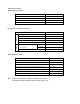
Bytes Machine Cycle A, #n 4 1 1 A←n4 Stack A XA, #n 8 2 2 XA ← n 8 Stack A HL, #n 8 2 2 HL ← n 8 Stack B A, @HL 1 1 A ← (HL) *1 @HL, A 1 1 (HL) ← A *1 A, mem 2 2 A ← (mem) *2 XA, mem 2 2 XA ← (mem) *2 mem, A 2 2 (mem) ← A *2 mem, XA 2 2 (mem) ← XA *2 A, @HL 1 1 A ↔ (HL) *1 A, mem 2 2 A ↔ (mem) *2 XA, mem 2 2 XA ↔ (mem) *2 A, reg1 1 1 A ↔ reg1 XA, @PCXA 1 3 XA ← (PC10 – 8 + XA) A, #n 4 1 1+S A←A+n4 A, @HL 1 1+S A ← A + (HL) *1 ADD
CHAPTER 9. INSTRUCTION SET Note Bytes Machine Cycle mem. bit 2 2 (mem. bit) ← 1 *2 f mem. bit 2 2 (f mem.bit) ← 1 *3 mem. bit 2 2 (mem. bit) ← 0 *2 f mem. bit 2 2 (f mem. bit) ← 0 *3 mem. bit 2 2+S Skip if (mem. bit) = 1 *2 (mem. bit) = 1 f mem. bit 2 2+S Skip if (f mem. bit) = 1 *3 (f mem. bit) = 1 mem. bit 2 2+S Skip if (mem. bit) = 0 *2 (mem. bit) = 0 f mem. bit 2 2+S Skip if (f mem. bit) = 0 *3 (f mem. bit) = 0 SKTCLR f mem. bit 2 2+S Skip if (f mem.
CHAPTER 9. INSTRUCTION SET CPU control Note 2 instructions Note 1 Mnemonic Note Operand Bytes Machine Cycle Operation IN A, PORTn 2 2 A ← PORTn (n = 0 – 3, 5, 6) OUT PORTn, A 2 2 PORTn ← A (n + 2, 3, 5, 6) HALT 2 2 Set HALT Mode (PCC.2 ← 1) STOP 2 2 Set STOP Mode (PCC.3 ← 1) NOP 1 1 No Operation Addressing Area Skip Condition 1. Instruction Group 2.
CHAPTER 9. INSTRUCTION SET 9.
CHAPTER 9.
CHAPTER 9. INSTRUCTION SET Operation Code Note 1 Mnemonic Operand B1 B2 mem. bit 1 0 B1 B0 0 1 0 1 f mem. bit 1 0 0 1 1 1 0 1 mem. bit 1 0 B1 B0 0 1 0 0 f mem. bit 1 0 0 1 1 1 0 0 mem. bit 1 0 B1 B0 0 1 1 1 f mem. bit 1 0 1 1 1 1 1 1 mem. bit 1 0 B1 B0 0 1 1 0 f mem. bit 1 0 1 1 1 1 1 0 bit-addr SKTCLR f mem. bit 1 0 0 1 1 1 1 1 bit-addr AND 1 CY, f mem. bit 1 0 1 0 1 1 0 0 bit-addr OR 1 CY, f mem.
CHAPTER 9. INSTRUCTION SET 9.4 9.4.1 INSTRUCTION FUNCTIONS AND APPLICATION Move Instructions MOV A, #n4 Function: A ← n4; n4 = I3 to I0 : 0 to FH Moves 4-bit immediate data n4 to the A register (4-bit accumulator). This instruction has a stacking effect (group A). When placed after a MOV A, #n4 or MOV XA, #n8 instruction, stack instructions following the executed instruction are processed as NOP. Application examples: ➀ Set 0BH into accumulator.
CHAPTER 9. INSTRUCTION SET MOV @HL, A Function: (HL) ← A Moves the contents of the A register to the data memory addressed by the contents of register pair HL. MOV A, mem Function: A ← (mem); mem = D7 to D0 : 00H to 3FH Moves the data memory contents addressed by 8-bit immediate data mem to the A register.
CHAPTER 9. INSTRUCTION SET XCH A, @HL Function: A ← (HL) Exchanges the contents of the A register and the contents of the data memory addressed by the contents of register pair HL. Application example: Exchange the data of data memory addresses 20H to 2FH and the data of addresses 30H to 3FH.
CHAPTER 9. INSTRUCTION SET 9.4.2 Table Reference Instructions MOVT XA, @PCXA Function: XA ← ROM (PC10 to PC8 + XA) Moves the high-order three bits (PC10 to PC8 ) of the program counter (PC) and the low-order four bits of the table data in the program memory addressed by the contents of register pair XA to the A register and the high-order four bits to the X register.
CHAPTER 9. INSTRUCTION SET 9.4.3 Arithmetic and Logic Instructions ADDS A, #n4 Function: A ← A + n4; Skip if carry; n4 = I3 to I0 : 0 to FH Binary adds 4-bit immediate data n4 to the contents of the A register and skips the next instruction if a carry is generated. The carry flag is not affected. When combined with an ADDC A, @HL instruction, this instruction becomes a base correction instruction. (See section 9.1.
CHAPTER 9. INSTRUCTION SET OR A, @HL Function: A ← A ∨ (HL) ORs the contents of the A register and the data memory contents addressed by register pair HL and sets the result into the A register. XOR A, @HL Function: A ← A ∨ (HL) Exclusive-ORs the contents of the A register and the data memory contents addressed by register pair HL and sets the result into the A register.
CHAPTER 9. INSTRUCTION SET 9.4.4 Accumulator Operation Instructions RORC A Function: CY ← A0 An to A1 ← An , A3 ← CY (n = 1 to 3) Rotates the contents of the A register (4-bit accumulator), including the carry flag, to the right one bit at a time. A Before Execution CY 3 2 1 0 0 0 1 0 1 1 0 0 1 0 RORC A After Execution NOT A Function: A ← A Takes the one’s complement (inverts each bit) of the A register (4-bit accumulator).
CHAPTER 9. INSTRUCTION SET 9.4.5 Increment/Decrement Instructions INCS reg Function: reg ← reg + 1; Skip if reg = 0 Increments the contents of register reg (X, A, H, L). When the contents of register reg become 0 as the result of incrementing, skips the next instruction. INCS mem Functions: (mem) ← (mem) + 1; Skip if (mem) = 0, mem = D7 to D0 : 00H to FFH Increments the data memory contents addressed by 8-bit immediate data mem.
CHAPTER 9. INSTRUCTION SET 9.4.6 Compare Instructions SKE reg, #n4 Function: Skip if reg = n4; n4 = I3 to I0 : 0 to FH If the contents of register reg (X, A, H, L) equal 4-bit immediate data n4, skips the next instruction. SKE A, @HL Function: Skip if A = (HL) If the contents of the A register and the data memory contents addressed by register pair HL, skips the next instruction.
CHAPTER 9. INSTRUCTION SET 9.4.7 Carry Flag Operation Instructions SET1 CY Function: CY ← 1 Sets the carry flag. CLR1 CY Function: CY ← 0 Clears the carry flag. SKT CY Function: Skip if CY = 1 When the carry flag is 1, skips the next instruction. NOT1 CY Function: CY ← CY Inverts the carry flag. If the carry flag is 0, it becomes 1 and if it is 1, it becomes 0.
CHAPTER 9. INSTRUCTION SET 9.4.8 Bit Manipuration Instructions SET1 mem. bit Function: (mem. bit) ← 1; mem = D7 to D0 : 00H to 3FH, bit = B 1 to B0 : 0 to 3 Sets the bit specified by 2-bit immediate data bit of the address specified by 8-bit immediate data mem. SET1 fmem. bit Function: (bit specified by operand) ← 1 Sets the data memory bit specified by bit manipulation addressing (fmem. bit). CLR1 mem. bit Function: (mem.
CHAPTER 9. INSTRUCTION SET SKF mem. bit Function: Skit if (mem. bit) = 0; mem = D7 to D0 : 00H to 3FH, bit = B1 to B0 : 0 to 3 If the bit specified by 2-bit immediate data bit of the address specified by 8-bit immediate data mem is 0, skips the next instruction. SKF fmem. bit Function: Skip if (bit specified by operand) = 0 If the contents of the data memory bit specified by bit manipulation addressing (fmem. bit) is 0, skips the next instruction. SKTCLR fmem.
CHAPTER 9. INSTRUCTION SET 9.4.9 Branch Instructions BR addr Function: PC10 to PC0 ← addr; addr = 000H to 77FH Branches to the address addressed by 11-bit immediate data addr. This instruction is an assembler pseudo instruction. During assembly, the assembler automatically replaces this instruction with the optimum instruction from among the BRCB !caddr and BR $addr instructions.
CHAPTER 9. INSTRUCTION SET 9.4.10 Subroutine Stack Control Instructions CALLF !faddr Function: (SP-1) ← PC7 to PC4 , (SP-2) ← PC3 to PC 0 , (SP-3) ← 0, 0, 0, 0 (SP-4) ← 0, PC10 to PC8 , SP ← SP-4, PC ← A10 to A0 faddr = A10 to A0 : 000H to 77FH Saves the contents of the program counter (PC; return address) to the data memory (stack) addressed by the stack pointer (SP) and decrements the SP, then branches to the address addressed by 11-bit immediate data faddr.
CHAPTER 9. INSTRUCTION SET PUSH rp Function: (SP-1) ← rpH, (SP-2) ← rpL, SP ← SP-2 Saves the contents of register pair rp (XA, HL) to the data memory (stack) addressed by the stack pointer (SP), then decrements the SP. The high-order side (rpH: X, H) of the register pair is saved to the stack addressed by (SP-1) and the loworder side (rpL: A, L) is saved to the stack addressed by (SP-2).
CHAPTER 9. INSTRUCTION SET 9.4.11 Interrupt Control Instructions EI Function: IME ← 1 Sets the interrupt master enable flag (1), and enables interrupts. Whether or not interrupts are accepted is determined by each interrupt enable flag. EI IEXXX Function: IE××× ← 1; ××× = N2 to N0 Sets the interrupt enable flag (IE×××) (1), and enables the interrupt.
CHAPTER 9. INSTRUCTION SET 9.4.12 Input/Output Instructions IN A, PORTn Function: A ← PORTn; n = N3 to N0 : 0 to 3, 5, 6 Transfers the contents of the port specified by PORTn (n = 0 to 3, 5, 6) to the A register. Note Only 0 to 3, 5 or 6 can be specified at n. Output latch data (output mode) or pin data (input mode) is fetched according to input/output mode specification.
CHAPTER 9. INSTRUCTION SET 9.4.13 CPU Control Instructions HALT Function: PCC. 2 ← 1 Sets the HALT mode (This instruction sets bit 2 of the processor clock control register.). Note The instruction following the HALT instruction is made an NOP instruction. STOP Function: PCC. 3 ← 1 Sets the STOP mode (This instruction sets bit 3 of the processor clock control register). Note The instruction following the STOP instruction is made an NOP instruction.
APPENDIX A. TABLE OF INSTRUCTION USABLE WITH EVAKIT-75X ONLY APPENDIX A. TABLE OF INSTRUCTION USABLE WITH EVAKIT-75X ONLY Since EVAKIT-75X (75X series common evaluation board) supports the 75X series functions, it can execute the following instructions not available with the µPD75402A. Since the µPD75402A and µPD75P402 cannot execute these instructions even though they can be executed on the EVAKIT, do not use them.
APPENDIX A. TABLE OF INSTRUCTION USABLE WITH EVAKIT-75X ONLY Mnemonic DECS SKE Mnemonic Operands mem NOT1 Operands fmem. bit @HL pmem. @L A, reg @H + mem. bit XA, rp’ BR !addr XA, @HL PCDE @HL, #n4 PCXA A, mem BCDE pmem. @L BCXA SET1, CLR1, SKF, SKT, SKTCLR @H + mem. bit CALL !addr AND1, OR1 CY, pmem. @L PUSH BS CY, @H + mem. bit POP BS CY,/fmem. bit IN XA, PORTn CY,/pmem. @L OUT PORTn, XA CY,/@H + mem. bit SEL MBn XOR1 CY, @H + mem.
APPENDIX B. DEVELOPMENT TOOLS ★ APPENDIX B. DEVELOPMENT TOOLS The following development tools are available for system development using the µPD75402A: Language Processor RA75X relocatable assembler Host Machine OS PC-9800 series MS-DOSTM Supply Medium Ordering Code (Product Name) 3.5-inch 2HD µS5A13RA75X 5-inch 2HD µS5A10RA75X 5-inch 2HC µS7B10RA75X ~ Ver. 3.30 Ver. 5.00 A* IBM PC/ATTM PC DOSTM (Ver. 3.
APPENDIX B. DEVELOPMENT TOOLS Debugging Tools The following in-circuit emulators (IE-75000-R and IE-75001-R) are available as the µPD75402A program debugging tools. Their respective system configurations are as follows. IE-75000-R*1 Hardware IE-75000-R-EM The IE-75000-R is an in-circuit emulator for hardware/software debugging in development of an application system using the 75X series. Used in combination with an emulation probe.
Development Tool Configuration In-Circuit Emulator Emulation Probe IE-75000-R IE-75001-R IE-75000-R-EM IE Control Program Host Machine PC-9800 Series IBM PC/AT (Symbolic Debugging Capability) *1 EP-75402C-R EP-75402GB-R RS-232-C *2 PG-1500 Controller On-chip PROM Products PROM Programmer µ PD75P402C/CT/GB PG-1500 Relocatable Assembler Programmer Adapter PA-75P402CT PA-75P402GB * 1. The IE-75001-R does not incorporate the IE-75000-R-EM (Sold separately) 2. EV-9200G-44 Target System APPENDIX B.
APPENDIX C. MASK ROM ORDERING PROCEDURE APPENDIX C. MASK ROM ORDERING PROCEDURE When completing the µPD75402A program and ordering the mask ROM, proceed as follows: ➀ Mask ROM order reservation Provide us with the mask ROM ordering schedule through your dealer or our sales department (If we are not informed in advance, processing may be delayed.). ➁ Preparation of ordering medium The medium for mask ROM order is UV-EPROM or 8-inch IBM format floppy disk.
APPENDIX D. INSTRUCTION INDEX (ALPHABETIC ORDER) APPENDIX D. INSTRUCTION INDEX (ALPHABETIC ORDER) Instruction Page Instruction Page ADDC A, @HL 163 NOP ADDS A, #n4 163 NOT A 165 ADDS A, @HL 163 NOT1 CY 168 AND A, @HL 163 OR A, @HL 164 AND1 CY, fmem. bit 170 OR1 CY, fmem. bit 170 BR addr 171 OUT PORTn, A 175 BR $addr 171 POP rp 173 BRCB ! caddr 171 PUSH rp 173 CALLF ! faddr 172 RET 172 CLR1 CY 168 RETI 172 CLR1 fmem.
APPENDIX E. HARDWARE INDEX (ALPHABETIC ORDER) APPENDIX E.